What wiring techniques and gadgets (clamps etc) can I use on the underside of the bench top to keep everything looking neat, simple, and organized. I'm going to use Mianne benchwork for my 22'x9.5' layout.


|
|
What wiring techniques and gadgets (clamps etc) can I use on the underside of the bench top to keep everything looking neat, simple, and organized. I'm going to use Mianne benchwork for my 22'x9.5' layout.
Replies sorted oldest to newest
Choose a color code and stick to it.
Yes, stick to your guns. Every time I started a new layout, I was going to keep the wiring neat. Now for my second joke.....![]()
MichRR714 posted:Choose a color code and stick to it.
True story. A fellow model railroader, who lived up the street from me, was having electrical problems on his layout. My career choice and a dad who was electrically inept ( no offense intended dad) made me pretty good at trouble shooting. My friend was very good at scenery, I mean really good, almost an artist but electrical skills were quit lacking. He had two switches he wanted to throw at the same time. No big deal, common stuff. When I inspected his wiring, he had used the same color, red in this case, for everything. He ran out of red and switched to black. I did get the switches to work but the wire tracing took some time. So, yeah, choose a color code and stick to it.
DP posted:Yes, stick to your guns. Every time I started a new layout, I was going to keep the wiring neat. Now for my second joke.....
I feel you, bro! ![]()
Pete
Charlie wrote: "Choose a color code and stick to it." Also write it down! Make multiple copies of it and mount it, tape it, or staple it under your benchwork for easy reference.
I drilled holes in my benchwork and used conduit clamps.


Colors, colors, colors----use colors[and white, in my case for Common]

I too use the Mianne. Not wishing to drill holes through the beams, I use the following functional, if not beautiful, technique. Get some of the straight lengths of tie wire used for suspended ceilings, the steel 12 gauge stuff not the 18 gauge they use in residential. You can also get the 12 gauge in rolls, but it is a pain to straighten, the straight lengths are much easier if you can get them. Then, I tie lengths of this wire to the bottom of the Mianne beams, using small ties wraps through unused dowel holes. Yes, the tie wraps will be angled. You may not always have a convenient dowel hole, improvise! Then, I hang lazy loops made out of tie wraps over the steel wires, and you now have wire hangers that may be moved or adjusted as necessary. If the wiring ever becomes 'Final" or "Permanent" you can tighten the tie wraps, but I have never had a layout get to that point.....
Planning is a big part of any solution. I will also agree with the comments regarding color coding, or at least labeling!
There my be a lot of colors of wire available, but I stick to 10, because that is the number of digits we use. In electronics, resistors are marked with colored bands, 0 - 9. This is known as "color, symbol for number".
If you need further numbering, electrical tape is available in all 10 colors.
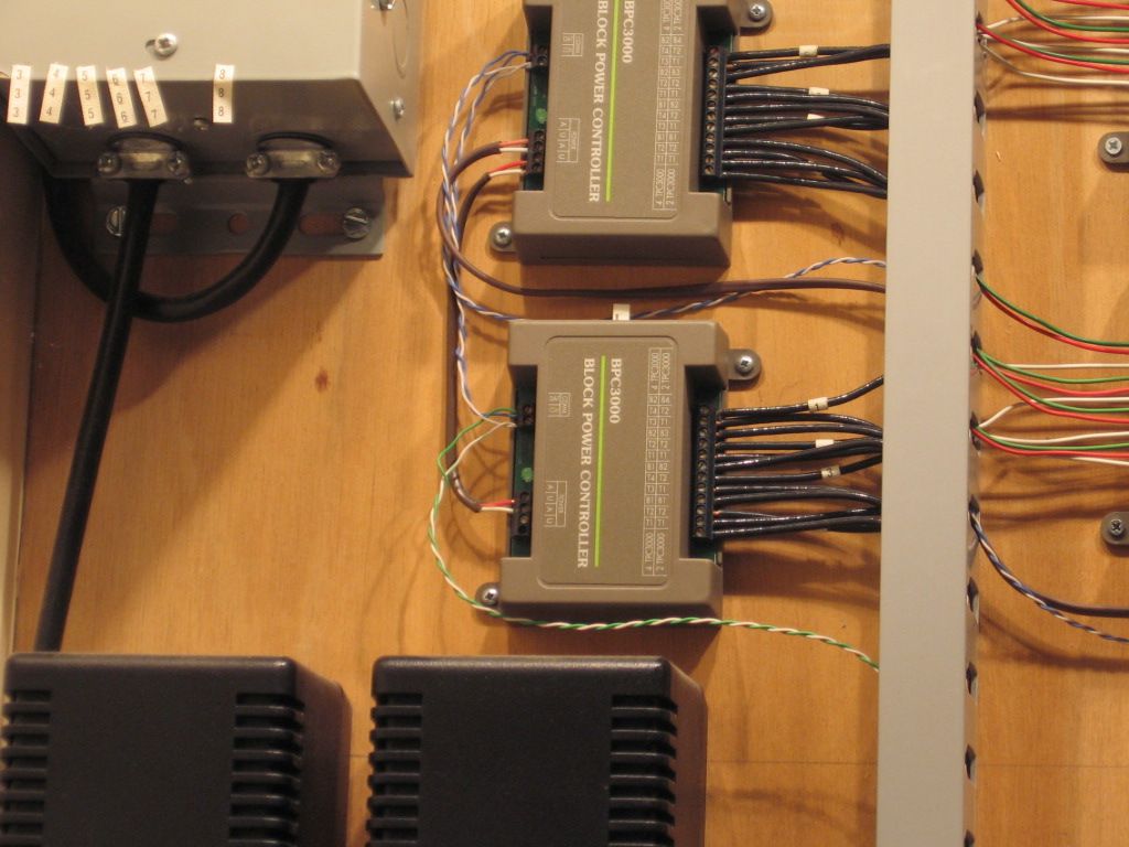
This relay panel was wired using the numeric color code. There are 20 relays per row.

The colors make it easy to find the number I'm looking for. I also have a printed sheet with all the information.

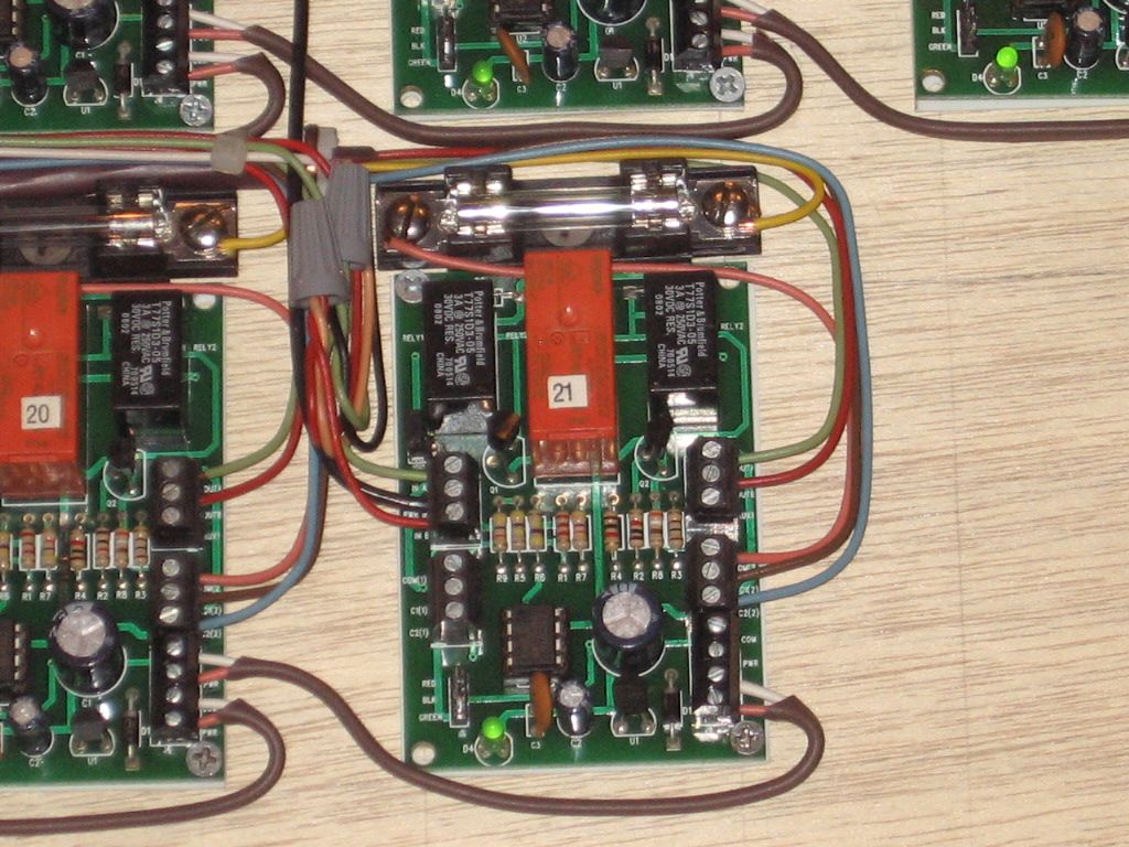
Here I'm in the process of reorganizing one of my power supplies. Between the colors and the direction the wires are coming from, made it fairly easy to identify each one.

This is one style of wire hanger that I use.

These are nice because you can open and close them. They are designed for pulling wires, but can be left in place. I picked these up years ago at a surplus store.

This is my method of choice though, a nylon strap screwed to the benchwork, with a simple tie wrap to hold the wire. This method is great for pulling, and when you're done, just cinch the tie wrap down. Nice neat bundle. I don't drill holes in my benchwork for wiring.

I drilled holes in my Mianne cross braces and installed plastic bushings with a little RTV to hold them in place. The Mianne cross braces are too thick for the bushings to grab with their intended fastening barbs. For running the wire I used the gray two hole plastic conduit straps as shown above by C&O ALLIE. Fastened them to the underside of the table top using only one screw in one hole (a good tip posted here by another forum member). This way you can easily pull them down to add additional wires. Color coded wiring is also highly recommended as is the documenting of the colors used and placing reference lists around everywhere so they are easy to refer to later on. I used OGR wire for all my power, but it is marked with colored electrical tape for each power block. However, I didn't do so good with the reference lists and now have to go back and document which color went where. Never thought I would forget so quickly...
A Photobucket slideshow. Click on the link.

What your Relays used for Signals, if so could we see your Signal on your Layout ?
Anyway. Very nice.
Thanks, john


 Not as good as some, but here's what I do. The wire channel works great for the switches.
The Atlas 6924 relay boards control/enhance the operation of, 25 switches.
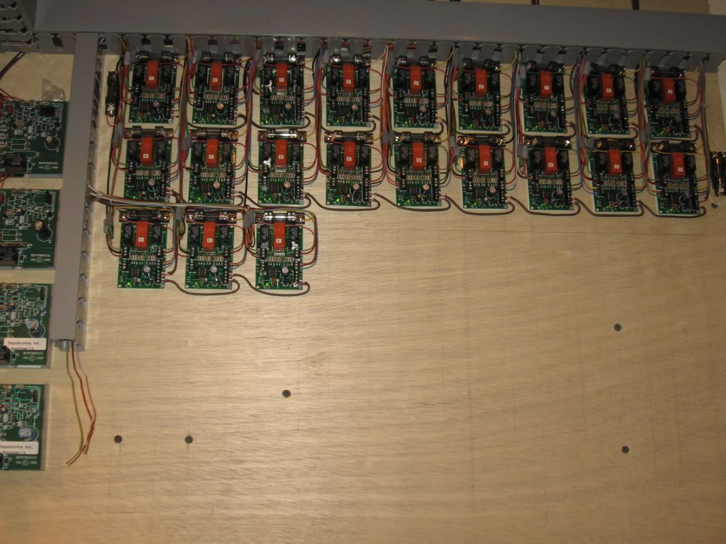
The other boards control crossing gates.

(5) of the (6) boards to the right pictured are TMCC control of switches. Lower right board is programmed for accessories. Two boards to the bottom left are Block Power controllers, (8) track circuits.
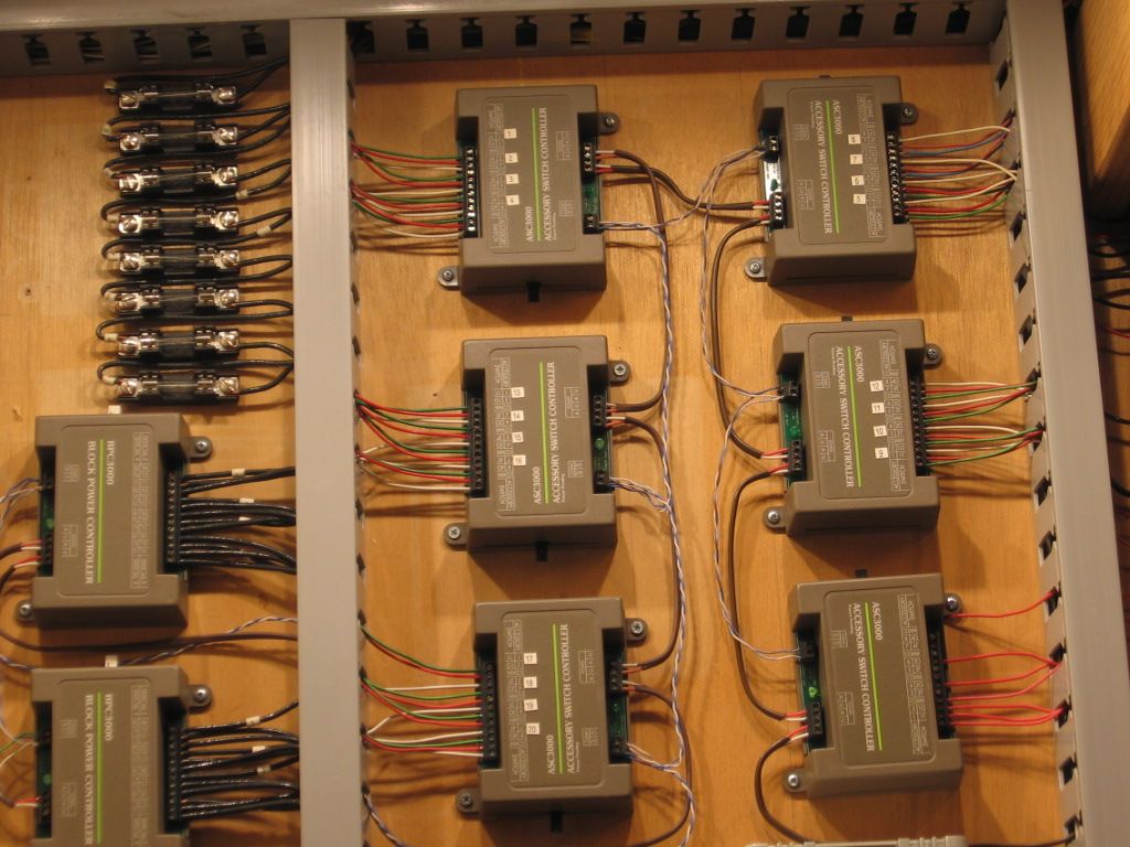
Block Power controllers.
There is pictured a Lionel SC-2 that controls one switch.
I would be happy to help you layout your wiring plan and components to use. Visit my website www.montanarailpower.com you can contact me if you are interested.

")
")
Geesh,Steve, you even have your boxes organized!![]()
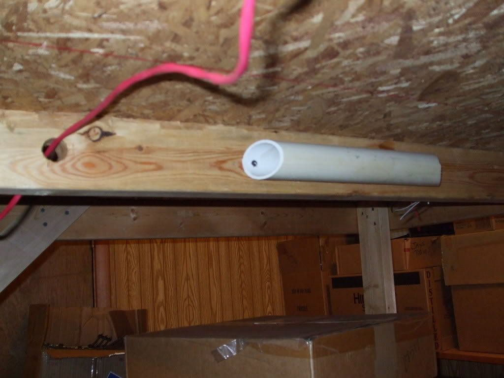
On my old tables, I drilled a 1" hole through each joist about a six inches in from each end. In between them, I took a piece of 1 1/2" PVC scrap and screwed it into the joist. When I cut the pipe, I beveled the edges to make it easier to screw them down (picture a trapezoid made of pipe). I put these on every joist, but only on one side so I had plenty of room on the other side to mount terminal blocks or circuit boards.
As for the wiring itself, I had access to a bunch of near empty spools of fire alarm cable. Most of this cable is 2 conductor 14 AWG in a fire resistant jacket. I use a color code to identify if the cable is for track power or accessory power or lighting, by using electrical tape to make a "flag" on each end of the cable. I also write down (with a Sharpie) what the cable is for. For example "140 Banjo Signal Post C" which would mean the cable powers up a banjo signal from Post C on the ZW.
Well, I don't use the ZW anymore, so I have TPC 300s that are labeled post A or D and a Powermaster that is labeled post C. A Malibu Lighting transformer is labeled post B and is for lighting. All the associated terminal strips are also labeled with a colored piece of electrical tape (hindsight being 20/20, I should have painted them before installing them)
On the new table, which is only 4' x 4', I just used plumbers straps and screwed them to the sides of the joists. They hang down so there is about a 1/4" gap between the short side of the J and the bottom of the joist, so I can slide wire through that gap instead of having to pull it through each strap as I go. I can't seem to find a picture of this so hopefully I explained it adequately.
J White
Very nice. Please don't forget Integrated Signal Systems.com
They have very nice, Rail Road Signals and NYC type Subway Transit Signals too.
Very nice Relays set up.
Thanks, John
Tom Tee posted:Elliot, Mike what is your opinion of European terminal strips. I notice like me, you both use conventional t/s.
Tom Tee posted:There are 12 standard colors and many more on special order that will make change or service jobs much easier down the road.
Tom, if that's your benchwork fastened to the concrete block wall, I would grade it an A+.
Access to this requires an OGR Forum Supporting Membership