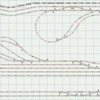
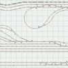
I attached a rrt. file for those who can open the track plan. Thanks to RTR12 I was able to edit by also attaching a picture of the layout. It is a fastrack around room layout. I have one Z4000 and one Z1000 for power supply (both MTH). If possible I want to use only the Z4000. I have two TIU's. One is the latest with the better signal. I will use that one. Also have two MTH 12 terminal blocks, 200 ft. of 16 gauge wire, and two toggle switches for cutting blocked power on yard tracks (will purchase more). My concerns are where to place the TIU, terminal blocks, power districts/blocks, and wire routing (especially across the walk through access on lower left section of straight double mainline track). I will be placing two lift out bridges (the new Lionel bridge #6-82110) in that open access. It is a basement layout. So there are 2 supporting poles in the basement. One is between the reverse loops, the other is on the lower right between the 2 main lines and the yard station/yard entrance at lower reverse loop entrance. I do need to purchase a volt meter.

I will have a roll out "operations" table from under the benchwork at the bottom of the plan to the right of the open access. I tried to scan the printed plan to my PC. so I can attach it to this message, but it's not working for me. Again your help is appreciated.  

                                                                                 Thanks, Fred in New Hope, PA


Attachments

Last edited by luvtrains
Original Post

Replies sorted oldest to newest

From RRT, you can export a .bmp file from the File Menu > Export > Windows BMP. This can be posted here as is. Or using something like the free Irfan View program you can easily load your bmp file and 'Save As' a jpg.


I probably won't be much help with the layout wiring, but will take a look. I do like studying the track plans of others in hope of improving my own someday.


I did an export of your rrt file and converted to jpg and attached it here.


Attachments

Images (1)
  • Fred's Layout Final 7.9.15 rev 2
Last edited by rtr12

You are welcome.


Since you have no suggestions on wiring...and you probably know more about this than I do (I am still pretty green about all this, still learning myself), but here goes. For track power, I used the MTH terminal blocks. I have grown to like them. I think on your track plan I would go from your cart location to the far right and then up and down the far right section and back around each top and bottom section to the lift out. Trying to follow Barry's book's as closely as possible.


Make blocks the recommended lengths (10-12 track joints, I think it was), isolate the loops and sidings. I would install switches on the sidings so I could park trains and not run up the run time clock. Make sure you get at least a 10 amp rated switch for switching your track power to the sidings. Your plan is a bit more complex than mine and I am not really sure what to suggest for TIU channel use? I am thinking probably 3 channels?


Of course you want to use a separate power source for your switch machines and accessories, other than track power. I was going to use an AIU, but to get going I just installed the switch buttons near the switches. I ended up liking it that way and may just leave them that way. Although adding an AIU and the use of routes is something that still sounds interesting to me, so I may add AIUs in the future.


Can't think of anything else just now, but I am sure I probably missed a lot of things.


Just as an FYI, I currently have a 6'x16' table with two isolated loops with one fixed TIU channel per loop. Each TIU channel is powered by a Lionel PH-180 and the TIU is powered with a Z500 from a starter set. Each loop has four isolated blocks (center rail) with a power feed pretty close to the center of each block. I tried to follow the book as best as I could, but cheated a little with the locations of the MTH terminal strips, they are not equally spaced nor are the track feeds from the terminal blocks. My layout is not that large, but I have had absolutely no problems on it with either DCS or Legacy. Everything works very well, which sold me on the MTH terminal blocks and the book's wiring recommendations.


Good Luck, and maybe this will get some more discussion going to correct all my errors.  

Hi Fred,

You have the layout nicely refined with everything fitting.


First some logic, before physical planning. Take these as an approach to consider.


Running command, first separate the outside runs from the inside runs using fixed 1 and fixed 2.Separate them by pulling the jumper from the 1 3/8" at the crossovers between the switch turnouts.


For blocks, find the 1 3/8" pieces around the runs and make blocks in between those. Same concept. You can easily remove the center rail jumper wires to create the isolation points.


In order to see this visually, color code the Fixed 1 and Fixed 2 loops, then use something like red to indicate the locations of the 1 3/8". That will physically show you blocks.


A quick look shows that would work out nicely, with perhaps one or two blocks only a few tracks too long.


The yard spurs need to have a 1 3/8" inserted just after the switch or use the fitter piece with the 060 & 072 switches. Pull the center jumper wire and use a toggle or AIU port to control the power.


Then, you'll know where to place the terminal blocks for efficient use of the wire.


Where do you plan to locate the power and control center?


Last edited by Moonman

RTR thank you for the advice. I also like the MTH blocks. I did not know about the 10 amp rated switches for switching power. I have to check the ones I already have. I don't plan to use an AIU as of now. (no automated accessories). The fastrack turnouts will run off track power. The newer ones  I purchase will probably have the command control option if I choose to go that route. I was also thinking 3 channels, but if I can get it down to 2 channels that would be better. Have to tread carefully on that one. Your help is greatly appreciated. Thanks, Fred

Carl, thank you! I do prefer to use 2 fixed loops rather than 3. I will see how that goes. Your color coded version will help greatly. My MTH terminal blocks have a max of 12 connections. I have 2 of them. If I have to use another terminal block I can use my older TIU (magic bulb) for a 3rd fixed section which will be the station/yard area/lower reverse loop. I would use the fitters of 060 or 072 turnout entering that lower loop for blocks for that section.

This plan helps me visualize where to place terminal blocks. The TIU or TiU's will be placed at, or slightly above track level between the upper reverse and lower reverse loops (a bit to the right and closer to the lower loop. As of now I have:

        Block "A" with 12 connections / blocks for the outer main and elevation/grade section....each to be labelled A1 thru A12

        Block "B" with 10 connections/blocks for the inner main and upper reverse                   loop.....labelled B1 thru B10

        Block "C" with 11 connections/blocks for lead (off of upper loop) to station yard           area (lower reverse loop). From that reverse loop I would use the last turnout             (at left side) which exits/enters reverse loop to inner main...labelled C1 thru C11.

My concern is at the 2 crossovers from inner to outer mains. I will use the fitters for blocking between connected turnouts....if I should have a passenger or freight train leave inner main ot outer, and immediately use the next attached turnout right back to the inner main would that move cause electrical problems...short, unstable amp/volt readings? I know I need to "phase" if I decide to also use the Z1000 transformer.

I will be rereading the DCS companion this p.m. or tomorrow a.m. . 

Last edited by luvtrains

Carl I also have a Z4000. I plan to use that for blocks A and B. The Z1000 for block C...the lower reverse loop/station/yard area. If I can figure it out per your advice, I wish to use only the Z4000 with one TIU (latest version). Otherwise, I have the other option available. The simpler, the better is for me. By the way, thank you for the complement on my refining the layout.

Originally Posted by luvtrains:

RTR thank you for the advice. I also like the MTH blocks. I did not know about the 10 amp rated switches for switching power. I have to check the ones I already have. I don't plan to use an AIU as of now. (no automated accessories). The fastrack turnouts will run off track power. The newer ones  I purchase will probably have the command control option if I choose to go that route. I was also thinking 3 channels, but if I can get it down to 2 channels that would be better. Have to tread carefully on that one. Your help is greatly appreciated. Thanks, Fred

You are welcome. The 10 amp (or more, more is better) switches should assure you never have problems no matter what power you use for your track or how much power your trains draw. The TIU channels are 10 amp rated and I think that is also the largest available output for a single power supply.


Two channels would probably be fine. One for your outer loop and one for your inner loop, yard tracks and reverse loops. Although my layout is smaller, I have 4 spurs and 2 on my inner loop and it's set up with two channels, one outer and one inner.


I don't have a Z4000, but aren't they 10 amps per handle or close to it? I think you would be ok with one handle per TIU channel (and loop of track). You could switch off the parked trains when not in use. The trains I have, all command control, only use about an amp per engine with smoke on, so I never get close to my PH-180s 10 amp capacity. I don't have any passenger cars, but I do have a lighted caboose or two, searchlight car and some things like that.

Luvtrains,

one of the things that might really help you is to use 5 different wire colors.

example

Outer loop center rail Blue

inner loop center rail Orange

accessory power yellow

Yard/switch power red

Or some variation depending on a number of things.

ground white


You should use no less than 8 barrier strips on that layout(maybe more). 


in your case the wiring off the barrier strips would go to the TIU and other components would differ but the basic idea is there.


hope this helps.

Last edited by aubv

I concur with rtr12. The Z4000 and 1 TIU (2 channels) will be fine. The Z1000 is only a 100watts. The brick is perfect for accessory power as it has the 14v fixed output.


The yard will run fine connected to the blue or B loop.


Do you know how to turn off the elevations being displayed on the track joints? That's why I didn't block that run.


I worked on the block a little more. if you use a 5" + a 5" Block in place of a 10" at around 4.25" you'll get 10 blocks for loop A. There are 10 for loop B.


That's leaves 2 pair of terminals on each distribution board for add-ons if needed.

Attachments

Originally Posted by aubv:

Luvtrains,

one of the things that might really help you is to use 5 different wire colors.

example

Outer loop center rail Blue

inner loop center rail Orange

accessory power yellow

Yard/switch power red

Or some variation depending on a number of things.

ground white


You should use no less than 8 barrier strips on that layout(maybe more). 


in your case the wiring off the barrier strips would go to the TIU and other components would differ but the basic idea is there.

 hope this helps.

aubv,

he has two MTH 12 port terminal boards.50-1014  One feed hot and common in, 12 pair out.


Color coding is always good.

Originally Posted by Moonman:
Originally Posted by aubv:

Luvtrains,

one of the things that might really help you is to use 5 different wire colors.

example

Outer loop center rail Blue

inner loop center rail Orange

accessory power yellow

Yard/switch power red

Or some variation depending on a number of things.

ground white


You should use no less than 8 barrier strips on that layout(maybe more). 


in your case the wiring off the barrier strips would go to the TIU and other components would differ but the basic idea is there.

 hope this helps.

aubv,

he has two MTH 12 port terminal boards.50-1014  One feed hot and common in, 12 pair out.


Color coding is always good.

Moonman,

Undestood, however wiring the layout doesn't stop at powering the track. In my opinion, there are better options than the MTH terminal boards.

Originally Posted by aubv:
Originally Posted by Moonman:
Originally Posted by aubv:

Luvtrains,

one of the things that might really help you is to use 5 different wire colors.

example

Outer loop center rail Blue

inner loop center rail Orange

accessory power yellow

Yard/switch power red

Or some variation depending on a number of things.

ground white


You should use no less than 8 barrier strips on that layout(maybe more). 


in your case the wiring off the barrier strips would go to the TIU and other components would differ but the basic idea is there.

 hope this helps.

aubv,

he has two MTH 12 port terminal boards.50-1014  One feed hot and common in, 12 pair out.


Color coding is always good.

Moonman,

Undestood, however wiring the layout doesn't stop at powering the track. In my opinion, there are better options than the MTH terminal boards.

Agreed. Where one can use a bus type supply, such as accessories or TMCC/Legacy, the barrier strips work well.


However, when one needs a terminal bus, the MTH are handy and reliable. Some use ground bus bars from electric panels and I use these


Last edited by Moonman

aubv, Thank you for the information. I printed it to read more closely later. I do need advice for accessories. Just focusing on the track blocking as of now because when it comes to wiring I become overwhelmed. I can't begin to tell you what I have done to the wiring just to change a light fixture in a former co-op apartment years ago.

Originally Posted by luvtrains:

aubv, Thank you for the information. I printed it to read more closely later. I do need advice for accessories. Just focusing on the track blocking as of now because when it comes to wiring I become overwhelmed. I can't begin to tell you what I have done to the wiring just to change a light fixture in a former co-op apartment years ago.

Fred,

I sent you an e-mail.


Originally Posted by luvtrains:

Carl to set grades to zero, click on grades menu at top. Choose selection (elevated,or grade)  then choose "set at zero elevation. Thanks for the blocking display. that will help greatly!

I just wanted to make the grade numbers not visible to permit viewing the track joints.


I didn't want to mess with your grade settings.

Originally Posted by John H:

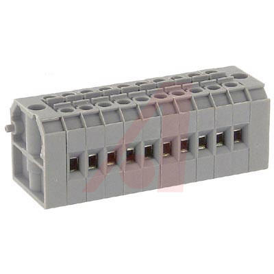
Back to the terminal bus, these are reasonable and less work.

Not sure why these are less work but they certainly aren't nearly as flexible. In addition, they maybe more expensive.


Originally Posted by rtr12:

I am with John H on the 'reasonable and less work' type terminal strips. From lessons learned during my working life, I am not a big fan of crimp connectors. They look nice, but can cause a lot of headaches, even when installed by professional trades people. Not to mention added costs.

There is no "need" to use solderless connectors. That said, the cost for a even a medium size layout, including the purchase of a ratcheting crimping tool and 3M connectors is less than $150 dollars. 

u

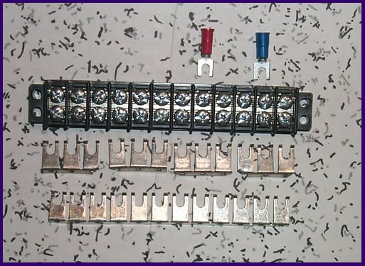
I have a double tracked Fastrack layout.  O84 outside and O72 inside.  there are two O72 Fastrack crossovers, and a storage yard with about ten turnouts.   fastrack is easy to wire, all you have to do is find the right size crimp on connectors.  I powered my track with a Z4000 and TIU.  One handle for the inside and one for the outside.  I also used a Z1000 to provide power to all the switches and accessories.  My layout is 15' X 28' with a 12' storage yard that has about 10 turnouts.  When I put power drops on my track I added one to about every forth section of track.  I have no power issues and get 10's all the way around my one scale mile loops.  I used a product from Allied electronics called a CMB4-10.  It's a terminal block that has space for 20 wires.  Just strip the wire and tighten the screws.  Contact me off line and I can send you the information on the products i used.

Originally Posted by aubv:
 
Originally Posted by rtr12:

I am with John H on the 'reasonable and less work' type terminal strips. From lessons learned during my working life, I am not a big fan of crimp connectors. They look nice, but can cause a lot of headaches, even when installed by professional trades people. Not to mention added costs.

There is no "need" to use solderless connectors. That said, the cost for a even a medium size layout, including the purchase of a ratcheting crimping tool and 3M connectors is less than $150 dollars. 


Some terminal strips do "need" crimp connectors for a good termination. All I am saying is I much prefer the terminal strips that have a means of clamping down on a bare, stripped wire end for a good and proper connection. That's $150 I could be spending on trains.

Thanks jmiller. It appears from what you and others have indicated I shouldn't worry about limiting the terminal to 12 or 15 wire connections....a little more won't hurt as long as I don't get carried away. What is a 10 pole jumper? Not famiiar with that term or its use. I am now determined to limit my power to 2 Z4000 handles. The simpler the better for me. Future working accessories might be 2 or 3 industrial ones. However with all the track space consuming the layout and few buildings I have there is not  much more room. I might put a partial platform above the track to have a city/town scene. That won't be for some months away. And yes I also find the fastrack easy to connect. I just have to make sure that I have connectors that fit for 16 gauge wire and the ground/ common connection on the fastrack.

On the bus bar I suggested, you don't have to use the wire. You can just use the first two terminals to feed the bar. Then the bus will handle any amps you wire it for. I like the type jmiller uses for the small wire I use to extend switch controllers. They pinch the wire; a set screw can cut that phone wire right off when tightened. I use 4 conductor phone wire for Fastrack switches-colors are the same.

Look at the photo above.  The CMB4-10 has ten slots to install your wire.  One in and one out for a total of 10 spaces.  The sell a jumper that goes in the center that connects all of the wire slots together which gives you 20 spaces to connect the wires.  19 from the track and one to your TIU or Power supply if you don't use a TIU.  Allied also sells the crimp on connectors.  I think they are .110 tab size.  You would need two of the terminal blocks.  One for your center wire and one for the outside ground.  The CMB4 is available in several sizes from one connector up to one hundred spaces. 
 
Originally Posted by luvtrains:

Thanks jmiller. It appears from what you and others have indicated I shouldn't worry about limiting the terminal to 12 or 15 wire connections....a little more won't hurt as long as I don't get carried away. What is a 10 pole jumper? Not famiiar with that term or its use. I am now determined to limit my power to 2 Z4000 handles. The simpler the better for me. Future working accessories might be 2 or 3 industrial ones. However with all the track space consuming the layout and few buildings I have there is not  much more room. I might put a partial platform above the track to have a city/town scene. That won't be for some months away. And yes I also find the fastrack easy to connect. I just have to make sure that I have connectors that fit for 16 gauge wire and the ground/ common connection on the fastrack.


Add Reply

Post
The DCS Forum is sponsored by

OGR Publishing, Inc., 1310 Eastside Centre Ct, Suite 6, Mountain Home, AR 72653
800-980-OGRR (6477)
www.ogaugerr.com

×
×
×
×
Link copied to your clipboard.
×
×