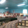
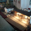
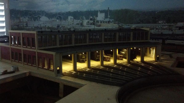
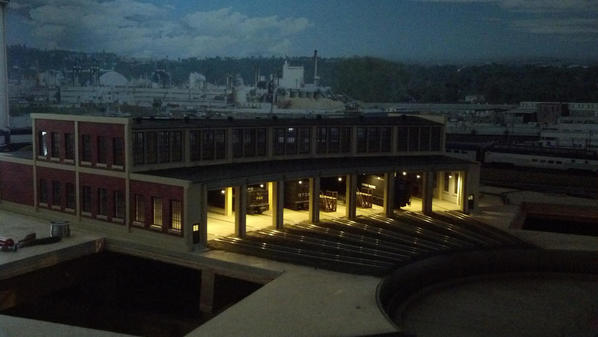
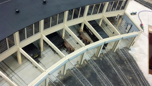
It's just about time to add the lighting to this monster. I think I'm going with LED's, 3mm, flat top, warm white style. I'm looking to do it similar to the way that the Korber website roundhouse instructions show. I'm not an electrical guru so I'd like some opinions or ideas to best do it. You see the pic below, I plan to mount the LEDS to a Plsatruct lamp shade and then mount that to the side of the roof beams in each of the stalls. I'm looking at about 36 leds on the roof beams, plus 4 additional LEDs for the 4 doors on the RH.


Can all of these be powered from one 12 volt supply?


Do you think I would be better using the LED strips and have a dimmer installed as well? 


I'm curious what you guys think for lighting this thing. Thanks in advance for your help.


IMG_01281

Attachments

Images (1)
  • IMG_01281
Last edited by Former Member
Original Post

Replies sorted oldest to newest

First off, yes, one supply will light all those LEDs and a lot more.


It would probably be easier to use the strips with a 12V supply.  Obviously, they won't be in neat little lampshades.


For individual LED's, I'd look for the wide angle ones to spread the light more, many LED's provide a semi-focused beam and would leave hotspots and dark areas inside.  For individual LED's you can wire three in series and then use a 150 ohm resistor in series with each string.  With 12 volts, that will give you pretty bright lighting.  If you have a variable supply, you'll have a pretty narrow range from full on to dark, about 9 volts off to 12 volts full on.  It's similar with the strips, as they have three individual LED's in series with a 150 ohm resistor.

Rich, thats what I mentioned in my original post. Thats where I got the idea of using flat top wide angle LEDs and Plastruct lamp shades. I really like that method a lot.

We have 12 volt wall warts and several post war ZWs we can use as a power source. I was going to use a ZW and some of the converts off Ebay that I have seen linked here on the forum. They would convert the ac to dc, and adjustable voltage. I can get or use anything I need to, once I have a set plan.

Sorry, I missed the intent was the installation.


You really don't need a ton of power for the led's, depending on the size of the wall wart it may work.  for dimming you can use some additional resistance, or a power divider/pot on the hot leg and dial in some resistance to adjust the actual amount of light.


The strips are simpler, but I think you would find that they put out too much light.


Good luck.


Originally Posted by Laidoffsick:
Rich, thats what I mentioned in my original post. Thats where I got the idea of using flat top wide angle LEDs and Plastruct lamp shades. I really like that method a lot.

We have 12 volt wall warts and several post war ZWs we can use as a power source. I was going to use a ZW and some of the converts off Ebay that I have seen linked here on the forum. They would convert the ac to dc, and adjustable voltage. I can get or use anything I need to, once I have a set plan.

Using the individual bulbs and the lampshades, I would say that driving the lights with one of those converter boards with a dimmer would be the best combo for your needs. Then you could supply power from any source. Also, the lights could be connected anyway that you like without using other components.


Nice roundhouse!


Thanks everyone, I appreciate the input. Stan & GRJ I have read many, many posts throughout the forum from you on LEDs. Stan I like the banks idea, and love the video of the hangar.


So this is what I am leaning towards...


Power from a Postwar ZW.... just because we have a few and why not use them for access power.


AC-DC converter to dim lights as well 


flat top wide angle LED


Lamp Shades


The only thing I'm unsure of at this point is hook up wire and resistors. I'm thinking 24-30ga wire, I assume that is sufficient. The resistors however, I have no clue. Those LEDs from Ebay say they come with free resistors but I don't know if they are what I should/can use, or do I need something different/better.

Last edited by Former Member

#30 wire is plenty, anything bigger is just a bonus.  I wire all my LED lighting upgrades in locomotives with #30 wire, easy to hide.


The series resistors for a bank of three are 150 ohms 1/4 watt.  These are really load balancing resistors in this case, as every string of three won't have exactly the same characteristics.  The resistors allow all of the LED's to run at the same intensity.

I just saw this thread.  Since my experience is written up in the Korber instructions, I should comment.  I used the 3mm flat-top LED's with Plastruct shades.  The appearance is very good.  I installed 5 LED's along the beams between stalls in the Korber 30" roundhouse.  They really don't put out enough light for my taste. 


I plan to keep them but supplement them with some segments of the LED strips that come on a reel.  These will be attached to styrene inverted U-shaped channels that will in turn be attached under the beams of the house.  The sides on the channels will be painted black and will keep the LED strips from being visible when looking through the side roundhouse windows.


If I was doing the job again, I'd install twice as many LED's with shades and the light output would then be adequate.

Thanks John, #30 it is.


Bob, thanks for chiming in, I was hoping you would. I have 6 roof beams, and the RH is almost 36" deep. So I was thinking 9 LEDs for each stall, giving me a total of 54 inside the RH. I'm hoping that will be enough. With banks of 3, I can put a set of 3 on each roof beam, and then make the separate banks for either each stall, or front, center, and rear portions of the RH. I think prototypically speaking, the banks would probably be per stall, so they could light each stall individually.


You can't really get close to the RH, based on it's location on the layout. It's so big, and about 50" off the floor, it's very easy to see, especially in through the stall doors.


IMG_1288

IMG_1290

Attachments

Images (2)
  • IMG_1288
  • IMG_1290
Originally Posted by Bob:
If I was doing the job again, I'd install twice as many LED's with shades and the light output would then be adequate.

This is one of those you have to see it for yourself to appreciate the wisdom of this comment.  Whether it be from adding more fixtures or using brighter LED's, this has been my experience when lighting up a wide variety are structures if you want the viewer to see interior detail.  Not all 3mm LEDs are created equal and I sometimes wonder about the claimed intensity (millicandela or mcd) specs on eBay listings.  Bottom line is you need to experiment a bit to insure you have enough brightness. 


I think you want to be able to look through the doors and windows and see detail:
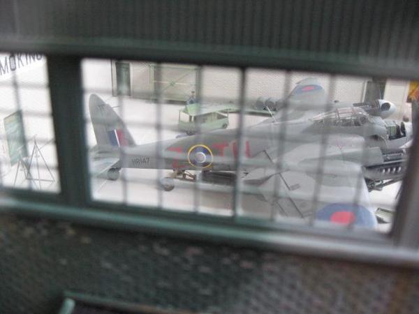
 

ogr rh relative lighting

For whatever reason I've found you need MORE interior brightness than you'd think when shooting photos/videos than when seeing it in person. So take test photos like above so the rest of us can appreciate your handiwork!


If you haven't messed with these voltage converter modules, something that's not obvious is the screwdriver adjustment is multi-turn and it can take several turns using a tiny jeweler's type screwdriver to change the voltage by even a few volts.  This can be tedious.  Well, you look like a young guy in your video so it's probably no big deal but for us old folks with tired eyes...   And while you can replace that trimmer potentiometer with one with a bigger knob or whatever, another idea is to have multiple modules.  Using the miracle of "cut and paste" here's how a single bridge rectifer ($1-2) could feed two (or more) DC-DC modules which run $1 each on eBay.  For example, a 2-position switch (SPDT) can select between pre-set high and low voltages from two modules.
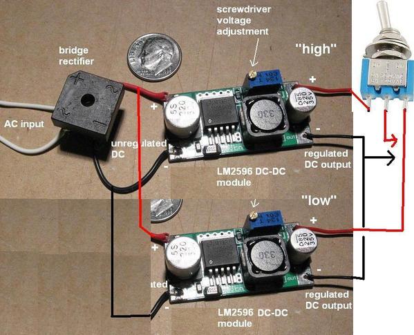
 

ogr lighting switched high low

And to egg you on a bit, what I'd really like to see is at least one of your stalls animated to open/close its doors.  There was this recent thread asking how to animate Korber RH doors and I excitedly cobbled together one suggestion with video on how it might be done but never heard back.  But as GRJ will remind me, Nothing is so easy as the job you imagine someone else doing!


Attachments

Images (2)
  • ogr rh relative lighting
  • ogr lighting switched high low

If you haven't already, I'd say sign up for the free The O Scale Resource online magazine.  Most of the stuff is way outside of what I'll ever do, but it's a nice read.  The most recent edition (Mar/Apr 2014) has an article on LED lighting, and the writer gives information how how he did his roundhouse, which sounds very much like how you'd like yours to be.  Click here to read it, and go to page 32 to start the article.  On page 38 he starts showing photos of his roundhouse and talking about what he did.

If you go to Ebay or Google " 12 volt led's " you will find dozens of offerings, many being marketed for automotive custom lighting.  Many offerings come from the Orient and are very cheap.  All kinds of lights and most will work on 12 v ac without problems.  You can buy led strips for a buck a foot cut them up and light dozens of projects. The prices and offerings are amazing and although delivery may take a few weeks, all have worked well for me.  Phil

Originally Posted by Laidoffsick:

It's just about time to add the lighting to this monster. I think I'm going with LED's, 3mm, flat top, warm white style. I'm looking to do it similar to the way that the Korber website roundhouse instructions show. I'm not an electrical guru so I'd like some opinions or ideas to best do it. You see the pic below, I plan to mount the LEDS to a Plsatruct lamp shade and then mount that to the side of the roof beams in each of the stalls. I'm looking at about 36 leds on the roof beams, plus 4 additional LEDs for the 4 doors on the RH.


Can all of these be powered from one 12 volt supply?


Do you think I would be better using the LED strips and have a dimmer installed as well? 


I'm curious what you guys think for lighting this thing. Thanks in advance for your help.


IMG_01281

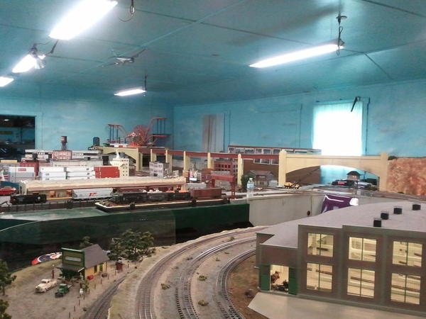
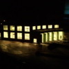
The roundhouse looks great. Dave O'Connor built ours and used LED strips. They're pre-configured for use with a 12-volt DC power source, are inexpensive, and easy to install. We've been switching our buildings over to these in place of incandescent bulbs. They're available in bright and warm white and work well as shown below:


You can see the lighting in the roundhouse at the lower right. Even in daylight with the lights on the lighting is good.

2012-05-02 17.21.31


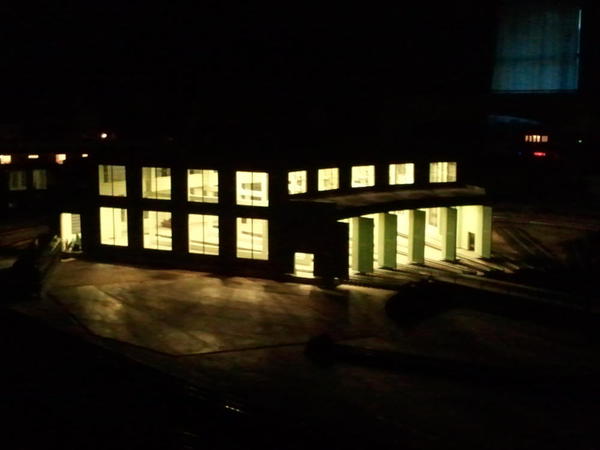
Here's a "night shot" of the roundhouse.

2012-03-10 18.10.40


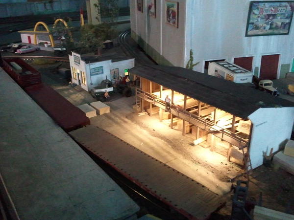
We also used them in the Walthers lumber shed.

2012-04-07 17.33.32

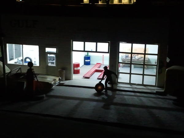
We used the bright white versions to light up this Berkshire Valley service station.

2012-03-10 18.10.31

Attachments

Images (4)
  • 2012-05-02 17.21.31
  • 2012-04-07 17.33.32
  • 2012-03-10 18.10.31
  • 2012-03-10 18.10.40
Originally Posted by Laidoffsick:
So I can use the ZW at full voltage and not drop the output of the converter down to12v? I thought the LED voltage had to be 12V.

Each LED operates at about 3V.  If your power source is 12V which of course is a commonly available voltage, then the common practice (as is done with LED strips) is to hook up 3 LEDs in series and add a 150 ohm resistor.  3 LEDs at 3V each plus the resistor at about 3V too add up to 12V.


The article was pointing out it might be easier to use assemble using the parallel method.  In this case the overhead bus wires carry 3V (plus or minus for brightness) and each LED connects in the same way.  The key is you have the voltage converter modules which can be adjusted to put out 3V.  By way of example, I showed how common LED flashlights use this same parallel method operating dozens of 3V LEDs where each LED connects to a common "bus" voltage.

I gotcha Stan, so if I run 20V, I could run a string of 6 LEDs based on a 3.2V per LED. Each string of LEDs in series, cannot surpass the max input voltage from my power supply.


I found the LED online calculator, or 1 of them, and have been playing with that. Calculates everything for me, and tells me what size of resistor to use.  

Last edited by Former Member

OK I've been thinking....again. If I wire 1 stall with 18 LEDs (9 on each side of the track), and wire them parallel, the current must be between 3v-3.5v on the bus wires right??


So I run the PW ZW into the converter module at 18v AC. The converter converts that to DC, and I dial the regulator down to 4v-4.5v and have a 1.5ohm resistor wired in to keep the power at 3v max?


How does that resistor get wired in the circuit?


Well, I'm glad the title of this thread asks for opinions as there are many options. 


If you've come around to the parallel bus method (instead of 12V strip method) and you are using a voltage regulator module, then my opinion is you don't need a resistor.  That is, you can set the voltage into each string to exactly 3.0 or 3.1 or whatever volts and it will work...end of story.  Driving a string at, say, 3.1V or less will insure you are not pushing the LEDs to their limit. 


If you want/need to push the LEDs to their rated maximum current then a resistor is a good idea as a sort of ballast.  A 1 ohm, 1 Watt resistor placed as shown would work.  Then you can put a voltmeter across the resistor to measure the voltage drop (which will tell you the current flowing) and you can adjust the module to whatever voltage puts the specified current. 


ogr rh led stall 

Note that in the case of the LED worklight I showed earlier, the starting voltage was 4.5V (and this changes as the battery drains) so it absolutely needs a method to ballast or drop the voltage.  But with a regulator module where you can exactly set the operating voltage, as long as you aren't pushing the LEDs to their limit, just operate them at about 10 or 15 mA average current and no resistor is needed...in my opinion of course.


And though it may mean a few more wires running between the RH and the base, I still think you ought to keep the wires to each stall separate so you can later add a circuit to sequence the stall lighting.  Now that's the video I'm waiting to see 


Attachments

Images (1)
  • ogr rh led stall
Last edited by stan2004
Originally Posted by Laidoffsick:
I wondered the same thing about the resistor. Do I really need it if I regulate the output current down to 3.5 volts? Although doing that, gives me no adjustability as far as dimming them down. I guess it's better to be safe than sorry, since it only requires 1 resistor wired in the + bus wire.


Your diagram shows a 1 ohm 1 watt resistor with 8 LEDs, so what would I need if my string has 16 LEDs? and dimming the lights is still a "must have".


In my opinion, if you have to ability to precisely regulate the voltage to 3.x Volts, then you do not need the resistor.  Limiting the voltage applied to an LED effectively limits the current.  Most LED applications start from a non-constant voltage (such as a battery) or from a constant voltage higher than the target voltage.  The higher constant voltage, 5V, 12V, whatever is usually a voltage of convenience fixed at that value for other reasons and now being called into service to drive LED(s) at a lower voltage via a resistor which effectively limits the current.


Not sure what you mean about dimming.  As shown earlier, whether you have a resistor in place or not you can always add yet more outside resistance (e.g., another 1 ohm resistor) to effect dimming.  Continuously variable dimming via a knob is a little trickier since variable resistors in the 1 ohm range are a not so common.  The "correct" way to do this is to tap into the LM2596 control circuit where you could then use a more common (higher ohm value) variable resistor but this is tomorrow's problem.  As suggested earlier you could simply use two modules, each set to slightly different voltages and switch between the two modules for high and low brightness.


The diagram was meant to represent all 18 LEDs. The dashes in the middle indicate more LEDs in there but I guess I should have just cut-and-pasted all 18 LEDs.


I've received all the parts except the LEDs of course. Apparently they were delivered to the wrong address. Tracking shows delivered last week, but not to my house anyway. I don't know where they went.


IMG_1458

Made a jig to hold the 60 lamp shades. They have to be drilled out to fit the 3mm LEDs.


IMG_1464

Had to hold them in my hand and drill them with 3 different bits to keep them from splitting. Rough on the fingers after 180 holes drilled.


IMG_1467

Painted the insides white to reflect the light and keep it from shining through the top. The outsides will get flat black.


IMG_1470

Attachments

Images (4)
  • IMG_1458
  • IMG_1464
  • IMG_1467
  • IMG_1470
Originally Posted by Laidoffsick:
I've received all the parts except the LEDs of course.

Of course.  All dressed up with no place to go.


So in the mean time, if you can't wait to mess with your LM2596 modules, I see the city you show in your profile has a Harbor Freight store.  If you're inundated with their coupons like I am (in the newspaper, magazines, etc.) you can get the worklight I show above and even a voltmeter FREE (no purchase required).


A guy in the subway forum is doing something similar with parallel LEDs to light up his tunnels.  As part of that discussion, I assembled the following photo showing a LM2596 module (one that has a voltmeter built-in) at a few select voltages driving the 24 parallel 5mm LED Harbor Freight worklight with no resistor.


ogr hf woklight 24 led

Attachments

Images (1)
  • ogr hf woklight 24 led

Funny you should mention that Stan, I just came in from the bench messing around with the converter modules, after returning from Radio Shack & Harbor Freight in the same shopping center. RS didn't have squat for LEDs, but I picked up a couple 5mm, 3V LEDs just to play with.


Just like you said, I really had to turn that output voltage adjustment screw several rotations to get any variation in the voltage, but once I did, I could dial in anything I wanted. After playing around with individual LEDs, a few different resistors, and adjusting the voltage up and down, I really like the parallel wiring without individual resistors on each LED, and just run the modules at 3.4v and lower for lower lighting. I guess 1 big resistor inline with the bus wire would be some protection against the very sensitive output adjustment screw. It will go fro 3v to 8v with half a turn.   

Last edited by Former Member

I'd seriously consider running them at a higher voltage and at least using one resistor for the parallel string.  If you put 4-5 volts on them for any length of time (seconds), you usually end up with dead LED's.  With a current limiting resistor, you minimize the chance of killing them.


If you have 10 LED's in parallel, you'd be looking at 200ma of current for full intensity.  A 10 ohm 1W resistor in series with the string of 10 would allow you to run them from a 5V power supply and also protect them from a small voltage mistake.


Not much time to today, gotta go bring a train down the pass. I did flip all the shades over and press them onto the upside down masking tape. That holds them so I can spray the black all at the same time without them blowing all over the floor.


Still waiting for the LEDs to show up.


IMG_1473

Attachments

Images (1)
  • IMG_1473
Last edited by Former Member

16 down, 64 to go  This is the front portion only.


IMG_20140503_165020_400

IMG_20140503_165139_389

IMG_20140503_180618_461

They are running through the converter module at 3.2v, with no resistor right now.


I put a 10 ohm 1 watt resistor inline with the module turned up to 5v, but they just weren't bright enough. I put the meter on the resistor and it showed only 2.5v.


So what do I adjust? Smaller or bigger resistor? I turned up the voltage at the module until I got 3v at the resistor, but it burned out the resistor and fried the 2 LEDs I had hooked up. That sucker was HOT!


I really do not want to burn these things out, but yet I want to run them at almost full current for max brightness. I can do that (I am doing that right now) with no resistor, like Stan mentioned, but I would like a sense of security from burning them out. I don't want to have to replace 16 at a time.    

Attachments

Images (3)
  • IMG_20140503_165020_400
  • IMG_20140503_165139_389
  • IMG_20140503_180618_461

Add Reply

Post

OGR Publishing, Inc., 1310 Eastside Centre Ct, Suite 6, Mountain Home, AR 72653
800-980-OGRR (6477)
www.ogaugerr.com

×
×
×
×
Link copied to your clipboard.
×
×