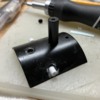
New thread for a new project - I'll be modifying a Weaver Baldwin Consolidation into a model of the New Haven's F-5 class.

Prototype background: In 1912, New Haven subsidiary Central New England Railway purchased 15 Consolidations from Alco. They were intended for drag freight service across the Maybrook Line (New Haven CT to Maybrook NY via Danbury CT and Poughkeepsie), which was just being assembled by the New Haven through consolidations and upgrades of existing disjointed routes. The Central New England owned outright the segment from Hopewell Jct, NY, through Poughkeepsie to Maybrook, and on October 1, 1912, the mountainous segment from Danbury to Hopewell Jct was also leased to them. Trains and locomotives operated though the whole route, and crews were split 50-50 between the New Haven proper and CNE.

By 1920, much larger L-1 class 2-10-2 engines had taken over most service on the Maybrook, and the CNE Consolidations were dispersed around the system. The freight roster was dominated by 2-6-0 Moguls, so the displaced Consolidations were useful as heavier local freight engines. They retained their Central New England lettering until the CNE was fully absorbed in 1927, and retained their numbers (150-164) through the end of steam service in 1950. Several spent their last years in local freight service out of Waterbury, where many great color photos were taken of them, a rarity for New Haven steam locomotives.

Not entirely set yet, but my model will most likely represent #153. This is one of the engines that had color photos taken in Waterbury, and it has the correct valve gear for the model. Many good black and white photos can be seen here: NYNH&H STEAM - CLASS F-5 2-8-0 (google.com)

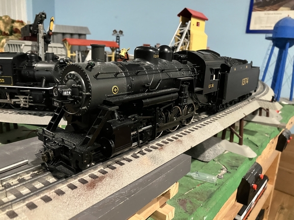
The Weaver Baldwin Consolidation is already a close match - changes needed on the engine include new marker lights and head light, modifying the firebox to the correct shape, adding arched cab windows, adding Alco builders' plates, and adding separate pilot support posts.

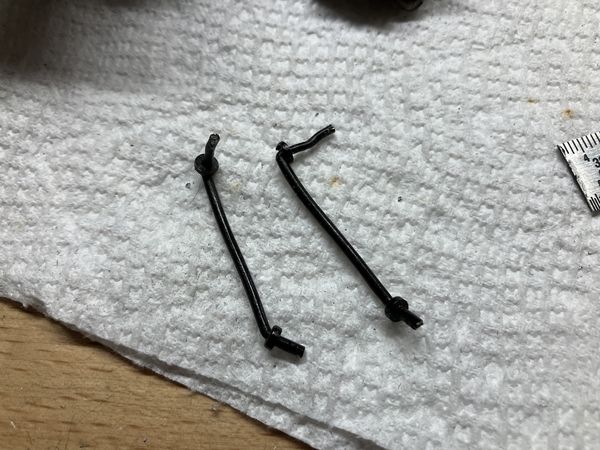
On the tender, changes include extended coal bunker sides that slope inward, electrical conduit run to the back headlight, and the addition of a polling pole and re-railers hung off the tender frame. Here is an example of some of those modifications I did to an 0-8-0 tender:

7 Example Tender Mods - conduit & polling pole

8 Example Tender Mods - rerailer

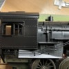
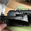
Here's my starting point:

2 Before 2

4 Before 45 Before 56 Before 6

1 Before 1

First thing to do is to open everything up and see how it ticks.

~Chris

Attachments

Images (7)
  • 1 Before 1
  • 2 Before 2
  • 7 Example Tender Mods - conduit & polling pole
  • 8 Example Tender Mods - rerailer
  • 4 Before 4
  • 5 Before 5
  • 6 Before 6
Original Post

Replies sorted oldest to newest

Thanks John and Dave. John - I am aware, but personally don't care for DCS, so it would have been a pass for me even if I didn't have this lined up already.

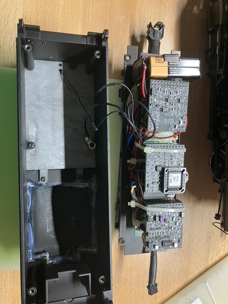
Disassembly has begun. The tender shell comes apart in two pieces, the main shell and the tender deck. The tender deck is freed up by removing four screws from the inside of the shell, as well as the rear ladder. The factory TMCC install takes up the entire tender. The 9 Volt battery had an expiration date of 2009, and was about to burst.

9 Tender Electronics 1

10 Tender Electronics 2

I keep track of screws as I remove them by sealing them in a painters tape packet, and labeling them. All the packets then go back into the engines box until needed for reassembly.

14 Screw Packet 1

i15 Screw Packet 2

No PCBs in the engine itself, just the motor and smoke unit. As far as puffer smoke units go I like Weaver's design, with the puffer driven directly from the gearbox.

12 Engine Insides 213 Engine Insides 3

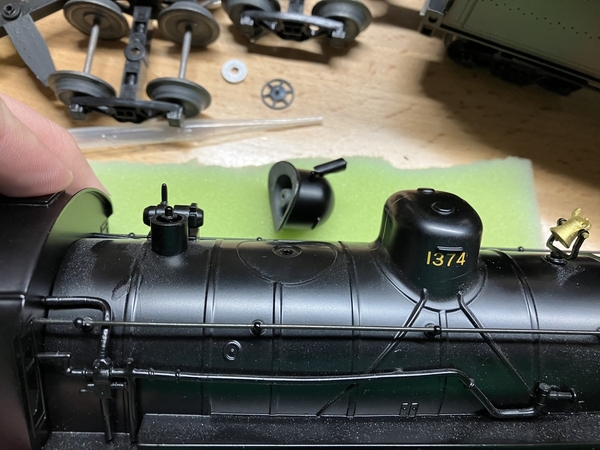
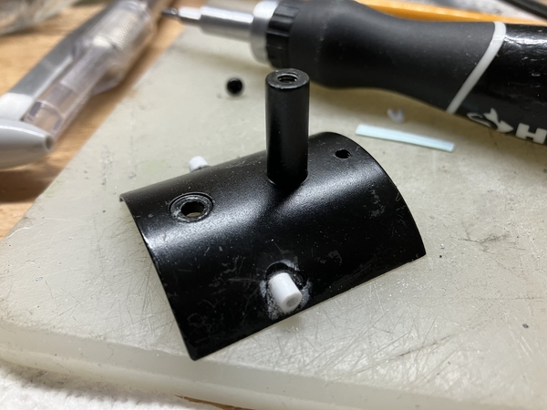
I discovered that the steam dome is actually a separately applied part and not integrated into the boiler casting, so I'm adding to my modifications list a shorter, less round dome to better match the prototype.

16 Dome 1

17 Dome 2

Lastly, I've decided to install Blunami in this engine, which will be my first time installing a control system other than TMCC. The greater variety of sounds is a huge draw for me, and I want to experiment with it to see how I like it vs TMCC/Legacy. The design of this engine mechanically also lends itself to a Blunami installation: wired tether between engine and tender, ample room in tender with an existing 8 ohm speaker installed, and a puffer smoke unit I can run directly off track power (as Blunami does not have an integrated smoke/chuff output).

Parts for the Blunami installation are ordered, and I'll most likely wire it up before or in parallel with the detailing.

~Chris

Attachments

Images (8)
  • 9 Tender Electronics 1
  • 10 Tender Electronics 2
  • 12 Engine Insides 2
  • 13 Engine Insides 3
  • 14 Screw Packet 1
  • 15 Screw Packet 2
  • 16 Dome 1
  • 17 Dome 2

Some interesting construction methods for diecast.  Almost seems like they made it sort of modular for changes in the future.  Chris, is the sand dome also removable ?

The Feb. issue of RMC had a cool kitbash what looks like the same Weaver model but in HO. I know it had a Baldwin builders plate. The author was modeling a Central Vermont 2-8-0. They were pretty cool looking with sort of a switcher style tender much like what your doing. He removed I think the sand dome and moved it forward and filled in the hole. They ran through MA. and Connecticut into the mid 50’s.
I wouldn’t spring for a new model to do this but wouldn’t mind bashing an older Weaver model into one. I did buy a custom run PDT CV caboose with no engine on the roster to pull it.

Dave - sand dome is not removeable, that one is cast in. I have some experience with diecasting, and as far as I can tell it is probably a separate piece because of mold flow issues the round dome top would have caused, or to make it easier to cast/drill the hole in the side of the dome for the whistle mount.

I do have that issue, and that was a great project to read about. The HO model is a Bachmann Spectrum engine, and I have seen a few people modify those into F-5's (and other prototypes) to varying degrees - it's an excellent representation of a 1910s/1920s Consolidation after a few upgrades.

A few years ago I came up with a list of engines that would be good starting points for accurate New Haven prototypes and I've been working my way though them:

1. USRA 0-8-0 into a New Haven Y-3 (USRA clone) - done, and whose tender I used as an example in the first post.

2. Lionel USRA 4-8-2 into an R-1-b - done.

3. Weaver 2-8-0 into an F-5 - in progress.

4. Lionel 2-6-0 into a K-1-b - engine acquired, no idea when I'll start it.

5. Lionel 4-4-2 into a F-1/H-1 - engine acquired, but on the far back burner since I also got the Legacy model cataloged a few years ago.


Bill - I've had your picnic in the back of my mind while planning this out, I'm not making any promises but having it ready by then is the goal. The Weaver drivetrain on this looks pretty solid, with very little wear. I'll service it (new grease and oil) but leave it as-is.

~Chris

Definitely a Kadee on the pilot, undecided on the tender. I have rolling stock with both lobster claws and Kadees so I may keep one of each. That being said, I'd appreciate it Hot Water if you'd refrain from starting unnecessary arguments in my thread; you often have great knowledge and information, but it's a shame you intermix it with bickering.

~Chris

I've separated the cab from the boiler shell and have been working on the cab details. I want to get the cab roughed in because it will eventually require to layers of paint; the first to give a smooth surface for rivet decals to be added, and then a finishing coat. I can work on the rivet decals in parallel with other parts of this project.

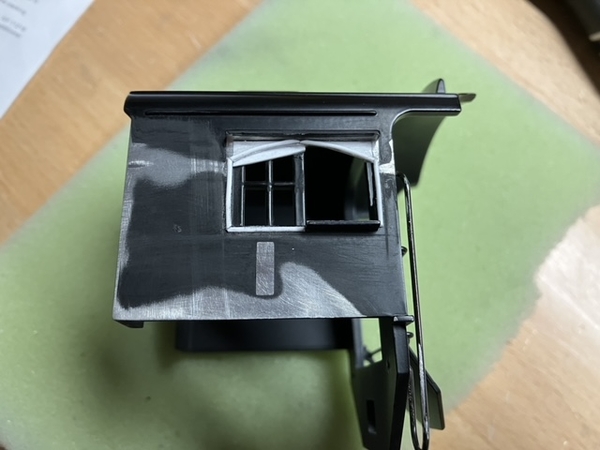
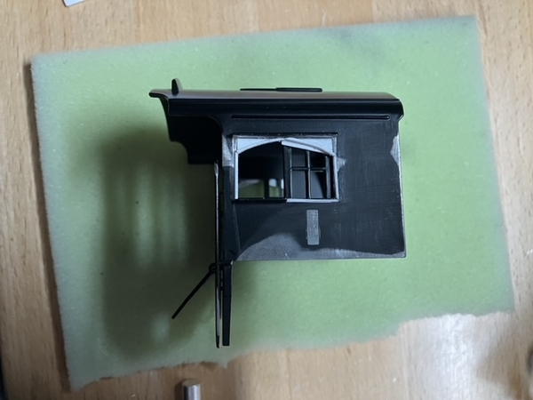
A few features from the cab sides were removed - there is a small rectangular protrusion under the cab window that had to go, as well as the corners of the rain guard that extended down the window frames. Engine #153 had a fairly large guard so I kept most of it - other F-5's had none at all.

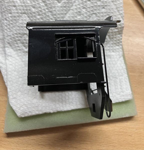
I then built up the arch at the top of the cab windows using layers of 0.020" thick styrene sheet. The whole window was then trimmed with 0.030" half round styrene rod. Arched cab windows were found on many New Haven steam engines, including all of the F-5 class.

18 Arch Cab Window 1

19 Arch Cab Window 2

20 Arch Cab Window 3

21 Arch Cab Window 4

While that was happening, I also began the Blunami installation. Old electronics in the tender were removed, including the speaker. The new speaker and baffle are from a Legacy Ten-Wheeler, and bolted right in place after enlarging two mounting holes in the chassis.

I followed the basic instructions in a Sid's Trains video for the Blunami installation. The setup is AC Track Power -> Rectifier -> Voltage Regulator (tuned to 20 Volts DC) -> Blunami input. The chassis was too narrow to mount both boards side by side at the same level, so the Blunami board is elevated on a styrene base made from I-beams and sheet. There is a gap down the middle, in-between the I-beams, for stashing a current keeper and running other wires through. I haven't connected the tether yet, so sound only, no motor or light controls.

~Chris

Attachments

Images (4)
  • 18 Arch Cab Window 1
  • 19 Arch Cab Window 2
  • 20 Arch Cab Window 3
  • 21 Arch Cab Window 4
Videos (1)
22 Blunami Sound Install

Anyone who's willing to attempt these kinds of alterations on a die-cast model has my profound respect!

From a mechanical standpoint, I'm pretty sure you'll get improved slow-speed operation if you can figure out a way to remove that crazy American Flyer-style puffing smoke system.  Two worm wheels are most decidedly NOT better than one!  Looking forward to more photos showing your continued progress.

Thank you Dave and Ted.

Ted - I definitely eased myself into cutting diecast. Not brave enough yet to cut apart brand new engines though. I'm going to do some test runs with the smoke unit in - the benefit to the gearbox driven unit is I don't need a secondary circuit to drive the smoke unit from the Blunami board - but if I don't like how the engine runs it'll go. Sounds are far more important to me than smoke.

Dave - I've been thinking about how to do this for quite a while. Building up layers with flat styrene was easy, but it wasn't until I got ahold of the half round dowels that I felt confident enough to pull it off. Adjusting them into place and curving the upper ones took some patience. I still need to fill and file the corners.

For reference, I had also considered cutting away all the window detail (leaving just a rectangular hole) and 3D printing a window insert. In the end I think this was easier. Still need to 3D print a new steam dome anyway.

~Chris

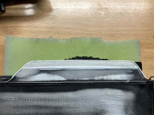
Progress on the tender; the USRA style tender that comes with the Weaver 2-8-0 has completely straight sides, while many New Haven tenders were built with sides that slope inward at the top of the coal bunker (or, for many smaller tenders, received extended sides later in service). I believe the F-5's tenders were built this way, as even the earliest prototype photos I can find show the tall coal bunker.

I built up the edges of the bunker with strip styrene, to the top of the slope sheet. The ends of the strip were then cut and sanded to approximate profile eventually needed - these will be fully formed after filler is applied and sanded smooth to hide the seam with the body.

23 Extended Coal Bunker24 Extended Coal Bunker25 Extended Coal Bunker

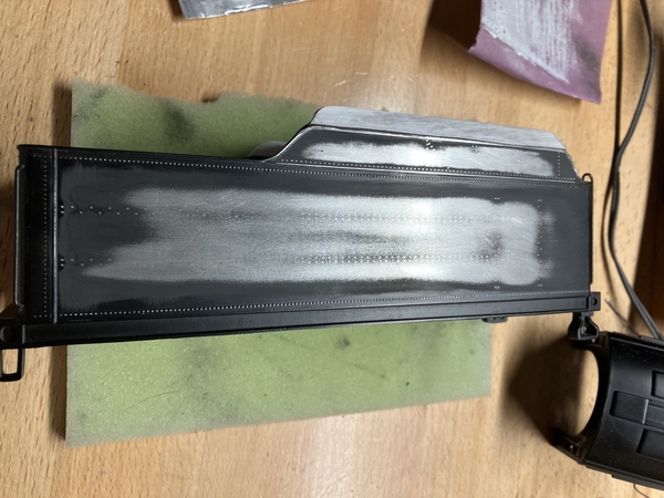
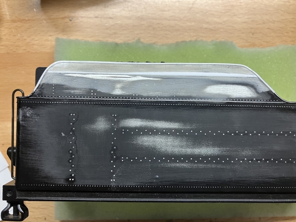
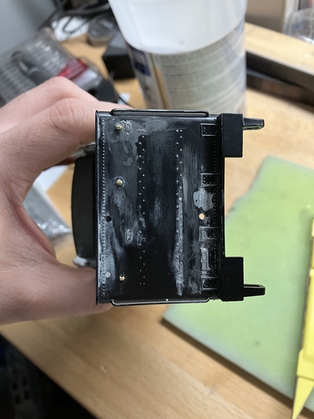
The rivet pattern on the tender was too far off the prototype, and with rivet decals readily available, they had to go. All rivets were sanded off both sides except for the bottom row, and the row level with the tender deck. Having the rivets extend properly into the extended sides should also help hide the fact they are an addition.

26 Tender Rivets Gone

~Chris

Attachments

Images (4)
  • 23 Extended Coal Bunker
  • 24 Extended Coal Bunker
  • 25 Extended Coal Bunker
  • 26 Tender Rivets Gone
@C.Vigs posted:

New thread for a new project - I'll be modifying a Weaver Baldwin Consolidation into a model of the New Haven's F-5 class.

Prototype background: In 1912, New Haven subsidiary Central New England Railway purchased 15 Consolidations from Alco. They were intended for drag freight service across the Maybrook Line (New Haven CT to Maybrook NY via Danbury CT and Poughkeepsie), which was just being assembled by the New Haven through consolidations and upgrades of existing disjointed routes. The Central New England owned outright the segment from Hopewell Jct, NY, through Poughkeepsie to Maybrook, and on October 1, 1912, the mountainous segment from Danbury to Hopewell Jct was also leased to them. Trains and locomotives operated though the whole route, and crews were split 50-50 between the New Haven proper and CNE.

By 1920, much larger L-1 class 2-10-2 engines had taken over most service on the Maybrook, and the CNE Consolidations were dispersed around the system. The freight roster was dominated by 2-6-0 Moguls, so the displaced Consolidations were useful as heavier local freight engines. They retained their Central New England lettering until the CNE was fully absorbed in 1927, and retained their numbers (150-164) through the end of steam service in 1950. Several spent their last years in local freight service out of Waterbury, where many great color photos were taken of them, a rarity for New Haven steam locomotives.

Not entirely set yet, but my model will most likely represent #153. This is one of the engines that had color photos taken in Waterbury, and it has the correct valve gear for the model. Many good black and white photos can be seen here: NYNH&H STEAM - CLASS F-5 2-8-0 (google.com)

The Weaver Baldwin Consolidation is already a close match - changes needed on the engine include new marker lights and head light, modifying the firebox to the correct shape, adding arched cab windows, adding Alco builders' plates, and adding separate pilot support posts.

On the tender, changes include extended coal bunker sides that slope inward, electrical conduit run to the back headlight, and the addition of a polling pole and re-railers hung off the tender frame. Here is an example of some of those modifications I did to an 0-8-0 tender:

7 Example Tender Mods - conduit & polling pole

8 Example Tender Mods - rerailer

Here's my starting point:

2 Before 2

4 Before 45 Before 56 Before 6

1 Before 1

First thing to do is to open everything up and see how it ticks.

~Chris

Fantastic, while companies may issue a “new” version. Nothing is as good as home built, nothing

Craig

PennCentralShops

Glad you're liking it Harley Rider!

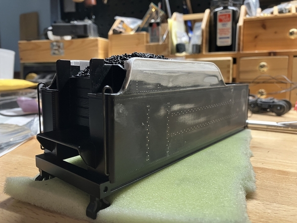
The coal bunker extensions have been finished - the joint and corners were filled with Bondo, sanded smooth, and the lip that follows the edge of the sheet metal added back in with more 0.030" half round styrene rod. I started with one end and glued the rod in place a few inches at a time, to use one continuous curved piece.

27 Extended Coal Bunker with Trim

28 Extended Coal Bunker with Trim

29 Extended Coal Bunker with Trim

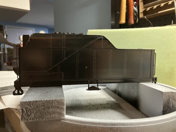
I then sketched a new rivet pattern for tender sides, as it would affect the placement of other details. Rivet pattern is roughed in from photographs - unfortunately, the tender typically isn't the subject matter when a photographer was looking at a steam locomotive, so locations are only approximate.

30 New Rivet Pattern

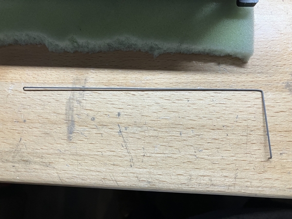
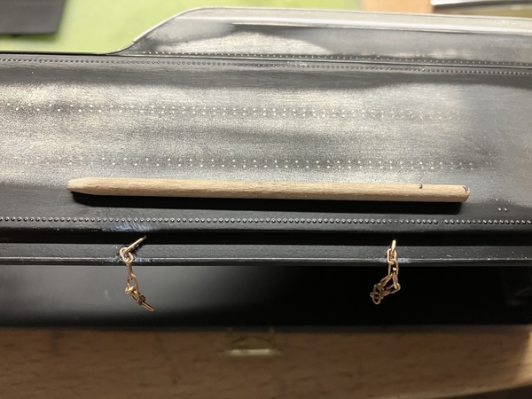
I then shaped a conduit that runs along the tender side to the rear headlight out of piano wire. This is the same method I used to make the conduit in the clear-vision tender in my original post. Tape holds it level to the tender for fitment and photo - it will be glued in place after the rivet decals are done.

31 Headlight Conduit

32 Headlight Conduit

~Chris

Attachments

Images (6)
  • 27 Extended Coal Bunker with Trim
  • 28 Extended Coal Bunker with Trim
  • 29 Extended Coal Bunker with Trim
  • 30 New Rivet Pattern
  • 31 Headlight Conduit
  • 32 Headlight Conduit

Chris, just fantastic modeling. The piano wire looks like you drilled 2 holes to mount it. What brand drill bit are you using  and what type of drill or pin vise ?  Diecast is fairly easy to drill if Your drilling and tapping for say a 2mm screw. Once you get into the numbered bits into the 60’s it gets a little tougher. I’ve had mixed success finding bits that work consistently.

I did drill two holes, with a #63 bit (IIRC) and a pin vise. I use a pin vise for most of my drilling into plastic and diecast for better control.

I've been using Excel brand drill bits for a few years - I have a set that has 20 or so bits in a protective plastic case with a base they all mount to. I did break one, but the rest are all still sharp, so I'd say it's my error and the quality is fine.

~Chris

Tender and cab are almost done now.

By the late 1940s, the F-5s were in switching and local service rather than the drag freights they had been built for. As such, the tenders were equipped with a polling pole (engineer's side) and re-railers (both sides). The pole is just a dowel that will have both ends chamfered, and then stained separately.

33 Enginers Side Tender Details34 Polling Pole

They were also long in the tooth, with many sheet metal patches. 153 had a large patch in the lower front corner of the fireman's side of the tender, which I've added with 0.010" styrene.

35 Firemans Side Tender Details

On the back of the tender, three flag holders were added. New mounting holes for the ladder were drilled to center it and the old ones filled.

36 Rear Tender Details

The headlight on the tender deck was removed, and a more accurate one will be added off-center. A continuation of the conduit from the tender side runs to the headlight mounting pad.

37 Tender Deck Details

The sheet metal on 153's cab also had sheet metal patches, three of them of different shapes and sizes. The cab also has a dusting of white primer on it - the primer helps to highlight areas that still need sanding.

38 Cab Patches

Full primer will be next, followed by a coat of black paint to lay the rivets down on.

~Chris

Attachments

Images (6)
  • 33 Enginers Side Tender Details
  • 34 Polling Pole
  • 35 Firemans Side Tender Details
  • 36 Rear Tender Details
  • 37 Tender Deck Details
  • 38 Cab Patches

Chris, your taking this project to the next level following pictures of the prototype with all the proper details. I’m blown away looking at the cab with the new arched windows and patched sheet metal. Looking forward to the next chapter in this project.

Is the re railer a brass detail item ?   I added a pole to a 10 Wheeler that late in life was used as a switcher. I’ll have to check the photo closer to see if it also had re railers.

Thank you very much Dave! It's the little details that give the model personality.

The re-railer is a casting from Precision Scale, #41108 "Rerail Frog with Hangers". It was common to hang the re-railers off the tender frame, close to the ground where they were needed, although I suppose they could be stored anywhere on the engine.

~Chris

Thank you very much for the compliment, Pat - hopefully you'll be able to see it firsthand at some point, maybe on a visit to Bill Park's. If you recall you sent me two sets of Alco builders' plates for my R-1 model; I have the other set earmarked for this guy.

Bill - that is still the goal! I've been making good progress, but I still need to hack apart the engine shell and paint/decal. I think it's doable, let's see what reality says.

I did begin wiring the engine tether back in, so I could test how the motor / geartrain behaves with the Blunami board. The speed control on Blunami is smooth as silk, at least on par with an ERR upgrade if not Legacy.

I did decide to remove the smoke unit though. When dry, the smoke unit provided very little resistance on the gear box and the engine ran smooth. After filled with fluid and running for a few minutes, the engine would almost come to a stop when the piston in the puffer unit reached top-dead-center. When the piston was removed, fluid came out of the cylinder, so either one of two things is happening: I used too much fluid and it worked its way into the cylinder, or the piston is pulling smoke into the cylinder and it is condensing, resulting in trying to compress an incompressible fluid.

I'm not crazy for smoke units to begin with so out it came. A fan driven smoke unit may go in there one day. For anyone's future reference, the connecting rod to the piston is attached to a spur gear with a shouldered screw, under the plastic gearbox cover.

~Chris

Chris, great work here. FWIW I did a K-line semi scale Mikado that had one of those piston smoke units and replaced it with a fan unit. I used the gear that drives the piston and installed four Allen cap screws in the side of the gear at 90 degree increments to operate a micro switch to drive the fan 4 times per driver rev.
It won’t always be in perfect sync with the chuff sound but usually its close enough.

This as an alternative to continuous smoke should you opt for that.


Pete

That's a good idea Pete - I'll keep an eye out for a good fan driven smoke unit or wait until Lionel's part sale.

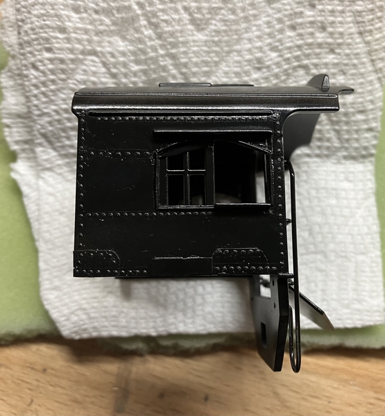
I had given the cab a coat of Tru Color black yesterday, to get a surface to apply the rivet decals on. This morning I laid out and applied the rivets on both cab sides. It will need another coat of black on top of the rivets to seal them in.

First coat of paint:

39 Cab 1st Paint

Rivets laid out - I also cut out the cab numbers, just to gauge how they would fit:

40 Cab Rivet Layout

Rivets applied, both sides:

41 Firemans Side Cab Rivets42 Engineers Side Cab Rivets

~Chris

Attachments

Images (4)
  • 39 Cab 1st Paint
  • 40 Cab Rivet Layout
  • 41 Firemans Side Cab Rivets
  • 42 Engineers Side Cab Rivets

The cab has been given another coat of black to seal the rivet decals in and is looking pretty good.

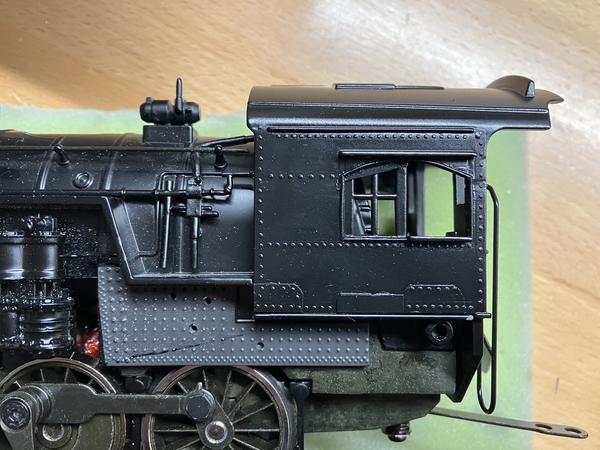
43 Finished Cab & Original Firebox Engineers Side

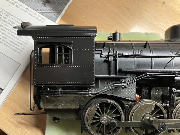
44 Finished Cab & Original Firebox Firemans Side

The cab was temporarily mounted on the boiler while I figured out how to cut down the firebox; the generic Baldwin Consolidation has a flat bottomed firebox, while the F-5s sloped upwards (over the rear wheel) with obvious ash pans.

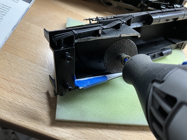
I ended up cutting a piece of thick styrene to the profile of the section I wanted to remove, by laying it over the outside of the firebox. I then taped it to the inside edge, and used it as a guide for cutting blind with my Dremel tool. The photos below demonstrate the process.

45 Firebox Cut Pattern

46 Pattern in use 1

47 Pattern in use 2

Comparison photos with the first two, to show the new firebox shape relative to the cab:

49 Finished Cab & Cut Firebox Engineers Side

50 Finished Cab & Cut Firebox Firemans Side

It was actually a huge relief to get through this part, as I thought this would be the most difficult and drastic change to the shell casting.

I need to make an ash pan next, and the first revision of the new dome should be arriving from the 3D printer soon.

~Chris

Attachments

Images (8)
  • 43 Finished Cab & Original Firebox Engineers Side
  • 44 Finished Cab & Original Firebox Firemans Side
  • 45 Firebox Cut Pattern
  • 46 Pattern in use 1
  • 47 Pattern in use 2
  • 48 Rough Cut
  • 49 Finished Cab & Cut Firebox Engineers Side
  • 50 Finished Cab & Cut Firebox Firemans Side

I received the initial print of the new steam dome from Shapeways. It fits the boiler well, however after comparing to prototype photos it does need to be shorter and flatter on top. I made the modifications to my 3D model and ordered another one. The material is Shapeways 'Fine Detail Plastic', which used to only come in a translucent form but now also has this cheaper tan option. 

51 Dome Rev 1 1

52 Dome Rev 1 2

Decals have been added to the tender sides as well. Each side took about 2 hours. The rivet decals, when used as a single row, have a tendency to tear when applying a long strip. Several of the long single rows are actually 4 or 5 pieces realigned after application, but I don't think it shows.

53 Tender Rivets 1

54 Tender Rivets 2

The ash pans are starting to come together, both as an added detail and a nice way to hide the cut edge of the Firebox.

55 Firebox Ash Pan

Finally, I began installing the pilots support poles that the F-5s featured. One of the first actions on my R-1b Mountain build was to remove pilot supports from the Lionel USRA Mountain I used, and I figured this would be a good reuse of those parts. I first drilled holes in the pilot, located per prototype photos.

56 Pilot Support Pole Holes

The pilots supports from the Lionel USRA Mountain:

57 Pilot Support Poles from USRA Mountain

Added mounting points on the underside of the boiler using styrene tube:

58 Tube on Underside Boiler

The pilot supports installed temporarily:

59 Pilot Support Poles in Place

I actually dislike how the supports look. In order to accommodate the design of the Lionel supports, which have a right angle jog at the top to fit into the mounting holes, they end up angled slightly outward. Prototype photos show them almost completely straight. I had hoped it wouldn't be that noticeable, but once you see a flaw in your own work...

I'm going to experiment with different configurations for the supports. I'm thinking I can make better straight ones out of styrene shapes.

~Chris

Attachments

Images (9)
  • 51 Dome Rev 1 1
  • 52 Dome Rev 1 2
  • 53 Tender Rivets 1
  • 54 Tender Rivets 2
  • 55 Firebox Ash Pan
  • 56 Pilot Support Pole Holes
  • 57 Pilot Support Poles from USRA Mountain
  • 58 Tube on Underside Boiler
  • 59 Pilot Support Poles in Place

Add Reply

Post

OGR Publishing, Inc., 1310 Eastside Centre Ct, Suite 6, Mountain Home, AR 72653
800-980-OGRR (6477)
www.ogaugerr.com

×
×
×
×
Link copied to your clipboard.
×
×