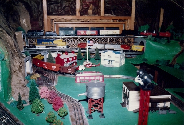
Hi everyone!

Just got my postwar collection out of mothballs after 30 years in storage. I caught the bug and have started building a layout in the attic. My father, who is now 90, recently spent a week cramped in the attic with me helping me lay track. It is the father-son project we didn't finish in 1985 and I'm grateful we are finally

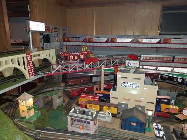
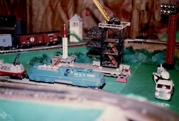
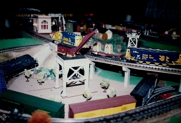
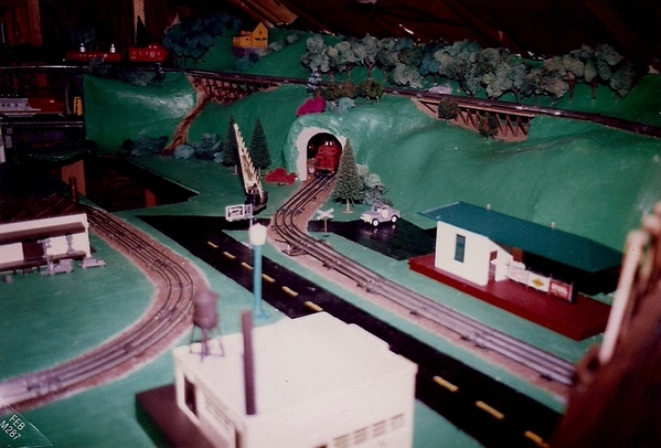
The layout is a dog bone, 40' x 9', with two loops and a switch yard, and with the main line elevating 5" to clear a floor joist at both ends. It is still a work in progress (see pictures). You'll notice I still have not put down track bed or anything, but I at least have the outer loop up and running so can run trains with my kids (5 and 10, they love it!).

My goal is to keep things simple. I have a ZW and would like post D to run the outer (main) line, and post A to run the inner line and switch yard. That way I can have two trains running at the same time in separate districts but without the complication of blocks. I may add blocks at some point later. Switches will be constant voltage from post B and lighted accessories will be constant voltage from post C.

I also plan to have a crossover between the loops, and here is where I have a question. After looking at length on this and other forums, I have read several places that bridging the two districts when the two sides of the ZW are at different voltages creates a dangerous fault current. Some years ago, a poster named Bob Nelson wrote:

I would advise you to arrange your transformer connections so that you can power both loops from the same transformer output terminal when crossing between loops.  You can do this with a single-pole-double-throw switch to connect the center rail of each loop to either A or D.  (Or even leave one loop's center rail permanently connected to, say, A, and use just one SPDT switch to connect the other loop to A or D.)

The reason for this is that, if you neglect to set the A and D controls nearly exactly to the same voltage, a large fault current will flow as the locomotive (or lighted-car) pickups connect the two loops together when traveling through your crossover.  This current does not flow through the circuit breaker, so it will not trip to protect your transformer.

I wonder if someone could please walk me through exactly how to wire this up. Do I run power directly from each ZW post to the SPDT switch, and then to the track? Forgive the novice question - my learning curve is steep!

In any case, thrilled to be back in the hobby and thanks in advance for your input/feedback.

Kevin

IMG_8449

IMG_8450IMG_8451IMG_8452

Attachments

Images (4)
  • IMG_8449: Looking west to switch yard
  • IMG_8450
  • IMG_8451
  • IMG_8452: Looking east to countryside
Videos (1)
IMG_8392
Original Post

Replies sorted oldest to newest

First and foremost, WELCOME to the Forum! You will find a lot of great advice and how-to here. And we will be more than willing to help you climb that learning curve. We've all been there, done that (BTDT)!

Second, congratulations on having your 90 year old father help you with all of this! That is extremely impressive! (I wish my Dad was still around to help me!)

Third, it looks like you have a great start to the layout. Congratulations on identifying a space for a layout. That's always a tough one. I do have a question for you on it though. Give or take a bit, where are you located geographically? How hot or cold does it get in the attic? If either are major extremes, you may want to consider insulation and some lighting before you go much further. Unless this is a temporary setup and you are moving the layout elsewhere in the near future. I know summers and winters in the northeast can be really rough when you are in an uninsulated attic. (Don't ask me how I know this...) 

Fourth, to answer your question, on the ZW there is are 2 rings, one between the A handle and the B handle, the other between the C handle and the D handle. One each are a pair of black and a red marks. With all 4 handles down (no voltage) look where the zero marks are on each side. One will line up with the red, and the other with the black. Lets say the A handle line zero lines up with the red mark (could be the other way around). The B will line up with the black. Same thing on the other side. When you cross from one circuit to the other, just match the marks for the A and D handles. You might be off a bit, but you will be close enough not to have an issue. You will need insulating pins on the center rails of the crossovers. Whatever you do, DO NOT pull the insulating pins from the common rails of the switches! Those are needed to operate the non-derailing function of the switches. Depending on exactly what you want to do with train operation, a SPDT may or may not be necessary.

Fifth, what can you tell us about the green AA Alco diesels? 


Chris

LVHR

Last edited by lehighline
Leroof posted:

Welcome,  Kevin, that GG 1 is hauling a SERIOUS train!

That must be a 2340 or 2360 !

Awesome. all our collective best to you , your 90 year old  dad and the kids.

lots of fun to be had. Plus someone knowlegable in lionel wiring will step up to help I am sure. 

Keep up the good work

Leroof

Yes, it's a 2340. Unbelievable puller. Leaves my F3s in the dust. I can start with the engine on the steepest part of the grade (3.5%) from a dead stop pulling 30 cars, and it barely spins a wheel. It's truly a postwar marvel.

lehighline posted:

First and foremost, WELCOME to the Forum! You will find a lot of great advice and how-to here. And we will be more than willing to help you climb that learning curve. We've all been there, done that (BTDT)!

Second, congratulations on having your 90 year old father help you with all of this! That is extremely impressive! (I wish my Dad was still around to help me!)

Third, it looks like you have a great start to the layout. Congratulations on identifying a space for a layout. That's always a tough one. I do have a question for you on it though. Give or take a bit, where are you located geographically? How hot or cold does it get in the attic? If either are major extremes, you may want to consider insulation and some lighting before you go much further. Unless this is a temporary setup and you are moving the layout elsewhere in the near future. I know summers and winters in the northeast can be really rough when you are in an uninsulated attic. (Don't ask me how I know this...) 

Fourth, to answer your question, on the ZW there is are 2 rings, one between the A handle and the B handle, the other between the C handle and the D handle. One each are a pair of black and a red marks. With all 4 handles down (no voltage) look where the zero marks are on each side. One will line up with the red, and the other with the black. Lets say the A handle line zero lines up with the red mark (could be the other way around). The B will line up with the black. Same thing on the other side. When you cross from one circuit to the other, just match the marks for the A and D handles. You might be off a bit, but you will be close enough not to have an issue. You will need insulating pins on the center rails of the crossovers. Whatever you do, DO NOT pull the insulating pins from the common rails of the switches! Those are needed to operate the non-derailing function of the switches. Depending on exactly what you want to do with train operation, a SPDT may or may not be necessary.

Fifth, what can you tell us about the green AA Alco diesels? 


Chris

LVHR

Hi Chris - thanks for the warm welcome! I am in a very mild climate here in Central California on the coast, so short of putting in a dehumidifier for a couple of foggy months, I shouldn't need much else up there. I'll close off the vents at each end in the winter.

Great advice on the ZW - I was wondering if that were possible, but wasn't sure. I would be fine with that solution (and may go that route initially), but I worry about my two little ones running the trains and not  syncing up the voltages and causing some damage or worse, a fire. I like the idea of a solution that is a bit more foolproof, such as adding a toggle to run the whole mess from one side of the Z.. but I just don't exactly understand how to do it.

Thanks again and I look forward to tuning into the community!

Hi Kevin! welcome aboard, very cool attic layout, I'll bet you and your family will have a great time!.....one neat feature of this forum, up at the top you will see search in the tool bar, you can search topics such as your crossover question, and find the answers you are looking for that will best suite your particular application......oh, and I'm digging the tank car train in the back!....……………………...Pat

Last edited by harmonyards
CoastsideKevin posted:
lehighline posted:

First and foremost, WELCOME to the Forum! You will find a lot of great advice and how-to here. And we will be more than willing to help you climb that learning curve. We've all been there, done that (BTDT)!

Second, congratulations on having your 90 year old father help you with all of this! That is extremely impressive! (I wish my Dad was still around to help me!)

Third, it looks like you have a great start to the layout. Congratulations on identifying a space for a layout. That's always a tough one. I do have a question for you on it though. Give or take a bit, where are you located geographically? How hot or cold does it get in the attic? If either are major extremes, you may want to consider insulation and some lighting before you go much further. Unless this is a temporary setup and you are moving the layout elsewhere in the near future. I know summers and winters in the northeast can be really rough when you are in an uninsulated attic. (Don't ask me how I know this...) 

Fourth, to answer your question, on the ZW there is are 2 rings, one between the A handle and the B handle, the other between the C handle and the D handle. One each are a pair of black and a red marks. With all 4 handles down (no voltage) look where the zero marks are on each side. One will line up with the red, and the other with the black. Lets say the A handle line zero lines up with the red mark (could be the other way around). The B will line up with the black. Same thing on the other side. When you cross from one circuit to the other, just match the marks for the A and D handles. You might be off a bit, but you will be close enough not to have an issue. You will need insulating pins on the center rails of the crossovers. Whatever you do, DO NOT pull the insulating pins from the common rails of the switches! Those are needed to operate the non-derailing function of the switches. Depending on exactly what you want to do with train operation, a SPDT may or may not be necessary.

Fifth, what can you tell us about the green AA Alco diesels? 


Chris

LVHR

Hi Chris - thanks for the warm welcome! I am in a very mild climate here in Central California on the coast, so short of putting in a dehumidifier for a couple of foggy months, I shouldn't need much else up there. I'll close off the vents at each end in the winter.

Great advice on the ZW - I was wondering if that were possible, but wasn't sure. I would be fine with that solution (and may go that route initially), but I worry about my two little ones running the trains and not  syncing up the voltages and causing some damage or worse, a fire. I like the idea of a solution that is a bit more foolproof, such as adding a toggle to run the whole mess from one side of the Z.. but I just don't exactly understand how to do it.

Thanks again and I look forward to tuning into the community!

Oh, about the green Alcos - funny you should mention that as that just happened today. Last week I got my absolute all time favorite Alco 2023s back from servicing, and I had a set of scrap shells lying around. I asked my 5 year old son if he wanted his own train now, and of course he said yes! So I told him he could have any color he wanted, and he chose green. The only color green spray paint I had was what I used on the layout, moss green. So moss green he got, and he loves it! My daughter wants a purple train, so my scrap shells for my 2343 F3s are about to turn lavender! Will have to post a picture of that, too.. haha.

harmonyards posted:

Hi Kevin! welcome aboard, very cool attic layout, I'll bet you and your family will have a great time!.....one neat feature of this forum, up at the top you will see search in the tool bar, you can search topics such as your crossover question, and find the answers you are looking for that will best suite your particular application......oh, and I'm digging the tank car train in the back!....……………………...Pat

Thank you, Pat. That's a brand new-to-me 675 pulling the tanks with ease. Lovin' it! I feel like a kid again!

CoastsideKevin posted:
lehighline posted:

Fourth, to answer your question, on the ZW there is are 2 rings, one between the A handle and the B handle, the other between the C handle and the D handle. One each are a pair of black and a red marks. With all 4 handles down (no voltage) look where the zero marks are on each side. One will line up with the red, and the other with the black. Lets say the A handle line zero lines up with the red mark (could be the other way around). The B will line up with the black. Same thing on the other side. When you cross from one circuit to the other, just match the marks for the A and D handles. You might be off a bit, but you will be close enough not to have an issue. You will need insulating pins on the center rails of the crossovers. Whatever you do, DO NOT pull the insulating pins from the common rails of the switches! Those are needed to operate the non-derailing function of the switches. Depending on exactly what you want to do with train operation, a SPDT may or may not be necessary.

Chris

LVHR

Great advice on the ZW - I was wondering if that were possible, but wasn't sure. I would be fine with that solution (and may go that route initially), but I worry about my two little ones running the trains and not  syncing up the voltages and causing some damage or worse, a fire. I like the idea of a solution that is a bit more foolproof, such as adding a toggle to run the whole mess from one side of the Z.. but I just don't exactly understand how to do it.

Thanks again and I look forward to tuning into the community!

Kevin, I also welcome you to this Forum, which has been a source of joy, happiness and valuable information since I joined it one year ago.

One comment about your idea of adding a toggle to run both loops of track "from one side of the Z,"  I believe if you do that, one drawback would be that you won't be able to independently control the 2 trains, one on the inner loop, and the other on the outer loop, of track. 

I have a 25 year old conventional layout with tubular track and 022 switches, and 2 loops of track interconnected with switches in two different locations. Each loop is independently controlled, one from the A Post, and the other from the D Post, of a ZW, and I use fiber pins at the point between the switches where the 2 loops meet.

When I am running one train through the switches where the 2 loops meet, I set the voltage so its approximately the same on each loop, and I have never had a problem. Be that as it may, I can certainly understand your concern when young children are running the trains, especially if there may be occasions that you are not supervising them.  Arnold

Arnold D. Cribari posted:
CoastsideKevin posted:
lehighline posted:

Fourth, to answer your question, on the ZW there is are 2 rings, one between the A handle and the B handle, the other between the C handle and the D handle. One each are a pair of black and a red marks. With all 4 handles down (no voltage) look where the zero marks are on each side. One will line up with the red, and the other with the black. Lets say the A handle line zero lines up with the red mark (could be the other way around). The B will line up with the black. Same thing on the other side. When you cross from one circuit to the other, just match the marks for the A and D handles. You might be off a bit, but you will be close enough not to have an issue. You will need insulating pins on the center rails of the crossovers. Whatever you do, DO NOT pull the insulating pins from the common rails of the switches! Those are needed to operate the non-derailing function of the switches. Depending on exactly what you want to do with train operation, a SPDT may or may not be necessary.

Chris

LVHR

Great advice on the ZW - I was wondering if that were possible, but wasn't sure. I would be fine with that solution (and may go that route initially), but I worry about my two little ones running the trains and not  syncing up the voltages and causing some damage or worse, a fire. I like the idea of a solution that is a bit more foolproof, such as adding a toggle to run the whole mess from one side of the Z.. but I just don't exactly understand how to do it.

Thanks again and I look forward to tuning into the community!

Kevin, I also welcome you to this Forum, which has been a source of joy, happiness and valuable information since I joined it one year ago.

One comment about your idea of adding a toggle to run both loops of track "from one side of the Z,"  I believe if you do that, one drawback would be that you won't be able to independently control the 2 trains, one on the inner loop, and the other on the outer loop, of track. 

I have a 25 year old conventional layout with tubular track and 022 switches, and 2 loops of track interconnected with switches in two different locations. Each loop is independently controlled, one from the A Post, and the other from the D Post, of a ZW, and I use fiber pins at the point between the switches where the 2 loops meet.

When I am running one train through the switches where the 2 loops meet, I set the voltage so its approximately the same on each loop, and I have never had a problem. Be that as it may, I can certainly understand your concern when young children are running the trains, especially if there may be occasions that you are not supervising them.  Arnold

Thank you, Arnold. Glad you hear you have successfully used that system to transfer between loops, too. I think the idea with the toggle is that you set it up so one side of the Z controls both districts for only as long as it takes for the entire train to crossover. Then, toggle to the other side and you’re back in two train, manual control mode. 

By the way, I have been watching all the activity on your thread Postwar Paradise and very much enjoying it. That’s what I came here for! Will also try to post a little video to add to the fun. 

All best wishes,

Kevin

I join the guys in welcoming you, Kevin.

I love attic layouts. Agree with Chris about how to set up and run trains through your crossover.  I still have my two remaining conventional lines set up that way.  The lowest two levels in this pic show the conventional lines that run through two more rooms.  They are insulated against each other.

20181028_012740

These are a few pics of my old attic layout.  In CT, it was cold in mid-winter and hot in mid-summer.  Thirty years ago, I didn't seem to mind.  I also didn't mind that the table of nine four by eights was only two feet high, to save on the supporting two by fours.  There was a LOT of crawling around in those days.  This one was also done with a lot of help from my father, who had constructed two layouts in our old house.  It was 22 years between this one and those two.

20001

40001

140001

80001

Best wished for your new project, and keep us posted.

Jerry

Attachments

Images (5)
  • 20001
  • 40001
  • 140001
  • 80001
  • 20181028_012740
JerryG posted:

I join the guys in welcoming you, Kevin.

I love attic layouts. Agree with Chris about how to set up and run trains through your crossover.  I still have my two remaining conventional lines set up that way.  The lowest two levels in this pic show the conventional lines that run through two more rooms.  They are insulated against each other.

20181028_012740

These are a few pics of my old attic layout.  In CT, it was cold in mid-winter and hot in mid-summer.  Thirty years ago, I didn't seem to mind.  I also didn't mind that the table of nine four by eights was only two feet high, to save on the supporting two by fours.  There was a LOT of crawling around in those days.  This one was also done with a lot of help from my father, who had constructed two layouts in our old house.  It was 22 years between this one and those two.

20001

40001

140001

80001

Best wished for your new project, and keep us posted.

Jerry

Thanks so much, Jerry. I love seeing all these pictures. Your current layout is so cool! How many rooms in the house does it span?

Add Reply

Post

OGR Publishing, Inc., 1310 Eastside Centre Ct, Suite 6, Mountain Home, AR 72653
800-980-OGRR (6477)
www.ogaugerr.com

×
×
×
×
Link copied to your clipboard.
×
×