
Thanks guys, I'm hoping that soon I'll have lots more videos of more of the dusty stuff on all the shelves and in all the boxes!

@Dave Funk posted:

Congats on your first run!!

Another 2 weeks and the whole layout will be completed!

Thanks, but the only way this gets done in two weeks is if 20 people show up and all work together!

John, I know you going to be running 'modern' controllers (radio/computer etc.) switch/block system... but, are you going to build an old school control panel as well?

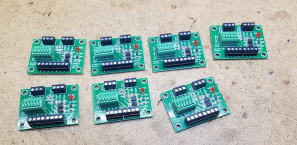
I will have a control panel with the switches and turntable controls.  However, all the power districts, sidings, switches, and the turntable will be TMCC controlled.  I should be able to run pretty much everything from the TMCC/Legacy remote.  I have a box of Lionel SC2 controllers that have been waiting for something to do, they're getting their chance now!

Wow, this is a very nice video, it’s a really nice long smooth run and I’m so glad you were able to do such a great job laying track. Fantastic work. You shouldn’t have many derailments that are track related. Your layout will be lots of fun to run. Thank you very much for this cool video. Do you have a name for your layout? It’s going to be fun work from now on as trains will be involved with testing during your wiring process. It’s all the fun of the game. Congratulations on the maiden run and we look forward to your progress. Happy Railroading Gunrunner John.

WOW, thanks for all the nice comments.  I'm pretty happy with the progress, I just wish it could go faster.   Of course, I already know things I might have done differently, but I guess that's always the way.  I'm already thinking about making the wiring a bit easier.

In looking at the benchwork, I realize that once the whole layout is on it, and the legs are firmly seated on the floor (in the carpet), there's no way the legs are going to move.  So, what's with all the extra cross-members that just make it a PITA to scoot around and do the wiring?   I think the two with the XX will be the first to go.

Attachments

Images (1)
  • mceclip0

WOW, thanks for all the nice comments.  I'm pretty happy with the progress, I just wish it could go faster.   Of course, I already know things I might have done differently, but I guess that's always the way.  I'm already thinking about making the wiring a bit easier.

In looking at the benchwork, I realize that once the whole layout is on it, and the legs are firmly seated on the floor (in the carpet), there's no way the legs are going to move.  So, what's with all the extra cross-members that just make it a PITA to scoot around and do the wiring?   I think the two with the XX will be the first to go.

And John you can always re-install those X members after the bulk of the wiring is done, if you judge they are needed. But they will also make storage of "stuff" under the layout very difficult.

As some guy once said "Nothing is as easy as the job you imagine someone else doing!" Very true words. It seems all projects take a lot longer and cost a lot more than you thought they would.

Rod

John I just watched your mobius video of the first run. Very nice and that track plan should provide lots of great running. Aside, I noticed a familiar looking guy standing at the foot of the stairs! Another thing I noticed is that workbench is far too clean. How does that happen when you are knee-deep into layout building? Haha.

Rod

Last edited by Rod Stewart

Actually, you can't really "install" the cross members after the fact, you have to install them as you build.  The only way to get them in after the fact is to loosen up the top structure (not recommended!!!) so you could move the legs out far enough to go over the studs that screw into the legs.  The only way to get them out is cut them and then remove the two halves, that's my method.

In any case, four of them are gone.  I went under and I can't move the legs with all the weight on them, they're sitting in cups that have grippers into the carpet so they can't shift.  That being the case, I can't imagine it being an issue without some of these supports.  I don't see any issue in removing any of these that get in my way.  As I work, a couple more may get sacrificed, the layout ain't going anywhere at this point!  If, for some reason, there was a reason to add such bracing back in, I could just use some standard 2x4 lumber and run the screws all the way through the legs to install them.  I'm not anticipating having to do this, but there's always a way to skin the cat if necessary.

@Rod Stewart posted:

John I just watched your mobius video of the first run. Very nice and that track plan should provide lots of great running. Aside, I noticed a familiar looking guy standing at the foot of the stairs! Another thing I noticed is that workbench is far too clean. How does that happen when you are knee-deep into layout building? Haha.

I cleaned off the workbench just for the video!

Me too, and it won't be that long now!   Too bad I couldn't fit a bigger turntable in so it could live on the layout full time, maybe I'll park it on one of the hidden sidings.

I'm already thinking about a lower level yard, I've been chatting with my carpenter friend about how that might be grafted into the layout.  It may be more than I want to tackle until I get farther along, we'll see...

Last edited by gunrunnerjohn

Me too, and it won't be that long now!   Too bad I couldn't fit a bigger turntable in so it could live on the layout full time, maybe I'll park it on one of the hidden sidings.

I'm already thinking about a lower level yard, I've been chatting with my carpenter friend about how that might be grafted into the layout.  It may be more than I want to tackle until I get farther along, we'll see...

Come on John... break out the sawzall  and cut the hole for the lower level yard. Tom will figure it out. Charge forward....dont look back. 😂😂

Hi John. Your layout is looking great so far. Can't wait to see it with scenery. I did notice one thing that I hope won't come back to bite you. Hopefully you will have access to the hidden switches on the lower loop. The way my luck goes one of them would be the first to fail. I can only wish I had the space that you have for a future layout. Hoping to win the lottery but keep forgetting to play. Keep up with the good work. Again looking very nice.

@Rod Stewart posted:

As some guy once said "Nothing is as easy as the job you imagine someone else doing!" Very true words. It seems all projects take a lot longer and cost a lot more than you thought they would.

Just because its a bad idea doesn't mean it might not be fun!....

"“This is the best bad idea we have, sir,”

Salute Rod, Even those ideas...were FUN! Like my Wooden Trestle! HA, fun for a week solid, still a bad idea. Cheers

@hokie71 posted:

I have a theory.  There is no way there is only one GRJ who answers all of these comments and then gets anything done on the new  layout, repairs items, responds to other threads, Henning's, etc.  There are multiple individuals, like Santa's elves in the GRJ workshop, and it is time for true confessions.  Fess up GRJ, Am I right?

Hmmmmm, CLONE? Triplets?

@3rail posted:

Hey John, I did a very unscientific measurement of the swing on my Vision Line Big Boy. Look at the folding rule. I swung the front drivers out as far as I could while on tangent track. It looks more like 4” or so from center rail. Not trying to be a wise guy, just wanted to pass this along.

Don

90F66933-43DE-4E05-817C-B5756663DE46

WHOA! UnHuman - messes with my feeble brain, glad to have me MARX400... !! I need E-Z Mode. 0-4-0, lol. I live vicariously through the Skilz of my friends here on ogrr. thank you, thank you very much. (I showed my wife how bad it could get) chuckle. She did not leave me, yet.

Note that this picture has the locomotive on straight track, that's not the issue as the boiler doesn't swing at all on straight track.  Put the locomotive on an O72 curve and then swing the boiler out, the max will be right around 3" from the center rail.

Think about it, the lead power truck is already swinging out, it's not the same as on straight track.

90F66933-43DE-4E05-817C-B5756663DE46

@Forest posted:

Hi John. Your layout is looking great so far. Can't wait to see it with scenery. I did notice one thing that I hope won't come back to bite you. Hopefully you will have access to the hidden switches on the lower loop. The way my luck goes one of them would be the first to fail. I can only wish I had the space that you have for a future layout. Hoping to win the lottery but keep forgetting to play. Keep up with the good work. Again looking very nice.

Thanks Forest.   I thought about the switches, and I think I have that covered.  Any scenery that covers the ones  under the elevated loop can be accessed from the side, and any scenery (wall, embankment, etc., will be removable at the switch locations.  I also have several cutouts under the table as well.

Note that this picture has the locomotive on straight track, that's not the issue as the boiler doesn't swing at all on straight track.  Put the locomotive on an O72 curve and then swing the boiler out, the max will be right around 3" from the center rail.

Hey John. Yes, I agree. I had that picture from a previous post where somebody was asking how much the Boiler could "stick out" . Not sure why that was important at the time. Regardless, I should have taken another picture on a curve. I still may do that. My curves on the Main are 088 and 096. I do not have any 072.

Don

My mainline varies from around O81 to O90, depending on where you are, most if it is flex track.  However, on the smaller loops, I have a lot of O72 ROSS curves.  Obviously, you'll have more overhang on tighter curves, so testing on O72 covers any issues on wider curves.

Here's a more definitive test of the overhang on curves.

First, I did the "bogus" test of just putting it on straight track and pulling the lead power truck out as far as possible, and indeed the clearance is 4 inches.  As I mentioned, that isn't a real situation you'll ever see unless you have a bad derailment!

Next, I put it on an Ross O72 curve and pulled the boiler out as far as I could.  Using a level to get an accurate mark from the maximum point of extension, I marked the table.  As you can see, it's just slightly less than 3" in the real world.  This has also been my experience actually running the locomotive.

Attachments

Images (2)
  • mceclip0
  • mceclip1
Last edited by gunrunnerjohn

My mainline varies from around O81 to O90, depending on where you are, most if it is flex track.  However, on the smaller loops, I have a lot of O72 ROSS curves.  Obviously, you'll have more overhang on tighter curves, so testing on O72 covers any issues on wider curves.

Here's a more definitive test of the overhang on curves.

First, I did the "bogus" test of just putting it on straight track and pulling the lead power truck out as far as possible, and indeed the clearance is 4 inches.  As I mentioned, that isn't a real situation you'll ever see unless you have a bad derailment!

Next, I put it on an Ross O72 curve and pulled the boiler out as far as I could.  Using a level to get an accurate mark from the maximum point of extension, I marked the table.  As you can see, it's just slightly less than 3" in the real world.  This has also been my experience actually running the locomotive.

Excellent John. Thank you. That makes a lot more sense. Get ready for the big Nor'easter coming up the coast tomorrow and Monday! Again, thanks for the taking the time to take some pics.

Don

Power panel taking shape.  All the track drops will come here to be allocated to the four TIU channels.  Each TIU channel is powered by a Lionel PH180 transformer.  The Legacy #990 is also here along with the SER2 and both Lionel and MTH WiFi adapters.  No problem with putting the CAB2 into the #990, I never do that!  It gets the remote too hot sitting in the #990, so I charge them in the separate charging base, that works much better.  Besides, I want the CAB2 where it's easier access.

The MTH WiFi and the Legacy #990 will be getting external antennas for better performance, so I'm not worried about clearances here.

20210201_125810

In case someone wonders, the manual switch controls and the turntable controls will be going to a separate panel.  That panel will also have the 12VAC supply for the DZ-2500 switch machines.

Attachments

Images (1)
  • 20210201_125810

John, congratulations on your progress. I have read alot of posts here the last year or so just from Google searches that led me to this forum and have learned so much from you and others that I finally joined the forum just yesterday and became a supporting member. I have been into the hobby for a couple years now after my first MTH starter set purchase and have added lots of additional track, a TIU and a DCS WIFI unit. A couple of additional trains and rolling stock as well. I have my first Lionel Legacy steamer on pre-order (4-6-0 CAMELBACK, still on o31 curves so I am limited in the Legacy market). Anyway, just wanted to say thank you.

Brad

Power panel taking shape.  All the track drops will come here to be allocated to the four TIU channels.  Each TIU channel is powered by a Lionel PH180 transformer.  The Legacy #990 is also here along with the SER2 and both Lionel and MTH WiFi adapters.  No problem with putting the CAB2 into the #990, I never do that!  It gets the remote too hot sitting in the #990, so I charge them in the separate charging base, that works much better. Besides, I want the CAB2 where it's easier access.

The MTH WiFi and the Legacy #990 will be getting external antennas for better performance, so I'm not worried about clearances here.

20210201_125810

In case someone wonders, the manual switch controls and the turntable controls will be going to a separate panel.  That panel will also have the 12VAC supply for the DZ-2500 switch machines.

The person wondering is me!  This is where I start stalking you.  I'm getting ready to build my first control panel so I'll be on this thread like a dog chewing on your ankle.

and, Yes... the  990 remote gets to darned HOT!

Gunrunner John, that’s a very nice panel and well organized, I see one LCS wifi component  can’t quite make out the other LIONEL device. I am really interested in how your DZ2500 switch machines work out. I used the DZ1000’s via TMCC ASC’S, and the push button controller near the turnouts and they snap really good letting me know they’ve done their job. Can’t say that about the Atlas switch machines, I’ve also found crawling under the layout (at age 76) to be great exercise and a good way to stay in shape. I’m going to make a seat for under my layout like yours, great idea. Keep us informed as you move forward towards wiring. This is a fun to read thread. Happy Railroading Everyone

John, you are moving right along, at the rate your going your going to be giving Larry's layout for a run for its money! I know I dont comment a lot but I do try to do my best to keep up to speed how things are going! I truly respect your willing to share your skills with others! Thanks!

@leapinlarry posted:

Gunrunner John, that’s a very nice panel and well organized, I see one LCS wifi component  can’t quite make out the other LIONEL device. I am really interested in how your DZ2500 switch machines work out. I used the DZ1000’s via TMCC ASC’S, and the push button controller near the turnouts and they snap really good letting me know they’ve done their job. Can’t say that about the Atlas switch machines, I’ve also found crawling under the layout (at age 76) to be great exercise and a good way to stay in shape. I’m going to make a seat for under my layout like yours, great idea. Keep us informed as you move forward towards wiring. This is a fun to read thread. Happy Railroading Everyone

Larry, I'll be interested in seeing how the DZ-2500's work out as well!  I'm also use the CSM2 breakout boards to make the wiring easier.

The two LCS components are the SER2 and the WiFi unit.  Crawling under is certainly more exercise than I need, but I'm getting it anyway!

My only disappointment with the power panel was I thought the PH180's mounted the other orientation and the cords would just go over the top.  Imagine my surprise when it was all laid out and I saw the keyhole was the other way!   So I'll just have to run the cords up along the transformers, not as neat, but that's the way things happen now and then.

Ran the power from the tracks on the lift-bridge to the stationary leg through a loop of wire that allows bridge movement.  This will tie into the power panel when that wiring is done.  Also started installing the CSM2 breakout boards under the lift-bridge, four in place, twenty two to go!

I think I need to find a cheap source of more 1/2" spacers for #4 screws.

20210201_16575820210201_16580920210201_165809a

Attachments

Images (3)
  • 20210201_165758
  • 20210201_165809
  • 20210201_165809a

Well, I won't post pictures of all the little boards, today I'm going to see if I can get a bunch more in and ready for the runs to the panel.  I did so a little more work on the power panel, I had to move the TIU, I realized that even with an external antenna I didn't allow enough clearance for the MTH WiFi.  I'm hoping the benchwork doesn't collapse under the weight of all the wire going under there!

John,  I used 8 rolls of 500 ft 16 ga and 6 rolls of 22 ga wire when I did my layout. When it comes down, there is going to be a ton of it in a bucket, the benchwork is a series of 3x4, 3x5, 2x5 and 3x6 tables screwed in place,  I used a creeper in most spots and shudder thinking about having to do it ever again.

John,

I am sure your more efficient in placing your runs, I started with 5 power blocks, and ran the furthest in a group, then the closer ones, then the 27 switches and so on. I did power districts in each island and spidered the drops from the power strips. Then the 4.5 volt runs for picaxe and low voltage items.

If I did it again, I would make bigger central power strips instead of adding when I needed more. I also wish I had allowed for expansion of my elevated lines. Enthusiasm and crossed fingers don't always get a well thought out system.

I am trying to convince the wife to consolidate on one piece of property so I am not 30 minutes to my shop when work on a car, wood project, welding or one of the RV's. I also want to get closer than 80 miles to the grandkids.

Forest, they basically made to make wiring the switches a little neater.  They also have the non-derailing connections with the resistors and diodes to protect the DZ-2500 from voltage spikes on the non-derailing inputs.  The skinny little DZ-2500 wires go into the spring loaded green connector, and then you can wire to the pushbutton, the non-derailing connections, and the power, ground, switch position status, and serial data all to the convenient terminal blocks.  They were made as a companion to the CSM2 LCS switch position indicator box.

LCS CSM2 DZ-2500 Breakout Board

Attachments

Images (1)
  • mceclip1
Last edited by gunrunnerjohn

I have the breakout boards too.  They do help the installation and have that extra protection but they need to be mounted close to the switch.

My initial thought when I bought them was to have the breakout boards next to the edge of the layout for easy access.  I soldered long wires to the switch for the non-derailing function and also on the longer switches to the leads for switching track power through the relay.   I also solder extensions to the six wires off of the switch motor.  All these extended wires went to a BB on the edge of the layout about 6' away.

Everything worked except the non-derailing function.  After several back and forth emails to folks who designed the different boards it turns out the extra length wire was causing too much resistance(?).  Went back to climbing under the table and putting the breakout boards next to its switch and things work as advertised.

I still have the initial installation with all wires going from two switches (crossover) to one breakout board on the layout's edge.  The non-derailing wires are attached directly to the spring loaded green connector with the wires from the switch motor, bypassing the voltage spike protection circuit.  It works great but now I am not getting the full benefit of this board.  I may redo this sometime in the future.

Yeah, I loved the initial run video. Shared with a friend of mine(after showing her a giant finished layout video of someone else), she liked both. It's only a matter of time before trains are chuffing away(steam) and cars chugging behind. I got to get my behind moving with what I was working on, finished clearing the back bedroom, that stuff. Of course with the snow coming down, leaves me with very little options for outside and may keep me from going out.

Got some more wiring done, I have about 90% of all the track power pulled to the power panel location.  I have to arrange things there and neaten up the wires and route them to the terminal strips.  I also added a second panel for more power/switching components, it became clear that one panel wasn't going to get it done.  The first panel is full, and I have SC-2's, the CSM2 boxes, several control relay boxes, etc.  So, the power empire expands.

20210207_104150

I have the sidings to wire and one set of power drops that we somehow skipped when wiring the rest of this section, it doesn't seem you could miss those wires hanging there!

20210207_104221

Of course, all the small wires hanging around are the wires from a sea of DZ-2500 switch machines, the next part of the wiring adventure.

Attachments

Images (2)
  • 20210207_104150
  • 20210207_104221

Thanks Tom, it was kinda' neat to see something actually running the rails.  Soon I'll be doing a powered run and testing DCS and Legacy to see if I powered everything.  As with anything, I was looking closely at my troublesome double-slip switches and notices I missed some power drops, they look like a porcupine when you get done wiring them!  A couple of the center rails aren't in the power wiring, so that has to be fixed.  I'm also going around and tweaking the switch machines and springs, I noticed one had the wrong springs, and one had a stretched spring, so I am making the rounds to make sure everything at least looks OK initially.

I bought my wire at Home Depot, it's #14 THHN wire in 500 foot spools.  The power drops are #18 wire and I'm using the lever nuts to connect power, it makes it easy to add and subtract stuff you missed or wired wrong.   I use stranded wire, solid #14 is a royal PITA to work with under the layout, and there's absolutely no reason to do so.  The only solid wire I've used so far is a loop around the turntable whisker tracks for the commons, it seemed easier to just run an uninsulated loop and connect them all to it.

Big job ahead after the power is done, getting all the switch wiring run back, each of the 25 switch machines will have a home run of CAT5 to a common staging point.

Ran some more power wires, found out I forgot to power one rail of a double-slip switch, so added that into the network.  I also wired my two lead tracks for the future freight yard along the back wall, they'll be used for short sidings as well.  With that in mind, I decided they needed switched power with indicators, so a new control appeared on the fascia.   Different colored lights for power so I know at a glance which track is powered up.

20210207_172650

Attachments

Images (1)
  • 20210207_172650

Ran some more power wires, found out I forgot to power one rail of a double-slip switch, so added that into the network.  I also wired my two lead tracks for the future freight yard along the back wall, they'll be used for short sidings as well.  With that in mind, I decided they needed switched power with indicators, so a new control appeared on the fascia.   Different colored lights for power so I know at a glance which track is powered up.

20210207_172650

Is that switch panel recessed into your facia? If so could you show a better view of it.    Really like the power indicator lights as well.  

Yep, I use a 1/16" fiberglass panel behind the fascia layers, it recesses it about half an inch.  The trim is a computer desk wire pass-through grommet, I bought a bag of them.  Initially, I was only going to use it for the two switches for the lift-bridge, but then I thought it was a pretty neat way to add a few readily accessible switches, so my maintenance track in the workshop and now this yard has them as well.  I'll probably add a couple more before I'm through.

Workshop maintenance track power.

20210207_215312

Lift-Bridge Control (UP/DOWN) Two Locations

20210207_215343

Freight Yard Lead Tracks (2 tracks, individually powered)

20210207_215504

Attachments

Images (3)
  • 20210207_215312
  • 20210207_215343
  • 20210207_215504

Still chipping away.  Got all the bus runs onto the terminal strips, the long outlet strips came in and are mounted.  I'm doing a radio control of the four power districts, this allows me to reset the transformers without going inside the lift-bridge. I can use my little remote to cycle power and reset the breaker.  I also ran the front freight sidings over to the panel, that's one of the longer wires in the layout, had to go around the hole.   Still have to wrap up the wires a little neater coming down, but that's coming when I complete the wiring, more to come.

One more run to deal with, my three track hidden yard.  Those three tracks will have relay control to energize the tracks individually to allow me to run just control wires to the actual controls and not have to pipe the power all around the layout.

20210209_173647

Attachments

Images (1)
  • 20210209_173647

02/12/2021 - FULL POWER RUN!

It has happened!  I powered all the loops and have four engines running!  MTH DCS and Lionel TMCC/Legacy and a LC+ Camelback all running.  I am a happy camper.

I'm also pleased to report that the Perpetual Barking DCS Watchdog Generator works great!  With that connected at the TIU, switching on a siding has the MTH DCS locomotives keeping their yap shut until I ask them to wake up!

I do believe it's a train layout now!

Thanks guys!   I was really pumped when everything ran perfectly, all the loops were wired right, TMCC/Legacy and DCS appear to work great, and all my siding wiring worked.  The only glitch I found was one place where I hadn't completed a cut and one siding was still connected to one of the loops.  I found that right away and a touch with the Dremel and all is well.

I was really happy that the Watchdog generators do what they are designed to do and kept the DCS stuff silent when I turned on a siding.

Just about filled the one power panel, but the other one has some space.  That already is getting another relay board and three of the DCS-RC units with the Watchdog board in them.  After I add a couple more power supplies, it'll be pretty full as well.  All the switch wiring comes into the center of the punch-down blocks, and the external wiring comes out the sides.  These blocks are for the switches, that wiring comes next.

20210212_19402020210212_194031

Attachments

Images (2)
  • 20210212_194020
  • 20210212_194031

What is the watch dog generator and who makes it?

It was a solution to the problem of turning on a track and a DCS locomotive coming up in conventional mode with smoke and sound.  This box keeps it quiet until you actually want to start it up.

Proposed Solution to DCS Watchdog in Yard Tracks (DCS-RC WD Gerber Files Added to First Post)

OK, now when is the Golden Spike ceremony ???

Well, technically it's already been done as all the rails are joined.  However, I still need to get the switches wired and SC-2's installed for the turntable to be usable, then I'll break out the brass spike (can't afford gold).

Thanks guys, I'm getting more excited now that I've actually seen trains running!

@Steamfan77 posted:

Thank you for the videos John. Nice neat wiring is key, and you are well on your way. The wiring for my next layout will look more like your than it does now 🤪.

My wiring is far from the neatest I've seen, I'm just trying to keep it somewhat organized.  I will say, I've seen worse, so I don't feel too bad.

@amtrack5899 posted:

If you run in super TIU mode with multiple TIU’s do you need a watchdog generator for each TIU or just one? If only one does it have to be connected to TIU # 1?

To use the DCS-RC with the WD generator board, you need one on every transformer feed that you want that capability for.  If you have two TIU channels that you want the watchdog generator on, you need two watchdog generators.  In case you don't know, this is the thread that discusses the project.

Proposed Solution to DCS Watchdog in Yard Tracks (DCS-RC WD Gerber Files Added to First Post)

This is the DCS-RC with the WD board connected.

@Alex M posted:

This was great to see, I’m glad you’re doing things for yourself, I have to start practicing what I preach and do the same ! Enjoy !

Thanks Alex, you getting trains running was one push for me.  I finally just had to put the repairs and upgrade on hold for a spell, there's just too many forces pulling me in too many directions.  I also seem to have underestimated how much work it would take to wire all of this, there are a LOT of wires down there, and I'm only half done.  Still have the switches and TT to wire!  I counted them up, 24 switches and 26 switch machines (two on each DSS).  That doesn't count the ones that will be added for the 8 track yard that is yet to be built.

Looking great John. Nice to see steam and track mobile(?) running around the tracks.

Thanks Dave.  The track speeder is the RMT model that got a total re-do.  Paint, lighting, and of course, command control.  I wanted to checkout all the power districts, so far better than I would have expected.  As expected, some locomotives stall on the double-slip switches, I do really need to wire those relays in to power the dead rails.

Add Reply

Post

OGR Publishing, Inc., 1310 Eastside Centre Ct, Suite 6, Mountain Home, AR 72653
800-980-OGRR (6477)
www.ogaugerr.com

×
×
×
×
Link copied to your clipboard.
×
×