gunrunnerjohn posted:

One wonders if there's not an easier method.  How about a low-pass filter that simply couples the outside and center track together.  Obviously, it would have to pass the 455khz TMCC signal and block the DCS signal lowest frequency component, that's around 1mhz, right?  With that approach, you could do each DCS block.

Need to block the 60Hz too....

Also it needs to be really low impedance to force the rails together. I looked at ceramic filters but they are all 3dB insertion loss meaning they don’t impose voltage well, plus they need the earth ground to be routed to them... not so easy 

Well, I don't know that we have to block the 60hz, a popular method of insuring that S-gauge has good TMCC reception is to tie the rails together with capacitors to couple the signal, they don't do anything to block the 60hz.

Trying to think outside the box here, since having the capability on every TIU channel to interrupt the TMCC signal seems to be a rather giant task for large layouts.

I'm not so sure that we need the amplitude from the TMCC buffer if we make the signal low enough impedance.  After all the command base manages to work with many pretty large layouts with it's wimpy output circuit.  One of the limitations of how much capacitance the buffer can drive is the 15V PP signal amplitude, it takes a bit of power to push that out.  Cutting that in half would allow a lower impedance drive of the TMCC signal.  Obviously, I haven't tested this, just tossing out ideas.


In thinking about this issue, I'm wondering why the Legacy signal has such a strong effect on the DCS signal.  After all, the Legacy signal is referenced to earth ground.  I'm wondering how the Legacy signal gets the drive to affect the DCS in the fashion illustrated.  Did you do any checking to see if there's something odd about that particular layout configuration?

John,

I'm wondering why the Legacy signal has such a strong effect on the DCS signal.

Good question. I'm wondering if it actually has any real effect at all.

In the past, any time there's been a perceived negative effect of the Legacy signal on the DCS signal, it's typically turned out to be due to one of the following:

  • Faulty earth ground.
  • Faulty command base power supply or AC power strip.
  • Faulty command base.
  • Legacy engines themselves (arguably the most prevalent reason).
  • The problem wasn't due to Legacy at all.
Adrian! posted:


packet_corrlation2

A lot of it is balance since it's two voltage sources stacked on top of each other.

The Legacy 455 KHz is from Earth ground to layout ground and then the DCS voltage is stacked on top from layout ground to layout center. They really rely on the 450 KHz potential being at the same at both outer and center rails, and not any type of frequency selectivity. If both rails are moving up and down together you can reject a good 1-2V, but if not of course the decoder performance falls off.

If you look at the data from before (above), you can consider the amplitude "differential voltage" or imbalance. I'm going to redo this test in balanced mode too so we have data.

Barry, that's precisely what I'd like to find out.  By understanding what Adrian was seeing at the test layout, we may be able to understand why it was happening.  At this point, I'm not saying there is or isn't a problem, only that more than one person has reported similar issues. 

I know even at our club, we've had on and off issues where disconnecting the Legacy would help the DCS, so I think it's important to understand the whys and wherefores.

I would say the SD3R club I'm helping is a special situation. They are a museum open 6 days a week so they can't just tear their layout down and rewire it from the ground. Ideally it would be best to go in and balance the legacy signal to be the same at the ground and center rail at every spot on the layout so it stops inflating the noise floor on the DCS, but it's not going to happen with their operational constraints. So I'm working out this switch board, which is probably overkill for most cases, but suits theirs well.

I'm posting because the forum is for discussing special cases.  We have your book for the usual stuff!

Last edited by OGR CEO-PUBLISHER

Upon reading and following this post I was and still am under the impression that there is a problem with Legacy and DCS. After following for a long time I finally came to the conclusion that 1. There is a problem with a particular clubs layout and that layout only. 2. This issue had scared the igee begees out of me till I realized this is seems to be a electronic techo's in depth view into a problem that I now am thinking it is no where near the size he has made it. 3. Your advice is taken. DONE READING! I do thank you for your RESEARCH but now have concluded it did nothing but scare me. As a NEW Legacy and a 3 yr old on DCS I feel others in my area would feel the same way. The Title in all caps meant to me "Hey here is an important problem so beware and look out for it." Please understand I am not intending in any way to put you down or discredit you. I do agree with Barry that this is more a research issue than a problem for the masses. Thank you for your willingness to pursue the issue for this club and I wish you a speedy repair to the problem as I feel that is the issue, fixing the problem.

Respectively

Curtis

This is not totally "nonsense" as I've seen this very issue at two locations.  While it's generally not a problem, it is a potential problem for some, and a real one for others.  What I'd like to understand in more detail is how this effect is manifested in a real layout.  While injecting the signal on the bench is a very worthwhile exercise, and also a repeatable scenario, I'd like to understand the depth of the issue on real layouts.

As I have stated, I've actually seen this on our club layout, it's not just one layout.  I won't dispute that ours is "poorly wired" as it was initially wired for TMCC/Legacy only, so that could be a significant part of the issue.  What interests me is knowing enough to find out what the root of the problem is.

I find this information all very interesting, even though it's mostly over my head. I do like to learn about these things and other things electronic. It doesn't scare me or make me want to start re-doing my layout, as it all still runs just fine together here. I wired it specifically for DCS per Barry's book which has worked great since the beginning a few years ago. I added Legacy later on and it has worked flawlessly since as well. 

My layout is nowhere near the size of a club layout or many other's layouts that I have seen around here. That could and probably does make a big difference. However, if I ever do have problems this work by the more knowledgeable (than I am) folks here may very well help me (or others) solve that problem someday. Knowledge is a wonderful thing, and so is learning about things, IMO. 

Last edited by rtr12

There is no question that Barry is one of the pioneers in DCS. His DCS companion sits prominently on our table at the AGHR club layout. I have met Barry several times and he has been an incredible source of reference and information. His insight into DCS has helped many of us.

About a year ago, Adrian Tang joined our AGHR club. Adrian, a PhD, NASA and JPL engineer brings the under the hood understanding to DCS. We went through 10 TIU's in less than a year. Adrian discovered a flaw in the REVL. Working  in conjunction with Jason at MTH, they found the fix. New REV L's have the fix. We have had flawless operation and no TIU replacement since November.

These two gentleman are priceless for our hobby. Let's take advantage of them and not get into a pi...ng contest.

Jeff

Okay so let’s revisit the discussion and establish the facts:

  1. Two large layouts (SD3R and AGHR) near me, and apparently two near GRJ experience a situation where disconnecting the legacy base significantly improves DCS performance (responsiveness, delay when adding engines, track signal test numbers). Others may have this too, but we only know of these four right this moment.
  2. DCS is a CDMA packet with a bipolar line code which typically exhibits 13-14V pkpk excursion when everything is working well. This is confirmed to be the case in the two layouts near me, both have >13V of DCS excursion.
  3. Legacy is a continuous wave carrier at 455 KHz and is applied between the layout ground and the earth ground.
  4. The TIU output circuitry (red and black terminals) are after an internal transformer so they are only referenced to each-other, not earth ground. The TIU output network has a low output impedance meaning the Legacy carrier applied to the ground is copied onto the center rail as the TIU output transformer winding is floating with respect to earth ground.
  5. Bench experiments show that the correlator in the DCS decoder architecture can only tolerate about 1.5V of this 455 KHz carrier at the input before the error rate becomes high. This effect is known in communication literature as “correlator noise floor inflation”. The presence of the carrier, in effect, lowers the average number of correlated bits per CDMA packet.
  6. A DCS engine on the layout has no connection to, or knowledge of earth ground, only layout ground and layout positive (the TIU red and black terminals). That means that it can only see the voltage difference between the center and outside rails. Therefore the 455 KHz carrier must be appearing across the center and outside rails, not just between the 3 rails and earth ground, and it must be appearing on the order of 1-2V of amplitude in order to have any effect on the DCS system (based on the bench tests).
  7. The only possible signal voltage scenario that explains this is that the legacy carrier at 455 KHz is not equal on the center and outside rail. This can occur in two possible ways: (iA). There is a path to earth ground at 455 KHz of modest impedance in the layout from either the center rail or outer rails, but not both. In this case the superposition onto the floating TIU is not balanced. (iB). The capacitance to earth ground from the center and capacitance from earth ground to the outside rails differ significantly.
  8. Since the TIU is isolated by the output transformer the only explanation for case (i.a) is through the power source. Both layouts investigated use the PH180s which are isolated transformers so this seems unlikely. Also both layouts investigated have chokes between the track and PH180, so the impedance at 450 KHz must be pretty high. (i.b) Seems more likely and makes sense that it would be exacerbated in a large layout. A small layout will have a small difference in node capacitances, while a large layout will have a larger difference. A large difference in capacitance will create an amplitude difference between the center and outside rails, across the DCS decoder, and inflate the noise floor of the decoder.


Illustrations of nominal, case i.a and i.b voltage behavior:

legacy_cm

To correct the i.a scenario the only option is to change the power source and ensure it's isolated. The chokes seem to do this automatically, but I've confirmed that the PH180 is an isolated power supply. With a multi-meter there is no voltage from either terminal to earth ground. I'm sure others here can confirm this also.


Then the possible solutions to correct a capacitive imbalance between center and outer rails (scenario i.b) are:

  1. Rewire the entire layout making sure the wire load on TIU +/- are coupled tightly and well balanced. Probably the best option for small home layouts, not possible with large museum or club layouts that need continuous operation and that took 10+ years to build in the first place.
  2. Temporarily inhibit the legacy carrier while the DCS packet is present, preventing it from inflating the noise floor in the decoder. This is the design I am working on. This will work well for large layouts with not a lot of TIUs (maybe 1 or 2). This is the SD3R case. The AGHR case is 5 TIUs so it's not a good solution for them becasue as you increase to 4-5 TIUs you have to monitor a lot of channels (20 for 5 TIUs). Further, those TIUs are probably not physically close to each other and still have to coordinate with an inhibiter of some form at the one legacy base meaning a lot of added wiring. The delay is also an issue because you have to inhibit the legacy quickly when the DCS appears. To respond after the first bit the design can tolerate only on the order of 25-50 ns delay.
  3. The last option is to build some type of active circuit to ensure that the 455 KHz carrier is the same voltage for (earth ground to outside rail) and (earth ground to center rail) making it truly invisible to the DCS decoder. Using two of GRJ’s boosters in parallel with some type of feedback connected to control the gain stage may be able to accomplish this.


So unless anyone here has specific objections to anything stated here (and if you do please identify them specifically and lets discuss them... that's what the forum is for!), I suggest we continue with the design work and post the results to inform the rest of the community about the outcomes of the possible solutions above.

~Adrian

Attachments

Images (1)
  • legacy_cm
Last edited by Adrian!

Adriani,

  1. Rewire the entire layout making sure the wire load on TIU +/- are coupled tightly and well balanced. Probably the best option for small home layouts, not possible with large museum or club layouts that need continuous operation and that took 10+ years to build in the first place.

You proved my point. The culprit is the wiring. That's the root cause of the problem.

The fact that turning off the Legacy command base improves things is not the same as proving that the command base causes the problem. Rather, it's the wiring that causes the problem.

Wouldn't you agree?

Last edited by Barry Broskowitz
Barry Broskowitz posted:

Adriani,

  1. Rewire the entire layout making sure the wire load on TIU +/- are coupled tightly and well balanced. Probably the best option for small home layouts, not possible with large museum or club layouts that need continuous operation and that took 10+ years to build in the first place.

You proved my point. The culprit is the wiring. That's the root cause of the problem.

The fact that turning off the Legacy command base improves things is not the same as proving that the command base causes the problem. Rather, it's the wiring that causes the problem.

Wouldn't you agree?

Well I think this is perspective. From a user perspective (someone who only has the DCS/Legacy hardware they have and cannot change it) I would  agree with you, the layout wiring is not tightly enough and therefore not meeting the criteria for coexistence of the two signalling methods (SNR, balance, relative amplitudes) required.

From the designer's perspective (someone who is free to change the hardware to whatever) I would say the current principle of operation for TIU and Legacy to co-exist well makes a lot of assumptions  (SNR, balance, relative amplitudes) and those assumptions impose layout constraints that are too tight for the real-world layouts encountered.

I can't speak to the SD3R club, but the AGHR club re-wired the layout over the last 2 years with your book in hand, and it's a pretty good result. The wires are kept to length, tapped correctly, and run in tight pairs in all places, yet these effects are still there. I think in this case especially, the user has done what can be reasonably expected of them, and it's time to look at the design assumptions.

The imbalance is expected to scale with layout size....if you think about it physically, the 3 rail track has 1 center rail and 2 outside rails, so the design assumption that both capacitances are identical is already not a great one to make since there's literally twice the surface area on one node relative to the other. So the difference in cap developed will be like K(2Crail - Crail) where Crail is the capacitance of one rail, and K is some layout scaling factor. Second, the outside rails are one node and the center rail is another so the fringing effect will lead to the capacitance favored on the outer rails, especially where the track passes things connected to earth ground. From a design perspective I would say these layouts are exceeding the design envelope of the TMCC/Legacy compatibly principle. That is why we are here talking about design solutions.

Please, let's listen to Alan and simply discuss the issue rationally.  There's room for dissenting opinions, nobody here knows it all.

I don't think there's a lot of disagreement that the specific wiring of a layout quite possibly had a significant effect on this problem.  Our mission, if we choose to accept it, is to figure out how to solve this with a minimum of impact to the overall wiring.  I can tell you for sure that the larger layouts i see are not going to do a massive rewiring job, so that option isn't really on the table.  Only by really understanding why the interference exists can we hope to create a way to minimize it.

Adriani,

Let me share something with that, while not exactly on point, may provide some food for thought.

A few months ago, I installed a DCS Explorer on my son's and granddaughters' small 4X8 layout. It's 2 loops of RealTrax, with 4 RealTrax switches that provide a pair of crossovers between the loops. The switches use track power. Each has a lantern and a lighted controller. The layout is powered by a Z500 brick into the DCS Explorer, and then on to the tracks via a pair of lockons.

At all times, there are two trains sitting on the tracks, a Rail King diesel with 3 postwar Lionel illuminated passenger cars and a Rail King steamer with a lighted caboose. In addition, there's an illuminated accessory that works off track power that turns on with the layout.

The Lionel passenger cars are a new arrival and their addition seems to have caused the situation that I'm about to describe. I worked the following over the phone (Allan and the girls are 1,100 miles away).

My son and his two little girls use the DCS App on his iPhone and their Kindle Fire tablets. For some reason, my son recently reset the DCS App on all 3 devices, causing the two engines to be deleted from the app. When he attempted to re-add the engines, the following scenario evolved:

  • The DCS Explorer was powered up in MTH mode and the DCS App connected to the network generated by the DCS Explorer.
  • The DCS App was launched and a Refresh command was issued. The DCS App reported "No DCS Explorers found", although, as expected, track power was turned on and a watchdog signal was broadcast. Both engines remained dark and silent.
  • My son shut down the DCS Explorer, reset the DCS App, reset the explorer and toggled the Home/MTH mode switch a few times. We then reattempted to get things to work.
  • We were able to then get the DCS App to recognize and connect to the DCS Explorer about 90% of the time. However, when it did, it still reported "No engines to add".

What finally worked was the following:

  • We physically disconnected the tracks from the DCS Explorer.
  • We restarted the DCS Explorer and connected to its MTH mode WiFi network.
  • We launched the DCS App and issued a Refresh command, The DCS App found the DCS Explorer.
  • We reconnected the track and the layout powered up. Since the DCS Explorer only issues a watchdog signal at the time of the initial Refresh command, as expected both engines came up in conventional mode, bright and noisy.
  • We added both to the DCS App without any issues whatsoever.

This workaround was 100% successfully repeatable. The permanent solution will be to replace the Z500 with a Z1000 for track power, and use the Z1000's accessory power for switch tracks and accessories.

I spoke with an EE friend (and well-known forum member) who is arguably the most knowledgeable person around as regards DCS hardware and protocols. I asked if an overcurrent demand could cause the DCS Explorer to behave in the described manner and allow the workaround solution that we implemented. He agreed that the overcurrent demand was more than likely the culprit.

While the layout at the club is in no way similar to my son's layout, perhaps you may see some small aspect of the issue that relates to your current (pun intended) club layout's issue.

As an aside, I've had my son install his old DCS Remote Commander receiver in passive mode to generate a watchdog signal whenever track power is removed and restored, along with an inline track power switch.

Barry, while this is an interesting situation, I can't see that it really addresses anything we're looking at here.  We're dealing with the full TIU and Legacy, and I'm pretty sure neither of the layouts I see this issue on are underpowered.  You're dealing with the DCS Explorer, which I don't know that most of us even have experience with at this point. 

Not sure this has much bearing on the issue here.  Of course, once we nail down what the issue really is, that opinion could change.

OK.... I really don't wish to enter into this....

1) I can't run TMCC on my 2 rail layout without losing control of my DCS engines. I tried several recommended fixes and now I have to isolate TMCC to it's own layout. I never found a satisfactory solution.

 2) I have encountered difficulties with DCS signal when the power or current drawn reaches the limits available. Whether it's from too many engines receiving power in a single block, or even drawing down a Z500 or Z1000 brick. That's just one issue over the many spread over years of use. 

 I have also found that isolating the negative (or return) into blocks on my G scale DC layout helped with signal and control with large lash-ups. I was told that would not help but it did. Signal was fine with single engines but control suffered with several. It appeared when I upgraded to an older version of DCS and I never pinned down why it happened.

 I don't have that issue with my O scale AC powered layout, but it maybe something to try if you get decent signal level but can't get large lash-ups to respond correctly. I imagine that would be difficult to do with many users having a buss type common return.

 The best thing I have ever tried when encountering trouble adding engines was to have a dedicated TIU#1, and a remote with no other TIU's listed. Yet that seemed to fail later on with more upgraded DCS versions.

 3) I can't stand reading fellow users attacking each other over solutions that they come up with. I don't care what works for you and what should not if you are just going to hammer each other until surrender. Knock it off. Tell me that the return on my large DC layout doesn't need to be blocked and I'll tell you it does. Pull out a scope, read me the DCS patent, etc., I don't care.

 I have spoken with many users who don't like the moderation here, and or don't like the people who regularly devote their time to help here and maybe seemingly stubborn to new ideas at first. I will leave as I don't need any crap anymore. I have left several other forums as well.

Barry you are a very intelligent man and I respect you deeply but you seemed to attack this subject like there's no issue and I have seen them myself. You maybe right about the subject. You just may need to allow things to die off on their own.

Adrian, you also seem like an intelligent man and I respect your attempts at understanding why the system fails sometimes. Working with several very intelligent people in my past has helped me to look at issues and other people with better understanding. You have to realize you are opening some cans of worms from the past attacks from other brand loyalists. They want nothing other than to drive MTH to defeat. They have attacked me, my computers, and my choices of brands in the past. It's sad but true. I laugh now. It was ridiculous.

 So you 2 are dividing the posters here and will undoubtedly cause grief and flame the fires. I have blocked many posters here in the past. I try not to as I can learn from even the worse. I unblocked GRJ for example, when he settled down from his seemingly attack on MTH years back. If he meant to or not, he came across as an enemy of MTH and me, as that's all I ran. He advised a user to rip out the PS2 guts as TMCC was a better choice. I as a MTH fan obviously don't agree with that, but that's his opinion. I think TMCC was way ahead of it's time and yet got passed by with technological advances, being stuck in the mud. So I still read his posts and learn from his help, yet disagree fundamentally with his choices.

 Maybe you 2 will stay friendly and I hope you do. You both need to watch how you present your opinions. You are creating enemies whether you want to or not.

 PS. my layout is one of the ones affected by TMCC when it's plugged in. I knew it years ago. I isolated it until I once again rewired and did not realize the grounds were connected and the gremlin reappeared.

Last edited by Engineer-Joe
Engineer-Joe posted:

OK.... I really don't wish to enter into this....

1) I can't run TMCC on my 2 rail layout without losing control of my DCS engines. I tried several recommended fixes and now I have to isolate TMCC to it's own layout. I never found a satisfactory solution.

 2) I have encountered difficulties with DCS signal when the power or current drawn reaches the limits available. Whether it's from too many engines receiving power in a single block, or even drawing down a Z500 or Z1000 brick. That's just one issue over the many spread over years of use. 

 I have also found that isolating the negative (or return) into blocks on my G scale DC layout helped with signal and control with large lash-ups. I was told that would not help but it did. Signal was fine with single engines but control suffered with several. It appeared when I upgraded to an older version of DCS and I never pinned down why it happened.

 I don't have that issue with my O scale AC powered layout, but it maybe something to try if you get decent signal level but can't get large lash-ups to respond correctly. I imagine that would be difficult to do with many users having a buss type common return.

 The best thing I have ever tried when encountering trouble adding engines was to have a dedicated TIU#1, and a remote with no other TIU's listed. Yet that seemed to fail later on with more upgraded DCS versions.

 3) I can't stand reading fellow users attacking each other over solutions that they come up with. I don't care what works for you and what should not if you are just going to hammer each other until surrender. Knock it off. Tell me that the return on my large DC layout doesn't need to be blocked and I'll tell you it does. Pull out a scope, read me the DCS patent, etc., I don't care.

 I have spoken with many users who don't like the moderation here, and or don't like the people who regularly devote their time to help here and maybe seemingly stubborn to new ideas at first. I will leave as I don't need any crap anymore. I have left several other forums as well.

Barry you are a very intelligent man and I respect you deeply but you seemed to attack this subject like there's no issue and I have seen them myself. You maybe right about the subject. You just may need to allow things to die off on their own.

Adrian, you also seem like an intelligent man and I respect your attempts at understanding why the system fails sometimes. Working with several very intelligent people in my past has helped me to look at issues and other people with better understanding. You have to realize you are opening some cans of worms from the past attacks from other brand loyalists. They want nothing other than to drive MTH to defeat. They have attacked me, my computers, and my choices of brands in the past. It's sad but true. I laugh now. It was ridiculous.

 So you 2 are dividing the posters here and will undoubtedly cause grief and flame the fires. I have blocked many posters here in the past. I try not to as I can learn from even the worse. I unblocked GRJ for example, when he settled down from his seemingly attack on MTH years back. If he meant to or not, he came across as an enemy of MTH and me, as that's all I ran. He advised a user to rip out the PS2 guts as TMCC was a better choice. I as a MTH fan obviously don't agree with that, but that's his opinion. I think TMCC was way ahead of it's time and yet got passed by with technological advances, being stuck in the mud. So I still read his posts and learn from his help, yet disagree fundamentally with his choices.

 Maybe you 2 will stay friendly and I hope you do. You both need to watch how you present your opinions. You are creating enemies whether you want to or not.

I don't know any history since I'm new here (late 2016) and I'm not interested in subscribing to that. I just report the findings as they are observed, provide designer's insight into them for those who are interested, and post them for discussion (which is the purpose of the forum). Sometimes I'm discussing issues observed (like this post), and sometimes I'm discussing new ideas that aren't about issues or problems. As a circuit designer DCS to me is a CDMA data link that has a plastic shell on top that happens to look like a train. Similarly a Lionel train is an MF receiver with a similar plastic shell on top (yeah, I had to look up the name of the band for 450KHz... it's not common). There are plenty of examples of each operating well, and examples of each operating poorly. I don't see how this reflects to a particular brand. What keeps me excited in the hobby is the circuit fundamentals and new ideas to make improvements, even incremental ones. As in my journal article writing and book writing, I keep my posts to the technical facts and encourage others to validate claims for themselves (good technical practice). Honestly, I'm not sure how this thread got so personally involved. Let's just stick to facts and good technical dialog.

Anyways, I have an interesting idea for this I was about to post anyways...

Next time I have a chance  I want to measure the capacitance with one of those fancier DMMs that have that function between the center rail and earth ground and the outside rail and earth ground, both for a normal layout and a layout where this condition is appearing. I'm still debating if the TIU should or should-not be connected during the measurement.  I think the right answer is yes. If we see a big difference in capacitance numbers, maybe the simplest answer is to add cap to earth ground on the smaller one to balance it with the bigger one. Should be an enlightening experiment into this condition.

Last edited by Adrian!

just a few reasons why I would like to further your efforts Adrian, and I do find the attempt to be worth the effort.

The magic bulb idea when first suggested was bashed by MTH techs as unnecessary. It did get accepted later on. It did help older TIUs.

 Susan's filter idea was scoffed by some posters and members here at first mention, http://www.slsprr.net/technical/filter.htm

until they finally recognized it's benefits were real and mattered. Most older users of DCS had a ton of bulbs around the layouts so what's a few more? So some still don't see any benefit.

 Both of these "cures" became unnecessary with the release of the newer version L TIUs.

 Barry's rules came after some attempts by various posters  here to correct poor results on some layouts. (Posters gathered around Barry as a source of what to do and how to do it.) Other posters left. Some in frustration over lack of public respect for their efforts.

They were all accepted rather than spending the energy to refute them. Then came "the book" on DCS. It became accepted that the rule about all cable lengths should be close in length, was wrong. So centrally locating the TIU was ignored. A lot of users have buss wired layouts that the DCS signal works well on. It was suggested to just try it first and see what results you get. Having the basics in print helps many get started correctly in the right direction.

 There have been various bugs in the DCS software that aren't really made public as the bashers blew the bugs out of proportion.

"I dropped my engine into a pool and ran the layout on 3 phase 440. The engine fried so it must be from the software bug!" " You owe me a new engine MTH!"

  So you may not mean to fan the flames and I agree we should not "live in fear", just keep it in mind when you post an issue as fact, that it may not be an issue for everyone using DCS. That's Barry's point earlier that seemed to need further explanation. Sorry for the ramblings but I do have the time....


Hey Joe, I’m gonna tell you something Barry will absolutely disagree worth and will say that I shouldn’t do and don’t work but I had to do it and it works fine.

I had to put the Legacy connection for my layout on the TIU inputs. This goes against everything everyone says and I’ve got signal of 10s everywhere all the way around my layout. When I jbstselled the legacy rite in the outputs ofvthe TIU, the signal went to nothing 

gunrunnerjohn posted:

The issue here may be that the capacitance between the outside rail and earth ground is one of the prime movers in creating TMCC/Legacy signal issues in those large layouts.  Adding more capacitance to the center rail may be throwing gasoline on that fire, something that I don't think would be all that desirable.

Don't you want to sell more boosters?


Seriously though, if the balance is really bad, a few pF here or there may help the DCS a lot more than it hurts the legacy. We have both so I'll collect data on all 3 signals (DCS, Legacy Imbalance, Legacy to Earth). From the bench we know the DCS can tolerate maybe 2V of carrier before it shows any effect so you don't need 100.000% capacitive matching, just enough to suppress it down to that level.

Last edited by Adrian!

Barry, I am referring to a call I made to MTH with a question over why my layout did not work. The tech I spoke with was very rude. He was mad about something or someone? I said that I had read something about using a bulb. He said something to the effect of, "go get a bulb and it will cure everything!". I naturally asked "what bulb". He replied quite quickly, any $#*& bulb" he didn't care. He was told a bulb would work and he was told to pass it on. He obviously did not agree. He did not last there much longer I believe?

 The first tech I had spoke to was much nicer. He explained that I should first break the loop of track in one place, so the signal didn't double back on itself to the engine. That got me up and running all by itself.

 I came to this forum about the same time as I started searching for answers on why my DCS system didn't work reliably on my simple G scale loop. I did not know of things like chokes, bulbs, filters, etc.

 I had heard about using a bulb with DCC and didn't know much more about it. I first read of the bulbs idea here, and thought it was CSX Fan ( Jamie's) idea? (the one who owns the 44 tonner?) He posted about building a large layout and tuning the signal. Maybe the famous MTH layout owned by a poster here???

 There were many posts about the subject and it was confusing over who started it. I quoted a post by F. Maguire on the use of magic bulbs and what he found worked the best. He made a chart that I copied. I also was directed to Ray Manley's site for MTH G scale only and what he had tested using the bulbs to tune the signal. I started thinking that each user had his own cure and what worked best for him. I decided it might be because of the different layouts, choice of power, and other factors. That led me to believe there was more than one guru. I watched as you (Barry) fine tuned many posters different ideas of what worked the best and what was wrong with many attempts.

 I have followed you ever since. I thank you for the many times you have helped me directly, or indirectly by guiding me towards the answer. I have been helped by many others here, none the least, Marty F. who has helped with wiring, get parts and understand things better. I also follow every post he makes as well. If he says he started it or told MTH about it, I have to believe him. 

Last edited by Engineer-Joe

See Replies Below 

Adrian! posted:
gunrunnerjohn posted:

The issue here may be that the capacitance between the outside rail and earth ground is one of the prime movers in creating TMCC/Legacy signal issues in those large layouts.  Adding more capacitance to the center rail may be throwing gasoline on that fire, something that I don't think would be all that desirable.

Don't you want to sell more boosters?

 Well, more people would need them!

Seriously though, if the balance is really bad, a few pF here or there may help the DCS a lot more than it hurts the legacy. We have both so I'll collect data on all 3 signals (DCS, Legacy Imbalance, Legacy to Earth). From the bench we know the DCS can tolerate maybe 2V of carrier before it shows any effect so you don't need 100.000% capacitive matching, just enough to suppress it down to that level.

While it's an interesting thought, something to consider.  If you connect more capacitance to the center rail to earth ground, and you also have capacitance from the outside rails to earth ground, you have now capacitively coupled the outside rails to the center rail through two series capacitors.  This will certainly have the effect of reducing the DCS signal, something we're not all that eager to do!

gunrunnerjohn posted:

While it's an interesting thought, something to consider.  If you connect more capacitance to the center rail to earth ground, and you also have capacitance from the outside rails to earth ground, you have now capacitively coupled the outside rails to the center rail through two series capacitors.  This will certainly have the effect of reducing the DCS signal, something we're not all that eager to do!

100% true and completely correct. We need to see what the payoff is in terms of differential legacy signal* suppression vs DCS suppression. The DCS signals do look good in this condition, so the loading on either node can't be too much as is since all the edges in the packet are sharp. I'd guess adding incremental cap to balance them is probably quite small over the base values already there in the layout, but of course I need to quantify this with a measurement before we're sure.


*differential legacy signal - A term I just made up right now to describe the 455KHz signal between the center and outer rail, that ideally isn't supposed to be there.

The reason I have some concern is, let's say we have .002uf from the outer tracks to earth ground, probably not unreasonable.  If we add a .002uf from earth ground to center rail, we end up with .001uf across the rails.  The capacitive reactance at 3.27mhz is 48 ohms, that's got to be detrimental to the DCS signal, not to mention the TMCC signal to a lesser degree since the value ends up being 350 ohms..

gunrunnerjohn posted:

The reason I have some concern is, let's say we have .002uf from the outer tracks to earth ground, probably not unreasonable.  If we add a .002uf from earth ground to center rail, we end up with .001uf across the rails.  The capacitive reactance at 3.27mhz is 48 ohms, that's got to be detrimental to the DCS signal, not to mention the TMCC signal to a lesser degree since the value ends up being 350 ohms..

0.002uF seems like too much.  That's about the capacitance of two solid sheets of metal measuring 8ft X 8ft separated by 1" of spacing (calculator). I don't think all the track in the layout would have a surface area that adds up to there, plus earth ground isn't that close.

If you want I can model some track in HFSS and figure out the approx cap/ft?

What we need is some actual measurements.   FWIW, with the TMCC buffer on layouts like the NJ-HR, it loads the signal down from around 15V P-P to 8-9V around the layout, so something is sure loading it.  The buffer is capable of driving around .03uf with no significant attenuation or waveform distortion, much more than the TMCC or Legacy command bases.

Last edited by gunrunnerjohn

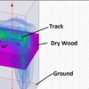
Finite element modeling puts it at about 1.08pF per foot of 3-rail o-gauge track (with some assumptions about height above the floor and table thickness). This is an overestimate by maybe 30% since it counts fringing at the end of the section I made which doesn't happen in a continuous track. FEM is usually about 1-2% accurate to real world. I'm using HFSS 14 for this.

track_sim

Attachments

Images (1)
  • track_sim

If you look at a club like the NJ-HR, I'd bet they have at least 3000 feet of track, so my estimate of .002uf seems a tad low.   A single line around the layout is over 400 feet, and they have tons of sidings and yards, all are contributing to the capacitance.  I suspect that Eliot's layout in development has several thousand feet of track when all is said and done, other large clubs have more than you might imagine as well.

Last edited by gunrunnerjohn
gunrunnerjohn posted:

If you look at a club like the NJ-HR, I'd bet they have at least 3000 feet of track, so my estimate of .002uf seems a tad low.   A single line around the layout is over 400 feet, and they have tons of sidings and yards, all are contributing to the capacitance.  I suspect that Eliot's layout in development has several thousand feet of track when all is said and done, other large clubs have more than you might imagine as well.

We have about 7700 hundred feet of track at the NJHR running off of 6 TIUs.    400ft is a good estimate for our longest run. 

Per all the good information included in this thread, I have been doing some additional DCS signal testing at NJ-Hi railers.  Our 30' X 200' layout (7,500+ feet of track) has had some signal issues and we addressed the TMCC signal issues by cleaning up some of the wiring and adding a TMCC buffer, but DCS still has some issues of loosing control of engines and hard to add an engine to a handheld.  I have taken DCS signal strength readings w & w/o TMCC connected and there are only minor differences in the DCS signal +/- .6vpp, and there seems to be no difference in DCS engine performance.  

A temporary fix for the issue of adding an engine to a DCS handheld (no problem when using the DCS app or when the handheld is tethered to the TIU), I have installed a tether cable from the TIU to the perimeter of the layout so people can connect their handhelds directly to the TIU for adding an engine.   Does anyone know why the "add engine" function seem to be harder to perform than many of the other functions?

John, Adrain if you need any readings/testing from our layout to help you guys out, let me know.

Great work guys,

Bob D

Add Reply

Post
The DCS Forum is sponsored by

OGR Publishing, Inc., 1310 Eastside Centre Ct, Suite 6, Mountain Home, AR 72653
800-980-OGRR (6477)
www.ogaugerr.com

×
×
×
×
Link copied to your clipboard.
×
×