Thanks @G3750 I still got details to add but this is a good start. It's actually an assembly but we'll get to that in later posts.

@Rescued Trains I will. The test layout is 4x8 and I've been moving everything (track and boxes) under than table. Then I'll put plastic over the floor, all the walls, the test layout, etc. The ceiling will be the only uncovered area so I can spray freely. I got my paint respirator ready too. I'm a terrible painter and I've said that before. I just hope that I can get some decent results haha

@Mark Boyce posted:

Bill, they look great!

I don’t know about your field of work, but I worked in mine for 43 years, and I never felt like an expert.

Thank you, thank you. The revisions are in the works.

The best way I can describe my current job: "look out kid, it's something ya did. God knows when but you're doing it again". 39 years, 11 months till retirement though!

I still haven't got it together and painted the ceiling. I bought a sprayer though. I cleaned up some more stuff in the basement and discovered a leaky shower drain. It looks to be the original copper piping from 1962 and while it isn't over the layout, it is in the paint zone and so it will need replaced. Hopefully upgrading from copper pipe to plastic will be easy.

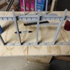
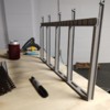
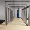
I did go to the store and get myself a piece of plywood to start building a test mill. Pictures attached. What I learned is that I better build a good and level layout if I plan to use a level to get straight columns and I better draw out my grid for placing the foundations. Thank goodness I don't work in construction in real life haha I planned well enough for the structure itself but totally failed to figure out how to place it good and straight. I'm considering building it on the final layout so that the building is built on a piece of wood cut to the size of the building footprint. Then I can just use the edges of the board for alignment. It also is appealing because I can just lift the building off the layout when/if the time comes to move the layout. Plus it would let me do some modelling off the layout in the building which could be very helpful.

It's also got me thinking more about how to get a crane up there. I remember riding the crane down the runway at the foundry and the truss was not more than two feet above my head. It was a lot tighter than I expected. I modeled the crane like that but I'm looking it and wondering if I'm going to be able to fit small motors in the same scale space. We'll see. I'll know more about that soon enough.

I think/hope my filament got damp and that's what caused the weird pores/spots on the columns. I was going to fix that in the final print by using fresh filament and dropping my speed a touch but it kind of looks like peeling paint that you might find on those old columns. Maybe I'll leave it. Obviously, a ton of weather work will need done but I'm mostly testing fitment and appearance. I was surprised at how wobbly it is. Everything from engineering statics class just came back to me today haha

Besides that, I have been running the ingot car around the layout with varying amounts of weights in front of and behind it. It seems to have a weak coupler. But it tracks well and hasn't given me any trouble besides leaving the train behind when it uncouples.

Attachments

Images (5)
  • IMG_20210213_122332004
  • IMG_20210213_122342951
  • IMG_20210213_125322250
  • IMG_20210213_125331263
  • IMG_20210213_125334209

Nope! @Mark Boyce The columns and parts on the bottom are my own design based on a mix of info pulled from drawings, first hand experience, and what would work for assembly. The pieces connecting the columns across the bay are Plastruct. They will be the bottom of the truss when I get around to working out the sizes for the truss.

I'm hoping this structure stiffens up once I add the sides. It should. I might make an appointment at the museum and see if I can dig up a blue print showing the bracing between columns.

Exciting times on the test layout.

The attached videos and pictures show a cast house in the works. Disregard the hot glue please. I like hot glue for checking fit because it doesn't magically find my skin like super glue does and it dries pretty fast. I usually get rid of strings with a blow torch but the cylinder is out of propane.

This experience went much the same as building the start of the open hearth: everything is not straight. I think the solution here is to try to use Plastruct columns instead of printing my own. It would help.

I also realized I failed to print holes into the cast floor for the iron to drop into the torpedo cars below. WHOOPS! I'll have to correct that on the next go around I suppose.

This model comes out 3/8" bigger than what I planned for in the track design but I don't think it will hurt anything. I'm actually much more concerned about the height. The test layout was moved away from the walls to allow for ceiling work to be done so those ducts won't play as much of an issue in the final layout but even still, it sure is close to the ceiling. The blast furnaces will only have the helix under them under the table. I'm considering dropping their elevation a bit. I like the fact that it will add to visual interest (the world isn't flat afterall ) and it will reduce the grade for the high line and that will make the grade look more believable.

I am very pleased with the clearances. B6's, 0-8-0s or the little 0-6-0 docksiders will be working the blast furnaces (torpedo and slag cars). All three clear with just over a scale foot of room.

Hopefully these videos come out ok. They had sideways thumbnails but played upright on my computer.

The rest of the day will be spent rearranging more of the basement and cleaning the ceiling to prep it for paint.

EDIT: Yep. I filmed that with a vertical phone. Sorry! I'm new to the video stuff. I was focusing on trying to hold the phone still. I didn't consider portrait vs landscape

Attachments

Images (2)
  • IMG_20210220_122832037
  • IMG_20210220_122837993
Videos (2)
VID_20210220_122558822
VID_20210220_122650817
Last edited by BillYo414

Bill,

I like your build on  the blast furnace.  Is it 3d printed?

If I may offer a suggestion,  lower the height of the casting house floor to expose more of the hearth. I don't know how much detail you're putting in to the cast house but you have plenty of room above the submarine cars. That way you can detail the iron notch and slag monkeys below the bosch.  Just a thought.

@third rail Yes! It is 3D printed. I plan on finding a way to smooth the surfaces and whatnot. I actually raised the height of the furnace slightly because I'm at the lowest height I can go to fit my biggest switcher under it. There will unfortunately be a small compromise in how high the floor is relative to the hearth because of furnace height, ceiling height, and locomotive height. I won't have a slag monkey. I'll be modelling the method where the slag runner is higher than the iron runner and there's a slag gate to make the slag flow over that way. I know a few furnaces in Youngstown had this style at some point. I mostly went with it because of the way the tracks fell on my design. Of course, that's always subject to change as layout building gets underway and I find out I need to make changes.

@luvindemtrains this is a fictitious mill set along the Mahoning river in a fictitious city but the design of the furnace is based on the Sheet & Tubes Campbell Works furnaces, the Hubbard furnaces, and the Anna furnace in Struthers. Some of the buildings are based on buildings from Valley Mold in Hubbard and basically all the buildings that were along the Mahoning River. So it's a big mix of mills in the Mahoning Valley and I set them up so they'll fit on my available space.

Awesome Bill! I spent 6 years in the Youngstown area and became very interested in its history after I left. You certainly have to study this area if you are interested in how big this industry was in the Midwest and specifically in Ohio. There was a hobby shop in Boardman that used to be in a barn. I believe it has since closed down. The owner allowed me to lay my first set of engines away and pay on it for an entire year. I was a poor college student at the time and I think that was his motivation to pass the hobby on to a young person. The units were a pair of Williams conventional NS Dash 9's, one powered and one unpowered. I still have them but have not run them much. When I finally was able to take them out of the store boy you couldn't tell me anything. I realized several years after purchasing them, that the engines lacked a lot of detail but they will always be special to me and remind me of my time in that area.

Dave

That's cool @luvindemtrains! I can't think of what hobby shop you're talking about. Maybe it was before my time? I only remember Amer's, Boardman Hobby, and Brothers Trains. Boardman Hobby is the last man standing over here that I know of. Austintown Hobby is around but I think they're more RC car focused. That first engine you earn is always a special one, no doubt about it.

I love the history here in the valley. I always was fascinated by the size of the mill buildings left in the 90s when I was a kid but I definitely got into it in the last few years. Fortunately, a lot of the history has found its way onto the internet in the last few years. It's made me realize just how much the area contributed to steel production.

Great story, Dave!!  I sadly do not have the first train I bought.  I ran it a lot through high school and commuting to 2-year technical school.  When I moved to Richmond for work, I pack it all away in my dad's shop, which by then was just storage.  I knew it got hot in there, but when I opened the boxes years later, the plastic had gotten soft and drooped.  I threw it all out.

Bill,

I may have mis-spoke. The hobby shop itself may not have been in the barn but I know you had to ride by a barn to get to the store. I believe this was the new location at the time. It could have very well been Amer's Hobby Shop. I will check my boxes to see if I still have that information. I just know it was off of 224 in Boardman.

Dave

No real exciting progress to report. I have not painted the basement ceiling but I have continued to prep for that. There are two sections of the cinder blocks that stick out of the wall about 3.5" so I'm going around the three walls of the layout putting 2x4s up so I don't have to deal with that. They're attached at the ceiling so I have to get them up before I go ahead and paint the ceiling.

I've been tinkering with how I want to build the table too. I would love to never move again but an unmarried 29 year old can't predict that sort of thing so I decided to build the table in sections that around 4' wide and vary in length. They would be framed with 1x4s. I wanted to use homasote (or an equivalent) so I'm not sure if I would use plywood and a sound deadening material or what for the tabletop. I would like to use terminal strips with labels to run wires around the underside of the layout to make disassembly neater. I'm a little paranoid about having so many connections but I bet I'm overthinking it some. I'll probably just bolt the sections together.

That just leaves the table itself. I suppose it'll be sturdy on its own but I'm considering anchoring it to the walls. I was going to anchor it to the floor but I would rather not make holes in the concrete floor if I could avoid it.

The other problem I have to solve is the part where I have a lower level. A four foot shelf for the top level won't be too hard to support if it's anchored to the wall, I think. But the big tables at the end might be tough to support. One end of the lower level will just have a helix under it so I'm not concerned about supports coming down through the helix. But I was hoping to put a town at the other end to generate extra freight and passenger traffic. That might come down to using something more than a 1x4 to frame that end of the top level of the layout or just deal with the supports through camouflage.

The mill building has been going well. I don't have any pictures to share though. I broke the 3D printer the other week and decided it was a good time to upgrade some parts. It has a new hot end on it now and the quality of the prints are just astounding compared to what I was getting. I wish I would have upgraded a while ago! I changed the design of the columns to give me a slot to push angle iron (L shapes from Plastruct) through so things are aligned better. I also added small nubs to the columns so adding cross braces is easier. It's about time to place my order for corrugated siding too so the building is more rigid for the crane. I'm heading to the machine shop this week to get a quote on getting parts made of steel so the cranes don't bounce of the track so easily.

So that's the news. Not too exciting this time. I guess this is the unglamorous portion of model railroading! I expect progress to really slow down with the weather getting warmer. There is a lot of work I need to do outside on my fixer upper house so it looks like it belongs in the neighborhood haha but I think that printing of the buildings will continue because I can send the command to the printer and go do some landscaping and trim painting. I will post some pictures of the building when it's standing tall and hopefully has a crane in it.

Bill, I would suggest you purchase Jim Barrett’s recent book. It’s really helpful. He mentions using breakaway connections which would help with dismantling; should it become necessary. Since you are still contemplating the process: have you given consideration to adding more lighting (with dimmer switches) and additional outlets? Also, make sure your HVAC is adequate for the area. This is the process that I’m almost done with so the information is fresh.

@Tranquil Hollow RR I will look into the book! I know I'll need to add some lighting but I had not considered dimmers. I could look into it. But I do intend to run some extra outlets in the ceiling. It shouldn't be too hard as there are already two outlets up there. HVAC should be covered. It's not ran the way I figure is correct but it does keep the basement more comfortable in the winter time!

@Mark Boyce I will look these up. I thought terminal strips would be secure at the expense of convenience but I'm totally open to something better.

I constructed my train table over a number of expansions. It sits on the floor, with different sections bolted together and is quite sturdy. I used 2x4 for the legs, with 1x2 connecting the legs at both the top and bottom. This made things quite stiff, and easy to move without bending or damage during assembly. The table top is 3/8 plywood, with carpet underpad on top to deaden the sound. A layer of blue or pink foam is used in some locations. The advantage to the foam is you can carve ditches and streams in it, giving the illusion of a varied landscape, even though it is really quite flat and level.

@Joe K Would you say it's sturdy enough to crawl on? I never heard of using carpet padding to kill sound. That's a pretty good idea! I have heard of using the foam insulation boards and that's still an option because of the opportunity to add ditches and whatnot to the layout. It prevents it from being so flat and that very much mimics the region I'm modelling. I know homasote is pricey so foam is definitely an option. 

The strength of the table will be based on the amount of cross bracing you use, and the distance between the legs. My legs are about 30" to 36" spacing. I connect my leg structure with cross braces both above and below the 2x4 legs (this creates a rectangle), then have cross bracing, again at the top and bottom of the legs connecting the leg "rectangles" together. You can use 1x3 for this at the back, and 1x2s at the top and bottom. Based on your table height, you may need to have some "X" cross bracing to keep things from moving side to side. My layout utilises the corner walls to prevent side movement of the table. The table is not attached to the walls, however the walls give it stiffness support.

I covered my layout in carpet underpad, then painted the underpad with brown "earth coloured paint" mixed 50-50 with water to allow more time to dry.  (painting carpet underpad may suck the water out of the paint before the paint cures and dries, so I use a watery paint mixture to provide extra drying time.) While still wet, I sprinkle on grass texture (coloured sawdust) and some N-scale ballast to provide a basic ground appearance. After the paint dries, you brush off the excess ground cover and re-use it. You can then add more layers  later, after the track is in place. This gives the layout a good look quickly. With the carpet underpad, you can run wires between the table top and underpad, then poke it through under the track, operating accessory or building as needed. If you decide to change the location of a building or track, you just move the wire. The underpad naturally "seals" the cut needed for the wire.

My layout signal system uses lots of phone wire for occupancy detection, so all these wires run under the underpad, and I just poke them through at the track connection point. This eliminates the need to have small wire holes in the tabletop "all over the place".

You can easily stand or kneel on the underpad, as it was almost designed to withstand the weight of a person. If you use foam, you have to be a little more careful of standing on top of it as it can be indented by your weight. The advantage of the carpet underpad, is I can move things around easily, so as a result, my layout went up quickly, and I have moved track and buildings all over the place. After every York trip, I learn more, buy more and stuff gets moved.

Add Reply

Post
The Track Planning and Layout Design Forum is sponsored by

AN OGR FORUM CHARTER SPONSOR

OGR Publishing, Inc., 1310 Eastside Centre Ct, Suite 6, Mountain Home, AR 72653
800-980-OGRR (6477)
www.ogaugerr.com

×
×
×
×
Link copied to your clipboard.
×
×