
For those old-timers like me, you may recall that in the early days of this forum discussions of voltage spikes were quite common. This was probably due to the fact that our trains were being made with more and more electronic features. I don't read much about voltage spikes anymore, and am not sure why that is.

I recently had a collision on my layout resulting in some derailments. One of the engines involved developed a problem and wouldn't run. Fortunately, it was under warranty and was repaired. This got me thinking about voltage spikes. FWIW: I can't be sure it was the collision that caused the damage, but it seems logical.

I recall reading in the early DCS days that the TIU contained voltage spike protection - but that the circuit would eventually lose its efficacy over time. Am not sure if my memory is accurate for either one of the above statements. I am running both DCS and Legacy and thus all power is routed through my TIU's and my TIU's are quite old.

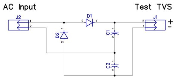
I remembered having something from those early days and dug around my workshop and found a little bag of Mouser ESD suppressors ~ part #625-1 5KE33CA - these are transient voltage spike suppressor diodes. Then, I remembered making a voltage suppressor using these diodes on my last layout - its really easy, just bend the ends 90 degress and insert in banana plugs of transformer.

Long story short, I made four of them for Z-4000 transformer outlets as a stop-gap measure until I learn more.

Has anyone kept up on voltage spikes and whether this is still a problem? Am not sure if more recent trains are more robust electronically speaking then the ones from the late 90s and early 2000's?


Original Post

Replies sorted oldest to newest

John and everyone,

Are you using anything special to protect your trains?

I last bought the bag of diodes from Mouser in 2000 , however I think I found the right part: https://www.mouser.com/Product...jLZ6j4EQ5nBpTQ%3D%3D

Using the part # I found this on digikeys site: https://www.digikey.com/produc...179ee36dbba38034f216

Given that the voltage protection circuits in the TIU don't last and neither do the add-on diodes and that manufacturer's warranties are only a year, I think this is a good idea. Are the ones above good ones to use or what do you recommend? If I find them, I guess I'll replace them annually like suggested above.


Jon1443 posted:

Are TVS diodes necessary if you're still running all postwar, and nothing "modern"?

Nope. Some modern components are sensitive little buggers. Especially memory oriented chips.

Post war is more robust electro-mechanical for the most part.

That said, after GRJ pointed it out once, TMCC seems pretty robust to me too, but for a few pennies a TVS is additional insurance worth while for command folk imo. I only have two TMCC. I don't use sound, and don't care if the boards die, so have abused them without a hitch.

   MTH's approach early on didn't impress me at all in that way. I think my brother would have saved a whole lot of cash using TVS. A few never made a full loop, dying on the switches.

Ron, others have posted good pictures...and like Ted said they are bidirectional so you don't have to orient them.

Cam, that is a great article - I have to admit it's over my head a bit, and seem to recall reading it years ago. I saved it to my computer just now.

fwiw: I've had a number of trains over the years become expensive doorstops...mostly PS1 stuff, but some PS2 and my latest failure was a Legacy engine, which as I mentioned was under warranty so I am taking precautions as I seem to have derailments and collisions quite often (operator error The transformer circuit breakers always trip but that is not adequate protection for our sensitive trains.

Static shocks can be damaging too as Adriatic pointed out.


I don't know about articles, but the absolute best place for protection diodes is right across the power pickups of individual locomotives.  Obviously, it's also the place that's the biggest PITA to install them!  

In general ESD protection should be close to the circuit you're trying to protect.  If your TVS is at the transformer, when the train is 30 feet away and any circuit is interrupted that has inductance, the spike has to travel all the way to the TVS in order to be suppressed.  The inductance of the entire path between the TVS and locomotive affects the ability of the TVS to effectively suppress the spike.  OTOH, if the TVS is in the locomotive, any incoming transient is first met with the TVS protection diode.

TedW posted:

The TVS diodes used in this application are bi-directional(no band).  Here’s a couple of pics of acceptable diodes and install locations.  At the track connections is also a good location.  Hook up straight across the hot and common terminals.

B71BC81E-1BA2-4568-A0A7-D74965AFD51E7199DEC8-36CF-4855-9AE2-A7C799BDB97A

Ted and others,

I noticed in Ted's picture above - the Mouser P/N differs slightly from the diode referenced in the article Cam posted, above...in Ted's pictured is Mouser P/N: 576-1.5KE36CA, where the one referenced in the article that Cam posted is P/N: 576-1.5KE33CA

For a non-electrical engineers like myself, is one preferred over another?

Thanks.

Paul


gunrunnerjohn posted:

I don't know about articles, but the absolute best place for protection diodes is right across the power pickups of individual locomotives.  Obviously, it's also the place that's the biggest PITA to install them!  

In general ESD protection should be close to the circuit you're trying to protect.  If your TVS is at the transformer, when the train is 30 feet away and any circuit is interrupted that has inductance, the spike has to travel all the way to the TVS in order to be suppressed.  The inductance of the entire path between the TVS and locomotive affects the ability of the TVS to effectively suppress the spike.  OTOH, if the TVS is in the locomotive, any incoming transient is first met with the TVS protection diode.

Which begs the question, “Why do the manufacturers not install the TVS diodes in the factory?”

For a few pennies, the company could save themselves a bundle in warranty cost. 

gunrunnerjohn posted:

I don't have any pictures, but they simply go from the center roller connection to frame ground, pretty simple install.

Thanks John.  It does seem easy, but I have some steamers that have multiple pick-up rollers.  You only need to install one diode to one roller, correct?  Also, what about the tender?  If a diode is placed on the engine, would the tender need one as well or is that "overkill"?


Thanks, John.

For you guys thinking of putting them in the engine...keep in mind that you'll likely need to replace the diodes after time, just like those of us who use them at the transformer or track connection. I understand that these diodes can only negate so many voltage spikes before they become in-effective, maybe its just one spike, I have no idea. I also understand MTH places them in the TIU's, but again, after spikes they become in-effective.

Last edited by Paul Kallus
gunrunnerjohn posted:

...

As far as testing for open, it's a lot more complicated than an ohmmeter.  You need a current limited variable voltage supply to test the breakdown voltage of the TVS to see if it's still meeting it's specs. 

So what is the thinking on preventative-maintenance or testing a TVS?   

I think you could count on one hand the number of OGR'ers with a current-limited power supply that goes up to ~40V.

Soooo.  I was thinking maybe a 25 cent capacitive voltage-doubler circuit that would convert 18V AC that presumably every O gauge user has to higher voltage DC...then use any DC voltmeter with and without the TVS to see if the DC output clamps to ~33V, ~36V, or whatever.  The key point is the low-cost of this "tool".  If there is interest I can elaborate.

Or, to Paul's point, maybe everyone replaces all the TVS diodes (good or bad) on their layout at the same time they change batteries on their smoke detectors? 


Last edited by stan2004

I have an HP 50V P/S with current limiting, so I could do a simple test.  OTOH, since you have to remove the TVS to test it, why not just replace it with a new one, they're cheap.  Why waste the time testing it?  Another point, they most often fail shorted.  Here's one of many references, this one in a Microsemi "MicroNote" about TVS devices.  In that case, it's easy to determine as you have a short circuit.

In the vast majority of cases, a TVS will fail in a shorted or severely degraded mode when overstressed.
This has often been the preferred failure mode for many applications, since the device would then
protect the remaining sensitive circuit from further severe transient threats due to its “electrically
shorted” shunt path to ground in front of the protected load until the device is replaced.

gunrunnerjohn posted:

I have an HP 50V P/S with current limiting, so I could do a simple test.  OTOH, since you have to remove the TVS to test it, why not just replace it with a new one, they're cheap.  Why waste the time testing it?  Another point, they most often fail shorted.  Here's one of many references, this one in a Microsemi "MicroNote" about TVS devices.  In that case, it's easy to determine as you have a short circuit.

In the vast majority of cases, a TVS will fail in a shorted or severely degraded mode when overstressed.
This has often been the preferred failure mode for many applications, since the device would then
protect the remaining sensitive circuit from further severe transient threats due to its “electrically
shorted” shunt path to ground in front of the protected load until the device is replaced.

Sure.  But what does severely degraded mode mean?  In the DCS-TIU signal degradation fiasco, IIRC the DCS signal level would slowly degrade over a period of months...presumably from repeated "strikes" of transients due to the harsh/severe operating conditions of the club layout.  Weren't there TVS protection in place that failed in the "open" condition or some "severely degraded mode"?

In any case, I'm thinking that anyone who takes it upon themselves to routinely replace the albeit "cheap" TVS protectors would find it interesting to see what the deal is...in the spirit of "inquiring minds want to know." 

Last edited by stan2004
rtr12 posted:

Stan, I am always interested in your (and GRJ's) ideas, projects, etc. so I would be one that would like to hear more about TVS testing. I have a current limited DC power supply (from a kit), but as you point out I don't think it goes up to 40 volts (or even over 33?).

Yup.  Without getting into the tedious nitty-gritty you run into certification limits (e.g., UL, CSA, etc.) when voltages reach 40V or so.  Let's get to the fun stuff.  So here's my 25 cent TVS "tester".

macgyver clamp tester

I figure everyone on OGR has at least 18V AC.   There are many ways to step-up an AC voltage to the 40V or so needed to mess with the 33V or 36V TVS clamps which seem to be popular amongst the OGR crowd.  I choose not to comment on the whole TVS concept and simply offer this with a positive pro-active mindset... take it or leave it. 

So with generic components that electrically inclined DIY'ers should already have lying around in their parts stash you can build a so-called voltage-doubler which converts AC to DC.  The capacitor is 0.1uF rated 100V.  The diode is generic - I show a 1N4003 as I suggest this as one that any self-respecting OGR DIY'er should have just because (and if you hunt around you can get them for 1 cent).

With 18V AC input, the voltage-doubler generates a ~40V DC output.  I show a "free with coupon" Harbor Freight DMM simply to show that you don't need some fancy dancy meter!

1) apply 18V AC

2) confirm ~40V DC output

3) place 33V or 36V TVS diode in question across the DC output of the voltage-doubler.  In above video I show a 30V and 22V clamp diode; I don't have the 33V or 36V TVS that everyone talks about.  If the TVS is failed in the "open" mode then the DC voltage will not change (stays at 40V or whatever).  If the TVS is failed in the "shorted" mode then the DC voltage measurement will drop to 0 V.

Note that there are many variations of AC-to-DC "doubler" or "multiplier" circuits.  I am suggesting this one because it will NOT draw excessive current if you place a failed-shorted TVS across the output.  That is, there are some versions of AC-to-DC multipliers that can draw Amps of current which would be untoward and annoying and probably burn your fingers.  For the technically curious, the "trick" here is to leverage the impedance of the 0.1uF capacitor to limit current.  That is, a 0.1uF capacitor at 60 Hz "looks like" a 25K Ohm resistor which is a good current limiter.


Attachments

Images (1)
  • macgyver clamp tester
Last edited by stan2004

Thanks Stan! Earlier I tried a sample circuit from a book I have and got 52 volts from the Lionel 18 volt accessory transformer on the bench. It used 100uf caps and mine were only 50 volt so I quit after seeing the higher voltage to be safe. Must have been one of the 'variations' you mentioned above and more than a doubler.  

I like your setup much better and will give it a try tomorrow. I think I have all the parts needed for it and I think the 0.1uf caps I have are like 1000 volt or something really high like that. I might even try a small PCB or something? Maybe like a battery tester or something where you just touch the TVS leads to some contacts on the PCB. Thanks again!

Last edited by rtr12

Yeah, I figured you'd get a chuckle with that.  Of course it's from that MP3 you posted for your O-gauge Wiener-mobile that you inspired me to do.  Now I know you actually watched the video! 

To each his own, but I figure some guys would be curious to know if the TVS is functional upon replacement.  Again, we're talking 25 cents!  As you may recall, my offer still stands:  at any time of your choosing I will send you a quarter for free as long as you pay shipping!

Last edited by stan2004

I had to start the video twice, I thought I was hearing things!

I'd probably be more curious if the new TVS was functional.   If I took an old one out because I thought it was bad, it hits the can.  I'll have to hook one to my HP supply and do a little test.

I'm suitably impressed.  My 36V TVS limited right at 36 volts at around 50ma.  I guess that one is a good one.

rtr12 posted:

Thanks Stan! Earlier I tried a sample circuit from a book I have and got 52 volts from the Lionel 18 volt accessory transformer on the bench. It used 100uf caps and mine were only 50 volt so I quit after seeing the higher voltage to be safe. Must have been one of the 'variations' you mentioned above and more than a doubler.  

I like your setup much better and will give it a try tomorrow. I think I have all the parts needed for it and I think the 0.1uf caps I have are like 1000 volt or something really high like that. I might even try a small PCB or something? Maybe like a battery tester or something where you just touch the TVS leads to some contacts on the PCB. Thanks again!

Not sure which "topology" you tried but all these doubler/multiplier circuits respond to the peak or maximum voltage.  So for an 18V AC pure sine voltage from a train transformer, the peak voltage is square-root of 2 times the RMS voltage or 18 x 1.4 = 25V.  So if it's a doubler, then you get 50V.  Compared to a 0.1uF cap as I suggest, your 100uF cap "looks like" a resistor that is 1000 times smaller hence smaller voltage loss in the conversion.  It gets arcane and boring really quickly!

I know you've been learning about PCB layout and this would/could be a small board that would be maybe $1 all-in (raw board plus components for a buck).  I figure you could place some square pads/islands (no soldermask) on the board where you'd touch the 2 terminals of the TVS to the board.  In all seriousness, it would be fascinating to hear from a cross-section of OGR readers as to the "status" of their TVS clamps.

Last edited by stan2004
gunrunnerjohn posted:

Remember, a large 1500W TVS has significant capacitance, so if you use too many, it will start to affect DCS performance.

Interesting comment John!  I remember about 2 or 3 years ago when TVS usage was generating a lot of usage comments here.  One that was mentioned fairly often was this one: (loosely quoting) "I put one on every track connection (e.g. lockon)".  So since I typically have 15 or more because of isolating tracks sections due to DCS performance recommendations, I bought 25 and put one on every lockon.

I also remember that DCS users were saying they even put one on each TIU output post and also for those that use star wiring, they put one on each terminal strip.  So I do both of those too.

But your comment now says to me that I shouldn't be doing that.  Am I interpretting correctly?

As always, thanks - walt

Stan, This is the one I tried first. 

Voltage Doubler 1 [Large)

Yours works much better though, so I went with it. Worked great on the breadboard, just like in your video (and it also works just as well without the Oscar Meyer weiner tune).   I like the idea of the pads too, which I just figured out how to do in Diptrace.

Although the Lionel Accessory transformer has a pretty substantial range of dial adjustment, it doesn't have much fine adjustment, it's like from 0 to 13-15 volts right away in the first 1/4 to 1/3 of the dial. You can do a bit better if you fiddle with it, but that's a pain too. Coarse adjustment is basically on or off. 

I made a PCB for it also, it was $3.90 for 3 PCBs shipped at OSHPark, I ordered 3. It could probably be reduced in size a bit, maybe leave out the corner mounting holes? It started out at like $4.25 fr 3 and I shrunk it nearly an inch each which only got it down to $3.90. Not sure how much savings further shrinkage would produce? Of course, if GRJ got a hold of it he could probably get it down to $1 or so for 3.

I haven't tested the PCBs, but will as soon as they arrive. I'll post the files for them if it all works. Or if anyone want them now I can do that too, but I would hate to give anyone something that didn't work properly.

Here's JPEGs of what I have so far:

Voltage Doubler v1

Voltage Doubler PCB v1

Voltage Doubler 3D v1

I couldn't get a large pic of the PCB, so I enlarged it (schematic too, but it came out better). Reason for the poor quality. I'll have to do some more self education work on that part. Bigger drawings work better... 

Attachments

Images (4)
  • Voltage Doubler v1
  • Voltage Doubler PCB v1
  • Voltage Doubler 3D v1
  • Voltage Doubler 1 (Large)
Last edited by rtr12

Ask and you shall receive.   I couldn't hit the dollar figure, how about three boards for 65 cents?  Total time to deliver, about 20 minutes.

I figured some test leads for the test output would be useful instead of the test pads.  After all, you need to connect the voltmeter and the TVS under test.

Attachments

Images (4)
  • mceclip0
  • mceclip1
  • mceclip2
  • mceclip3
Last edited by gunrunnerjohn

Hey, that's not fair, you used SMD parts! I am not done stocking up on the through hole parts yet and now I need SMT parts. I do have to agree that one is pretty small and for 65 cents you sure can't go wrong.  I was pretty sure you could shrink things down a bit there.

Well, I do have that microscope thingie around here somewhere...and Stan was also suggesting a couple SMT chips on the CA-CC traffic signal PCBs which I still need to order and test out. Maybe it's time to give that microscopic stuff a try. 

Hmmm...I thought I routed the traces, but I always usually miss or goof up something somewhere. I better go check while there's time to correct the order... Thanks!

How do you get the green 3D boards, mine always come out brown like the one above. I won't go into the missing patterns I have to battle every time I try that...

Last edited by rtr12

I probably would have trouble getting a thru-hole design down to less than $1 for three.  OTOH, with an SMT design, I could have gone even smaller, just put a couple of the parts on the other side!

If the preview is what you sent, there's no traces.  Hard to believe all the traces are on the bottom, but maybe they're the same color as the solder mask and/or board and they're invisible?

Truthfully, I don't know how you got the brown boards.   OK, got it.  In the 3D preview, look in the upper right hand corner, you pick the colors of everything there.


Attachments

Images (2)
  • mceclip0
  • mceclip1

BTW, don't feel bad, I did that once as well.  Only I didn't see it until later, and I realized looking at the order when I was wondering when it would ship then I noticed I couldn't see any traces!  I went back to the Gerber files and could see I didn't route it.   I just dropped those boards directly in the trash.

Last edited by gunrunnerjohn

Now that you pointed it out, I see the colors. Guess I have seen that before, but it never occurred to me to see what that did. 

Yes, all I saw was ratlines when I opened the file. Not sure how I managed that, but I almost always goof up something. Haven't had a 'perfect' one yet, but got pretty close. 

OSHPark didn't give me any errors either? They have on previous PCBs, but I forget what the errors were? Guess they don't check for that? I'll have to be more careful with that from now on. I like doing that too, I like watching Diptrace route all the lines all by itself!  

Anyway, thanks to a keen eye checking on things, all is well now!

Weird they don't check for that one? Seems like they should. Guess they leave that one to the folks struggling to design the PCBs. 

I need to start using the verification more, I don't always do that. Obviously I didn't do it this time! 

I also have a few PCBs that were less than ideal when they arrived. I was able to use them, but some of the components did not fit well with the others, too close. Had to do some whittling on some of the terminal blocks too.   

I had a number that had tight or "no way" fit early on, that's just getting used to dealing with the spacing.   It gets more tricky when the boards get more dense and they don't have 3D models for you to visualize your design first.  I had several throw-aways that parts simply didn't fit.  I'd build one and sky-wire it to test function, and then correct the issue.  It's also why I like to get only a sample of the boards first before I go to press with any number.  I did one board order of 40 boards that had a mistake that I couldn't work around, OOPS!

One trick is to print the preview at 100% size and then lay components on it to see if they fit.

Last edited by gunrunnerjohn
rtr12 posted:

….

The good thing about ordering from OSHPark on weekends is the order, I think, waits until Monday for processing so you have some time to fix your errors. 

Is it still the weekend?  The 2 square pads are obviously for momentarily touching the TVS to the board.  But the meter must also measure that voltage between the 2 pads.  I had imagined using alligator clip cables cut in half for the input and output.  The 4 flying-lead ends gets soldered to the board, 2 inputs, 2 outputs.  The 2 inputs clip to the transformer.  The 2 outputs clip to the meter (set to DC Voltage measurement). 

alligator clip jumper cables 10 for 2 bucks

And, if those mounting holes are large enough, you could run/loop the jumper cable wiring thru them for strain relief.

Attachments

Images (1)
  • alligator clip jumper cables 10 for 2 bucks
Last edited by stan2004

GRJ, that is a good trick about the print out, I'll have to remember that one for future use. So far I have only gotten small quantities either 3 from OSHPark or 5 from JLCPCB. Only thing I have ordered larger quantities of are the TIU Tester PCBs, which I have probably 18 or so left, with parts to go with them. Orders have dropped off lately.

Stan, I was also thinking about something to read the voltage output. By still the weekend, does that mean I need to change something else? I have some of the inexpensive DC digital meters I was using on a few cheap AC/DC converters for the output reading. I also have a few sacrificial alligator clips I got for trial on the TIU Testers, but never used. So I am all set to try all this out. 

I have some cheap left over 2-hole screw terminals or the 2.54mm (Arduino type pins) for the inputs and big pads for the outputs. I think the pads are large enough to accomodate the alligator clip wires and then some, even the clips themselves, they are 2.5mm x 4mm. But, I am open to any and all further suggestions, or corrections if my thinking is way off here. I think I can still cancel and re-order if need be. I don't mind getting a second batch either if necessary. All part of the fun and learning.

And, courtesy of GRJ, we will now have electrical connections for all the components on the PCBs too! 

The mounting holes are 3mm inside diameter, actually slightly over that, 3.125mm maybe. That was another mistake I made earlier, holes way too small for anything but the tiniest of screws. Of course if we use the GRJ downsized version the mounting holes go away, but he has the holes for soldering or installing pins or something of that nature. That 65 cents is tempting! That would be 18 PCBs for the price of 3 of mine, if I calculated that correctly.

I guess it depends on what you're trying to do.  If this is a one-off for yourself, that's one thing.  But speaking on behalf of a hypothetical OGR user, I'd think wires with 4 alligator clips (2 to 18VAC transformer, 2 to meter) would make it easier to use.  Then you just press the TVS in question to the square pads on the board and read the meter to see if the TVS is still alive.  So by it's still the weekend, this would mean adding a couple of pads on the output to solder the meter wires to.

I'm pretty sure that DCS-TIU port tester had a strain-relief hole for the wires to to clip to the TIU output.  I don't know how big those holes were but the idea of course is to wrap a pair of wires thru a single hole.

I don't think you need mounting holes at all, but if you want them, then a #4 screw clearance hole which is about 1/8" should be fine.  You'll have to look up your hole diameter choices minding the plated hole dimension is slightly smaller than the drilled hole dimension (before plating).  Most PCB layout programs allow you to specify plated or non-plated holes but I'm not familiar with your specific program.

As stated earlier, I'd be fascinated to get some field data on whether or not actual 33V or 36V TVS components are failing "open".  If not, then why bother replacing them!  But I suspect most guys would want a completed tester with wires and alligator clips.  Frankly, I'd be pleasantly surprised if someone else pops up, buys the components, raw board, and assembles one of these.  I'd like to proven wrong!


DipTrace allows you to specify mounting holes that are not plated, it's a standard feature.

FWIW, my little board was just a demo to show you what is possible, and that wasn't even the full "shrink" that you can do.  Even using fairly large SMT components, you can make boards much smaller as you can put the components on both sides and you don't have the thru-hole clearances on both sides.  Though I used 0603 sized components, you can larger sizes for easier handling and soldering.  1210 resistors are a good choice as they are 1/4W, a popular power rating for many projects.

Another bonus is many SMT parts are actually cheaper than the thru-hole counterparts.

rtr12 posted:

GRJ, that is a good trick about the print out, I'll have to remember that one for future use. So far I have only gotten small quantities either 3 from OSHPark or 5 from JLCPCB. Only thing I have ordered larger quantities of are the TIU Tester PCBs, which I have probably 18 or so left, with parts to go with them. Orders have dropped off lately.

Rtr, I would be interested in the TIU tester board. Could you share some details please and pricing?

Thanks, Rod

Stan, I'm on the case! I'll make some revisions and see what we can come up with for everything suggested. I'll repost the revised results here in a bit. I like the idea about the alligator clips and I see what you are talking about now. I was thinking along those lines too (where to hook the meter for ease of use), just hadn't put it all together yet. There are holes in the TIU Tester for the wires, they are 2.54mm I think and there are 2 of them. I only used one for both wires on my TIU tester so that might be a good size for the hole. 

GRJ, I used the Diptrace selection for 'mounting holes' on the above PCB, at least I think that's the one you are pointing out of here. I do plan on trying the SMT parts and the 1210 size sounds like a good starting point for a greenhorn! I think I can do that, but I'll have to look into using both sides of the board, I don't know how to do that yet. I have fiddled with the 'layers' a little though. I am guessing that is key to placing things on the bottom. I have noticed the low pricing on the SMT components too, some are really low! 

Rod, the TIU Testers are $17 shipped for one complete kit. The kit and PCB are all through hole components, not too difficult to assemble. They are of the final design GRJ posted in the TIU Tester thread (in case you haven't seen it). There are also some instructions compiled from some of the posts in the thread. If you would like one, email me and I will send you the complete details on ordering. My email is in my OGR profile.

Tom, using both sides of the board is as simple as just selecting the other side in the upper drop-down.  Select the bottom, and you're working on the other side.

Similarly, if you want to move components to the back, just right click on the component and select "Change Side", the component will magically be on the other side.  If you have a lot of components to move, hold Ctrl while you select them all and you can move them all to the other side in one operation.

The autorouter will add any necessary via's as needed to connect everything when you route the board.

Attachments

Images (2)
  • mceclip0
  • mceclip1

Stan, it's still the weekend and I got some changes made. Comments, corrections, scrap and start over, comments welcome and also wanted. Actually, OSHPark has a 'Pause Order' feature, which I took advantage of earlier (they must have anticipated my use of their order system ). I think the paused order can also still be cancelled at any time. 

Voltage Doubler Schem v2Voltage Doubler PCB v2Voltage Doubler 3D v2

It's still the same size. Per GRJ's assistance above, trying the SMT components and making a smaller PCB is next on the list. 

We will see how the SMT experiment goes for final size. Then once a prototype is approved and working, I would be in for offering these as kits and possibly even assembling a few if there is any interest.   

Attachments

Images (3)
  • Voltage Doubler Schem v2
  • Voltage Doubler PCB v2
  • Voltage Doubler 3D v2

Yup. That's what I meant.  As I see it, if the primary objective is to learn more about PCB layout, I'd cancel the thru-hole board order and focus on the SMD version...which, if I understand GRJ's example, gets it down to less than $1 for 3-boards shipped?  Wow.   

All I hear are crickets chirping in regards to anyone interested in buying this "tool"!   The design is simple enough that it's easier to solder it together with whatever components, connectors, whatever a DIY'er has lying around and off you go.  As to assembling/selling this, I think the OGR crowd is better served with more complex designs   In other words, something like the DCS port tester which is a unique circuit and tedious and impractical to assemble without a PCB. 

It is curious that this TVS "tester" and the DCS port tester are cousins in that they relate to the voltage spikes.  This reminds of yet another widget I hand-built also simple enough as to not require a PCB.  There have been several threads about it but the video is the most fun.

Again, component cost is 25 cents or so.  One red LED flashes when a positive voltage spike is detected on the track, the other red LED flashes when a negative voltage spike is detected.  Green LED shows power on the track.  On my to do list has been to integrate this function with a 75 cent electronic "tally counter".   This would count the number of spikes.  The missing link is to economically simulate a button press on the tally counter whenever the voltage spike detector is triggered.

voltage spike counter work in progress

So here's a case where a PCB would be useful not so much because the circuit is complex but because you'd probably want a handful of these scattered around the layout rather than a one-off tool.  Then, after an operating session it sure would be interesting to see if the voltage spikes on the layout are more frequent in certain locations, or near/follow the engine if dragged around on a powered truck as shown.

Attachments

Images (1)
  • voltage spike counter work in progress
Last edited by stan2004

I wasn't happy with the big open space in the upper left corner so I put the strain relief hole there. I can arrange things better than Diptrace, but my arrangement skills still need work. Diptrace is worse, but it's really good at routing the traces, that is if you remember to tell it to do that! The strain relief holes are 2.54mm, That is what the TIU Tester holes were as near as I could read the ruler. 

I'm still on the SMT case as well! Here is my first attempt at SMT PCBs. You guys have finally put me over the SMT edge.   I am not down to GRJ size yet, but this gets it down to $2.60 for 3 PCBs shipped from OSHPark. It uses the 12 size/number SMT components (gotta start somewhere) so the design can still be refined down some. I am still going to try GRJ's suggestion of putting stuff on the back side too, so that will likely reduce the size some. I am not sure how close I can get to the edges and a few other things like that with spacing. At least this gets rid of the big open space in the upper left corner. 

I could have had this done sooner, but I got into a battle with Diptrace over 'pads covering the silk' or something like that. I finally beat Diptrace into submission and won the battle by figuring out how the pad things worked. At least enough to get rid of the errors anyway. I am sure it has brutal revenge planned for me in some other section and is just waiting for me to innocently enter into that area so it can pounce.  

Voltage Doubler SMT PCB v2

I know very little about the SMT components, other than I can barely see some of them. My reason for starting out with the larger size, not sure that is called 12, but parts started with that number and were large enough to see.   I have a couple of GRJ designed PCBs here for TIU protection and I can only see one of the five parts that are supposed to be soldered to the PCB. He told me they have them even smaller than that! 

Don't despair just yet on the TVS tester interest. Things are picking up rapidly, one person wanting one of them already! I don't plan to sell them, I was just going to share the Diptrace files here for anyone interested. But I would also be willing to offer kits at cost, as I do for the TIU Testers. Maybe even assemble a few for folks that can't (or don't want to) do that part themselves. That would make it easier on some folks, may even promote more interest.

I remember that widget you built, I would love to have one of those too. I remember wanting to make one myself at the time. Not sure now why I didn't. Probably lack of knowledge, too many irons in the fire, etc. That is a really neat little module and adding the tally counter would put it over the top! I'm sure you are much more capable than I am, but I would be happy to try and make a PCB for it in Diptrace, if you ever want one. I would think this item would be of interest to many forum members as well. As you say some very interesting information could be gathered with it by using it as you suggest.  

Attachments

Images (1)
  • Voltage Doubler SMT PCB v2

Holy smokes - this thread reminds me of electrical circuits class back in college! Not one of my favorite classes

I ordered a batch of the diodes from Mouser...and figure on replacing them once per year.

One aspect of the protection "location" for the diodes is still unclear to me. A number of you have said that the optimal place for the TVS diodes is in the engine itself. But, to my rudimentary understanding of voltage and amperage, if a voltage/amperage spike occurs, doesn't it have to originate from the transformer (after the derailment or collision of trains on the tracks)? Maybe I am mixing this up with short circuits, i.e., when a train derails or collides with another train? That short circuit causes the voltage/amperage to spike from the transformer, and if has circuit breaker protection the breaker trips and shuts off power (but the damaging "spike" already went out via the terminal posts to the tracks). Thus, a TVS at the terminal posts does the "protection" before the spike reaches the trains on the tracks?

Last edited by Paul Kallus

The best place for transient protection is near the actual device or circuit to be protected.  The spike can be generated by any inductive device, motors, track switches, trackside accessories, or the transformer.  The transformer is not the only device that can generate damaging transients, they can come from many sources.  As we have discovered in some testing done by Adrian, even the chokes we use to improve DCS performance can, under the right circumstances, generate damaging transients.

GRJ,

Here are the Diptrace files for the TVS tester. I'll include them all, through hole and SMT versions, in case you want to fiddle with both.

Everyone else is welcome to these as well, I think they should work ok. But, I have not yet gotten any PCBs made to test out, so they are fully untested as they are now.  

Attachments

Last edited by rtr12

40 cents for the raw PCB.  Maybe 10 cents for the parts.  Now we're talking!

The real conundrum then becomes how to handle the USPS question.  So if you go with the SMT version, you can get the thickness under 1/4" (if you don't ship the cables with alligator clips) and you can use the USPS large envelope rate of just over $1.  Otherwise, you need to use the USPS package rate which starts at about $4 albeit you get tracking 

It always bothers me when you pay more for shipping than the contents.  Yeah, I need to get a grip... 

rtr12 posted:

That is pretty small! I see how you arranged things on the back and I like that better than what I had. I think I'll place an order, can't go wrong for $1.20. And I can still see the SMT parts too!  

It could have been even smaller, but I got to thinking how hard it is to handle something that's only half an inch square.  I actually did that to give you an idea of what you can do by using both sides of the board.  Also, with the SMT parts all lined up like that, hand soldering becomes pretty easy, that was one goal here.

My technique for SMT builds...

  • Place the board in a vice or other clamping method so it won't move.
  • Put a dot of solder on ONE of the pads for the part.
  • Grab the SMT part with tweezers in the proper orientation.
  • Heat the pad you just put solder on and slide the part into place and remove the iron.
  • Sometimes the part is not exactly positioned or sitting off the board.  Press the part in the center with the tip of the tweezers and heat the pad again to flatten it.
  • Solder the other legs/pin/etc. of the part just positioned.

In a more complicated board, you'll also want to think about the order you put parts on, usually I start with small parts and work up the scale.  You can also prep a number of the positions with the solder dot so you can just place a bunch of parts without going back to the solder step.

In truth, for something like this that is intended to be used the way it will be used, I'd probably make it larger and have mounting holes to mount it on a piece of wood or Styrene to allow it to sit flat on the bench while I used it.  It may require three hands to use this tiny board to get the TVS devices.

Last edited by gunrunnerjohn

Stan, I agree on the shipping, it is becoming more than the actual cost of the item being shipped. The postage rates have gone up in the last few months too. I have never tried using the large envelope with less than the 1/4" thickness. I don't think I could get the TIU Testers down to 1/4" thickness or I would try that. I have received one check in a regular envelope that had been half destroyed, required a redo, but so far I have not heard of any of the TIU Tester kits being lost or damaged (keeping fingers crossed). 

Been using Paypal shipping for the TIU Tester kits which has also gone up. They are in a padded envelope and are over 1/4" thick, but only weigh a 2-3 ozs. total. I think Paypal is still slightly less than using USPS directly, but you have to buy labels to print and padded envelopes. If you take it to the PO they will do all the labeling for you. I am not sure if they have one that would work here, but they do have some free envelopes as well, I think. Then there is usually a nice long line to wait in that can take a while. Sometimes you just can't win.  

GRJ, I am still going to try some of the SMT sized PCBs, just for the experience even if I end up using the larger one. AndI will follow your tips above during the 'experience'.  I have been wanting to try some SMT stuff so this is a good and inexpensive starting point. Just wish I would have ordered the SMT parts the other day when I placed a Digikey order...too much thinking all at one time, must have overloaded the mental circuits. 

As Stan points out above, the shipping may be cost prohibitive on the TVS Testers? I know some folks won't want to do this, but it would probably be much less if they ordered their own PCBs from OSHPark with free shipping and then got some components from ebay. Digikey has even raised their shipping costs. As you probably know their first class is now $4.99 and if it's over 14 ozs. it's Priority mail or Fed-Ex, $8.99 for either choice. If you order like a dozen 14 or 16 dip ICs the anti-static tube puts you int a larger box and you automatically got the the $8.99 shipping. Still can't win...unless you have devised a way around this, you are pretty good with all this shipping stuff too.  

You should be able to ship the TVS tester in a First Class envelope with the SMT parts.  What I do is use a piece of corrugated cardboard and cut a hole in the center.  Then I put the item in the hole and put clear tape on both sides.  Another trick to save a little thickness is to specify the .031" thick boards, there's no reason you need 1/16" thick boards for this kind of project.  Obviously, if you solder wires with alligator clips on them to it, they probably will need to be in a padded envelope.

The cardboard is a good idea, and you just use a 'regular' mailing envelope as in for a letter, like I think Stan was talking about. I was wondering about damage with those skimpy envelopes. Thinner PCBs is a good idea too! I'll start saving more cardboard packing materials.

Thanks for the tips, I knew you would have something already figured out on this.  

That sounds encouraging, especially the no problems part. I think I am sold on trying that method, that is, if anyone ever wants another one. 

I haven't had any problems with the TIU Tester kits themselves, but I did get a check that had been partially destroyed for one order. It arrived in a USPS envelope that contained the original envelope (torn up and partially missing) with a note about the letter being damaged. I emailed him about it, then went ahead and sent the kit along with the destroyed check. He sent another check that arrived in one piece the second time. All was well.   

All things considered, I think the USPS really does a good job for the amount mail and packages they handle every day.


gunrunnerjohn posted:

Not less than a dollar for three, but close.

TVS Tester SMT v2.dip


Got my 3 PCBs of this version from OSHPark yesterday and populated them today following GRJ's directions above. Quite tiny I might add, I used the Banggood microscope. It works as intended, just as Stan described in his earlier sample. These are very nifty little tools to have around!  I'd like to try making one of Stan's truck mounted surge detector devices one of these days, as in his video above.

Also, I am now almost certain that I was not put on this Earth to work with SMT components! And these are the larger 1206 size (do they come any larger?).  They even put tiny little orientation lines on the diodes, which I did not see until it was too late...good thing I had 3 PCBs and extra parts.   I think my grandson is in need of some more soldering lessons!

After I realized my mistake, it was an extremely rare moment of frustration. So I moved on to another PCB with the intent of correcting the diode error and salvaging the PCB later. The challenge was to just get one PCB completed with the SMT parts properly attached.  Although it was a bit ugly (well maybe a little more than a bit), PCB 2 was completed and tested successfully! Still struggling, but one down and more to play with. As they say, practice makes perfect.  

If I ever get into anything much smaller I'm going to hire one of those robots that does this stuff for a living. 

Once you develop a technique, it's not that bad to put SMD parts on.  You should be using smaller solder, I use .020" diameter solder for PCB work.

  • Secure the PCB, I use my PanaVise, though there are many methods.
  • Put a dot of solder on one pin, since I'm right handed, that's a pin to the right of the component.
  • Grab the part with the tweezers in your left hand, heat the soldered pin with your right hand, and slide the part into position.
  • Remove the heat and let the solder solidify.
  • At times, the part is sitting up and not firmly against the board.  I just apply gentle pressure with the tweezers tip to the center and heat the solder again and let the part seat.
  • Solder the other pin(s).

Rinse and repeat.

When you get to a more complex board, the order you mount parts starts being significant.  Work from the inside out and do the short components first, then the higher ones.

That is pretty close to what I was doing with the exception of the vise. I'm using mounting putty or sometimes called blue tack, I think, but mine is white. Had it on the microscope base to hold the PCB. It works well at holding the PCB steady, doesn't move at all.

I did experience the part sitting up and not firmly against the PCB thing, Your tip helps here. I sorts did that, but it was a bit of a struggle as the component kept moving around when the solder heated up. I may have had too much solder on the first pad to start with? The 'technique' is still in the development stage! 

I have the Hakko 888D and I was using a Hakko T18-B tip. It is pretty small, but maybe a smaller one would be better? It did seem kind of large compared to the parts. I have a few others and may have one that is slightly smaller, I'll check my stash. Which tip do you use in your Hakko for the SMT stuff?

I was using the 0.020 - 63/37 solder, and it's good quality from Digikey. It's not the cheaper Asian stuff. I have heard most of that stuff doesn't do so well on through-hole or SMT. Watched some youtube vids of folks trying it out, they weren't too happy with it.

Got a couple of emails from OSHPark today, more PCBs are coming. One is the through hole version of the TVS tester and the other is an earlier version of it in SMT form from before you shrunk it down. I'll have even more to practice with soon, probably by the weekend.  

I think I have a tip quite similar to that one, it's slightly different, but has a really small, sharp tip like that one. 

Solder is Quick Chip or something close to that anyway. I have a Digikey order started, I'll see if they have any Kester and give it a try. 

I did another one today and it was a little better, the technique seems to be improving slightly. 

Chip Quick is very low temperature solder for removing stubborn parts, but it's very expensive to use as general solder!  You get a couple ounces for $20, not exactly a bargain.

https://www.digikey.com/produc.../SMDIN100-ND/8681826

Look on Amazon, they have a good price on one pound rolls of Kester 63/37 Rosin Core solder.  It's $23.99 for .031 and $24.95 for the .020, shipped free if you have Prime.

Was just on Digikey, Kester was $55.51 for 1lb of the 0.020. I'll check out Amazon for their Kester solder tomorrow. I really don't need a 1lb. spool.  I forget exactly, but that might be how I ended up with the Chip Quick, it came in smaller sizes?

Hmmm...just took a quick look at Amazon, your prices were for a 1lb. spool, maybe I do need a that much. 


Last edited by rtr12

I just wanted to report on a successful tester build using RTR12's DipTrace files, which he graciously made available. The boards are about $1.20 a piece from OSH Park. I built the thru-hole version using parts in my supply bins. Thanks to Tom; he did all the heavy lifting on this one!

Attached a couple of pix of the tester I just today assembled and tested. Works perfectly, as expected!

I had to drill the strain relief holes out to 9/64” to accept the test lead wires I had on hand. No big deal.

I am glad the board is no smaller than it is; it might get lost in the parts box otherwise! Haha.

IMG_2036IMG_2037IMG_2038

Thanks Tom and the other contributors to this topic; and Stan for the original idea and circuit.

Rod

Attachments

Images (3)
  • IMG_2036
  • IMG_2037
  • IMG_2038

I took a look at this project again and did a minor Tweak of Tom's latest design   I shrunk it so the boards are cheaper, and I also changed the contact point to test points for leads, I think I'd want to clip the TVS and then fire up the tester.  Obviously, DUT is the Device Under Test.  The Gerber files are attached below.

TVS Tester V1.1 Gerber.zip

A thought occurs to me when looking at this as well.  In order to truly test a bi-polar device, you have to swap it's polarity and run the test twice to test it completely.

Attachments

Images (2)
  • mceclip0
  • mceclip1
Files (1)

I like that one!  I made a later version, a bit larger with bigger pads for the TVS leads.. But I think I like the idea of clips for the TVS, no lead bending to try and hit the pads or having to hold them on the pads.

I may have to order some of those and give them a try with all clips. Or wait, I have some extras, I guess I could just solder some clips to the pads...  Also, I hadn't thought of testing them both ways, that's a very good suggestion. Especially for us greenhorns (well me anyway)!  

This is probably a good place to add a photo of a TVS installed in an MTH PS3 SW1500. The two gray wire nuts form junctions between incoming power from the roller-pickups (hot) and truck-frames (ground) and the power leads to the PS3 circuit board. Easy to stick a TVS right there:

         IMG_4182

         IMG_4183

I suspect this is SOP wiring in PS3 diesels in which case it's a simple solution for lots of people. 

Attachments

Images (2)
  • IMG_4182
  • IMG_4183

Add Reply

Post

OGR Publishing, Inc., 1310 Eastside Centre Ct, Suite 6, Mountain Home, AR 72653
800-980-OGRR (6477)
www.ogaugerr.com

×
×
×
×
Link copied to your clipboard.
×
×