cjack posted:

Anybody remember the Raytheon CK722 Germanium transistor...?

My very first transistor, I bought one mail-order, as I recall it was pretty expensive, something like $6-7, a kings ransom in the 1950's!  I was super careful with that part and built a few different circuits all the while following all the handling precautions.  I finally broke a lead off right at the base and killed it, but by then more transistors were available at lower prices.

The first transistors I had were similar to GE 2N107.  I now have two GE 2N107 and three Raytheon CK722 transistors in my collection.  They come up on eBay occasionally.  The blue CK722s are highly sought after.

I started with tube circuits.  I built a Geiger counter using the Raytheon CK1026 Geiger-Muller tube, and a capacity operated relay using the Miller 695 coil.  The CK1026 tubes are very hard to find.  The 695 coils are near impossible.  I've got several of each in my tube collection.  Thank you eBay.

My first job out of college was with Raytheon, new CK series parts were still being released.

Alan Mancus posted:

Ah yes RCA Nuvistors, those tiny tubes in a tin can!

yes I remember them they were used in the tv tuner when there was a mechanical tuner for television! that sure brings back memories!

Alan

Tektronix used them in the input of the 454 oscilloscope. They drifted for about a half hour causing me to have to chase the DC vertical position of the trace. The 454A used fets and was much more stable.

penn station posted:

The relay board in Clem's picture is very neatly laid out.  The power flows from bottom to top with four similar circuits.  A close up of the relays in each of the three rows and a shot of the back would probably be sufficient to work out the circuit.  My first question is what to the toggle switches do?

Toggles turn the system off

clem k posted:
penn station posted:

The relay board in Clem's picture is very neatly laid out.  The power flows from bottom to top with four similar circuits.  A close up of the relays in each of the three rows and a shot of the back would probably be sufficient to work out the circuit.  My first question is what to the toggle switches do?

Toggles turn the system off

There are 4 switches at the bottom of photo.

So to be clear, does each switch turn off (i.e., force OFF) 1 of the 4 blocks irrespective of the shutdown feature of your system?

And those are the ONLY switch/configuration controls to your "Safety Relay" system?

We're trying to help the OP here!  In absence of diagrams/schematics/parts-lists from your custom built system since the OP wants what you have, I think we can get there if you let us know exactly what your system does.  In my opinion that is...


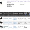
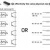
Just about any AC-input optocoupler will work.  I just checked on eBay and for about $1 (free shipping from Asia), you can get 5 single-channel PS2505-1 optocouplers.  You'd use 4 of them.  Note that these devices come in 1, 2, and 4 channel packages and can be "stacked" so that 4 1-channel devices looks like 1 4-channel if that makes sense.

ps2505-x

The PS2505-1, PS2505-2, and PS2505-4 are shown above from DigiKey though minimum shipping from DigiKey is over $4 these days.
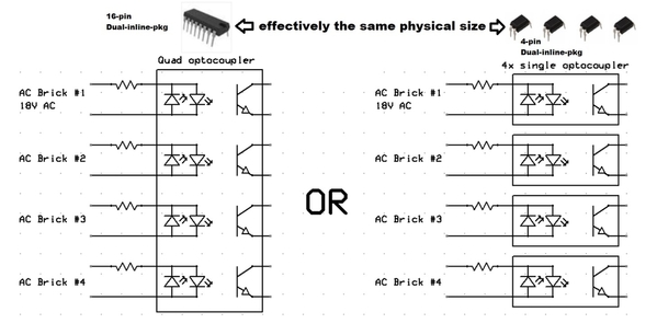
quad opto or 4x single opto

As I type this out, I now recall and dug up a previous discussion about AC-input optocouplers:

https://ogrforum.ogaugerr.com/...89#69285198810032689

So I see there I recommended if only going to "stock" one optocoupler type in your DIY parts stash, use the AC-input LTV-8141.  This part would work too.  And it too comes in 1, 2, and 4 channel versions though their numbering scheme is LTV-8141, LTV-8241, and LTV-8441 respectively.

--------------

But as I stated earlier, you have to be a determined DIY'er.  Some comments that may help or confuse depending on your comfort zone.  I measured the input trigger current to the 4-channel relay module.  Each trigger measured about 1 mA with 12V applied.  So it takes 4 mA to trigger all 4 relays.

Each optocoupler is essentially acting as a bridge rectifier to convert AC to DC.  Drive each optocoupler at, say, 10 mA.  In other words an input resistor of 1K-5K.  You need a capacitor to smooth the full-wave rectified output otherwise the relays might chatter/buzz at the line frequency.  Something like 1uF - 10uF should work. 

If someone/anyone is actually contemplating wiring one up I can peel additional layers of the onion; it may bring tears to your eyes .


Attachments

Images (2)
  • ps2505-x
  • quad opto or 4x single opto
Last edited by stan2004

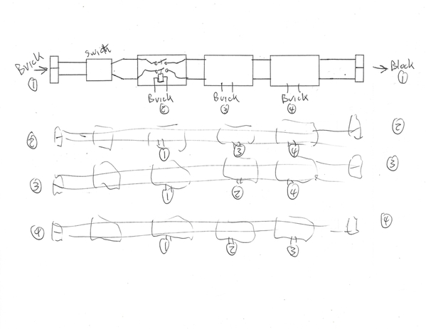
Here is a possible circuit explaining the 12 relays.  From the photo each column covers one power channel.  The brick power comes in at the bottom then flows through the switch and three relays in series.  All the coil wires sneak through holes to the back.  Clearly the magic happens on the other side of the board. My surmise is the relays are driven by the three "other" bricks in each channel.

I am still trying to sort out the terminal strip at the top.  Also the red wire on the right side may mean the relay coils are connected to the track sections instead of locally on the back of the board.

Cam

circuit 1

Attachments

Images (1)
  • circuit 1

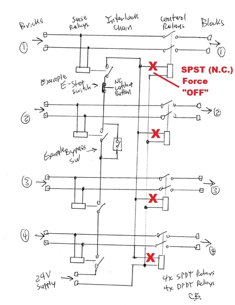
I agree that explains how 12 relays could be deployed...but I don't see how it performs any different/better than your 8-relay method.  The force-OFF switch in your method could be placed on the output relays (red X) and these switches would not need to be heavy-duty 10-Amp (or whatever) switches.

Block%20Power%20Interlock

Plus, with the presumed 12-relay method, the nominal condition is all 12-relays are "active".  And for heavy-duty relays which might draw 1 Watt per coil... that's 12 Watts of overhead.  OK, 12 Watts does not break the bank.  But all 12 relays carry the full load current per block...whereas with your 8-relay method only half of the relays carry full block power so lower capacity relays can be used for the sense function so less expensive relays could be used.

In the absence of further information, I vote for your 8-relay method which AFAIK meets the known requirements.


Attachments

Images (1)
  • Block%20Power%20Interlock

OK here are more photos, the toggles take that particular block off line, four toggles makes the safety feature total off. some of the fine wires on top of board go to micro pilot lights to tell which block tripped the circuit. the digital readouts for each block are...." I forgot".

This is hard to photograph. holding a flashlight ,camera and the board in position.and I don't like taking photographs because they always turnout poor.

Hope this helps the cause


 IMG_7938

IMG_7930IMG_7931IMG_7936IMG_7945IMG_7955 

Attachments

Images (6)
  • IMG_7930
  • IMG_7931
  • IMG_7936
  • IMG_7945
  • IMG_7955
  • IMG_7938
Last edited by clem k

Stan - in my diagram the control relays need high current contacts.  All the other relays and switches including the ones you added only need to handle to the current to the control relay coils.  This was a quick sketch,  I would probably select an lower coil voltage for the control relays like 12VAC, or perhaps DC - with the relay supply selected accordingly.

I agree with your comment on the power consumed by the always-on relay coils in both designs.

Clem - thanks for the additional photos.  I love reverse engineering.

clem relay question

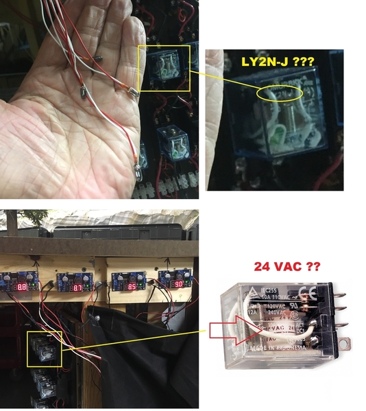
So for the record, could you confirm that all 12 relays are marked "LY2N-J" as it appears to be above?

And, if so, could you read the marking on the coil wrapping.  For example, in above the coil is repeatedly marked "24 VAC".  This tells us the relay coil voltage...which for the LY2N-J type relay might be 12V DC, 12V AC, 24V DC, 24V AC, etc.

clem k posted:

... the digital readouts for each block are...." I forgot". 

Yes, this is a head scratcher.    Those digital readouts are part of a DC voltage regulator module.  It's not clear to me why DC voltage is being used - much less 4 separate DC voltages around 9V DC!  Makes me think the relay coils are operating at 9V DC.  Interesting!

Attachments

Images (1)
  • clem relay question
stan2004 posted:

I agree that explains how 12 relays could be deployed...but I don't see how it performs any different/better than your 8-relay method.  The force-OFF switch in your method could be placed on the output relays (red X) and these switches would not need to be heavy-duty 10-Amp (or whatever) switches.

Block%20Power%20Interlock

Plus, with the presumed 12-relay method, the nominal condition is all 12-relays are "active".  And for heavy-duty relays which might draw 1 Watt per coil... that's 12 Watts of overhead.  OK, 12 Watts does not break the bank.  But all 12 relays carry the full load current per block...whereas with your 8-relay method only half of the relays carry full block power so lower capacity relays can be used for the sense function so less expensive relays could be used.

In the absence of further information, I vote for your 8-relay method which AFAIK meets the known requirements.


A few random thoughts-

Why couldn't you reverse the logic of the whole thing; use the NC contacts on the control relays and put the sense relay contacts in parallel? That way the control relays would normally be de-energized, no heating and no power consumption. Yes, if the control supply fails you would have no protection.

I'm guessing that the DC supplies were intended to permit the use of 12 VDC sense relays, but the filter caps in the supplies caused the sense relays to hold in for a while after the power was lost, so the 8.x volt setting was chosen to put the relays right on the edge of dropout to speed up the response to a power loss.

Because there are no inexpensive 18 VAC relays, the sense relay function is going to require a bit of fudge. I think the original design is a good attempt to use plain old stock parts.

I understand that the builder of the original unit may well have used what he had on hand. No criticism of the original design is intended.

Just talking........

gunrunnerjohn posted:

I have to think this is killing gnats with a sledgehammer.  Am I missing something?  Why not just remove the 120V power from the layout with a trip, why all the high current relays?  One big control relay on the input power and then any sensing you desire for the power districts.

That's a good thought too.

Add Reply

Post

OGR Publishing, Inc., 1310 Eastside Centre Ct, Suite 6, Mountain Home, AR 72653
800-980-OGRR (6477)
www.ogaugerr.com

×
×
×
×
Link copied to your clipboard.
×
×