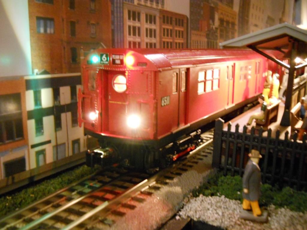
I have a RK Mountain and I want to replace the 6v headlight bulb with an LED.  I upgraded this engine with a PS2 kit but the steam kit only has one connection for the headlight and no extra lights. I also need to add LEDs for marker lights and the firebox glow like the original Locosound setup. I would like to run all three off the headlight lead. Is this possible?  I was hoping to buy 3 Evans Designs LEDs since they come with the resistor already added.  


(If there was a constant voltage board in this engine, I removed it when I did the upgrade)

Original Post

Replies sorted oldest to newest

Well after rereading the 'recent thread' it looks like Evans Designs LEDs are set for 9-18 volts which means track power.  I need to know how many LEDs can be run off a PS2 upgrade board(3V) with just one connection for a headlight.  If I use the ED LEDs it looks like they would be extremely dim if run off the board and not track power.  


So if I purchase 3-5V LEDs can 3 of these be run from the one connection for the headlight from the PS2(steam engine upgrade kit) 3V board?   Looks like I will have to add my own resistors too. 


I was hoping Dale H. would chime in, his knowledge seems to be all encompassing on things electrical!


There must be someone out there who has done this modification.  Thanks in advance.  I find this forum an absolutely amazing source of information.  

After more research and thought, I think I will run the firebox glow and marker lights off track power(2 new LEDs) as suggested by gunrunnerjohn and maybe change the MTH headlight bulb to an LED.  I don't want the headlight running off of track power.  Thanks for the ideas. 


Off to AZ tomorrow so it will be a while until I get back to this.  There is an outdoor Garden Railway Tour on the 10th and 11th in Tucson!   Going to cruise over to that. 

Originally Posted by gunrunnerjohn:
Perhaps you'll need to consider a similar thing if the voltage from the MTH board isn't up to the task.

John, 3V in PS2-3V refers to the voltage used by the digital processor; PS2-5V boards use a 5V processor.  PS2 incandescent bulbs are 6V so adequate voltage is available to drive LEDs; it's the type of signal (high voltage pulsed-DC) that requires consideration. The pulsing varies to maintain constant brightness across a resistive filament. As you know, LED brightness is proportional to current which represents a different type of load to the PS2 circuit. 


Originally Posted by pennsydave:
After more research and thought, I think I will run the firebox glow and marker lights off track power

Makes sense.  But out of curiousity, did your research determine that you can't tap into the PS2 outputs for Marker lights and Firebox glow?  That is, the hardware is there to drive those signals.  It's "just" a matter of finding a soundset to download that enables these signals but I'd think that knowledge is out there (perhaps in the PS2 forum).


If I'm not mistaken, the PS2 Marker outputs are meant to drive LEDs so they would be directly compatible - no resistor required.  You'd need to find a few crimped wires that snap into the unused positions in the harness connector housing. 


I have not installed a PS2 upgrade kit so I may have an overly simplistic view of the matter.

I know about the PS-2 battery voltages, just didn't realize that was what was being referred to.


The high voltage pulsing I think I'd deal with with a cap across the LED.  With the series resistor, that should smooth things out.  If it's really severe, I guess diode protection might be called for.  I wonder if anyone has a 'scope picture of that this looks like?


I've never tried to add lights to PS-2 locomotives, though I have on in the closet that I'm going to be looking at sometime.  Maybe I'll have a better idea how to add them then.  Now, ask me how to add lights to TMCC locomotives, I'm your man.

Stan,  The PS2 upgrade kit does not contain leads for marker lights and firebox glow.  My initial mistake when I installed it was I believe I removed a constant voltage board that controlled these lights in the RK M1 Mountain Locosound engine that I converted.  Did not know enough of what I was doing!   I assumed it was the Locosound board since there was nothing in the tender but the speaker and battery.  So any additional lights are going to have to come from track power or from the board powered headlight or maybe even smoke unit fan.  That is why I think I will just use track power for those two LEDs when I install them, if I have room for the wiring etc and can best figure out how to locate everything.


That ‘recent thread’ was just updated suggesting an Evans LED solution for the headlight.


Perhaps there are different flavors of upgrade kits, but the PS2 steam kit on the MTH site says it includes 2 Marker LEDs (tender-side) with wiring.  So if yours did not come with it, perhaps you can separately buy just the Marker assembly from MTH.


tender


Re the firebox, if your model has a red/orange lens, white or warm-white LEDs are not “rich” in red/orange light content relative to an incandescent for back-lighting thru a colored filter.  Some experimentation may be required to select LED color between white, red, orange, or perhaps some combination.  If going for the active firebox effect, I see Evans (and others) have flickering LEDs too.


Attachments

Images (1)
  • tender

Stan, the tender harness has marker lights but not the engine harness.  If you could get the wires up to the engine maybe that would work.  But I don't believe you can do it within the bounds of the 10 pin engine connector.  The other question is basically my first question.  Could I run 4 marker lights off that tender connection designed to run just two?   


I think I will leave the headlight alone and run the marker lights and firebox glow off of track power.  That seems to be the easiest solution. 

Originally Posted by pennsydave:
 Could I run 4 marker lights off that tender connection designed to run just two?   

Could you live with half the brightness?  The two marker LEDs in the tender are supplied by a fixed current circuit.  You could splice in an additional two marker LEDs as long as they are not white LEDs (which require higher voltage).  So if you're doing two pairs of red-amber markers it could be done with a little re-wiring but no new resistors. I know it's hard to visualize what half the brightness will be in an LED but it's not as bad as you might think and probably worth the tradeoff if you want the additional lights.


Originally Posted by pennsydave:

Stan, the tender harness has marker lights but not the engine harness.  If you could get the wires up to the engine maybe that would work.  But I don't believe you can do it within the bounds of the 10 pin engine connector.  The other question is basically my first question.  Could I run 4 marker lights off that tender connection designed to run just two?   


I think I will leave the headlight alone and run the marker lights and firebox glow off of track power.  That seems to be the easiest solution. 

Since this thread is alive again I'll throw in my 2 cents worth.


While I am sure that Dale's circuit would work fine for running the headlight LED off track power, I would leave it as is for 2 reasons.

One, you won't be able to turn the headlight on and off from the DCS handheld.

Two, if you ever run conventional, the headlight will be very dim.


If you are adding boiler marker LED's, I usually add these to the headlight circuit, using the MTH green marker LED harness. This has the two LED's wired in series. I also add a 390 ohm 1/8 watt resistor in series to set the current limit right.

Done this way the marker LED's turn on/off with the headlight.


If it's tender LED's you want, Stan's suggestion is the easiest way to go.


Rod

Originally Posted by Rod Stewart:

While I am sure that Dale's circuit would work fine for running the headlight LED off track power, I would leave it as is for 2 reasons.

One, you won't be able to turn the headlight on and off from the DCS handheld.

Two, if you ever run conventional, the headlight will be very dim.


Rod

If using the Cl2-N3 chip ,the the lighting is constant voltage.

Originally Posted by Rod Stewart:


If you are adding boiler marker LED's, I usually add these to the headlight circuit, using the MTH green marker LED harness. This has the two LED's wired in series. I also add a 390 ohm 1/8 watt resistor in series to set the current limit right.

Done this way the marker LED's turn on/off with the headlight.


If it's tender LED's you want, Stan's suggestion is the easiest way to go.


Rod


Hi Rod,


Do the 2 series marker LEDs (plus 390) change intensity with track voltage?  I'd think they would but perhaps it's so slight as to be negligible.  That would be good.


Originally Posted by stan2004:
Hi Rod,


Do the 2 series marker LEDs (plus 390) change intensity with track voltage?  I'd think they would but perhaps it's so slight as to be negligible.  That would be good.


Stan;

No the circuit is a constant voltage 5 VDC circuit. The PS-2 headlight, and consequently the marker LED's, all run at constant intensity, in DCS or conventional mode.


Rod

I have a question regarding the typical steam marker light connector.  Why on the 8-pin connector is the LED+ (pin 8) connected with a jumper to Marker2 (pin6)?  I understand Marker1 (pin 4) connecting through the 2 LEDs an then LED+, but the jumper doesn't make any sense to me.
 
Unless there is a nice amount of resistance before connecting to a cpu pin, it seems like it would at best waste energy heating a resistor, and at worst short the pin.  This is assuming that the PS2 sound file actually uses Marker2 at all.
 
Is the jumper providing an extra couple milliamps the LED+ in some cases?
 
Thanks,
 
Eric
 
 
Originally Posted by stan2004:


tender


Originally Posted by Eric Linz:
Unless there is a nice amount of resistance before connecting to a cpu pin, it seems like it would at best waste energy heating a resistor, and at worst short the pin.  This is assuming that the PS2 sound file actually uses Marker2 at all.


The Marker 1 and 2 outputs drive LEDs and current-sources putting out something like 10 mA.  Not that one can design a pure current source but current sources in theory have infinite impedance so even if shorted the wasted energy would be limited.  I never heard the "stability" reasoning that GGG mentions but taken at face value, then why not turn lemon into lemonade - break the loop in pin 6-8 and install an LED(s) of your choice to light up something else in your engine and maintain that stability.  Of course it would go on/off under LMK softkey control.

Post

OGR Publishing, Inc., 1310 Eastside Centre Ct, Suite 6, Mountain Home, AR 72653
800-980-OGRR (6477)
www.ogaugerr.com

×
×
×
×
Link copied to your clipboard.
×
×