


Rich-what switch machines are you using? With the dz1000 and 2500 there is a controller for the control panel. Two wires go from the switch machine to the controller for each turnout, then there is a power wire that goes to the switch machine and a ground to the controller. So each turnout would have a controller at the control panel end.
The DZ-2500 is wired a bit differently than the DZ-1000.
@gunrunnerjohn posted:The DZ-2500 is wired a bit differently than the DZ-1000.
Thanks, John, for pointing that out. The train stuff diagrams are pretty good, looking at them even I can wire them, the person my dad the engineer would look at my wiring and growl like a bear I had stolen its fish from.
I just got done wiring 25 DZ-2500, so it's fresh in my mind. ![]()
Rich -
From you photo on the first post it looks like you are using DZ-1000 motors. I am not sure if you will ever want to add non-derail, a signal lamp to indicate turnout position or something else that would require a relay like the DZ-1008 to be connected to your turnouts so below gives you the capability to do all.
The switch motor has three wires - power and two 'ground' (the yellow and green wires). For a simple connection the red wire goes back to the power terminal on your transformer. The ground from the transformer is connected to a whatever control mechanism you are using (Ross supplied or after market like a DPDT mom toggle switch). For the Ross controller (again three wires) connect the black wire to transformer ground. For the DPDT toggle switch connect the ground wire from the transformer to the center post of the toggle switch. Connect the yellow/green wires from the switch motor to the yellow/green wires from the Ross controller or to the outside posts of the toggle switch. You should be good to go.
If you want the pair of 072 turnouts to operate in tandem simply connect the yellow/green wires together then go to the controller/toggle switch.
You have no choice with the turnout yellow/green wires. Each must feed back to the control board. However you can use a common ground wire for all controllers/toggle switches. I don't know for the Ross controllers (someone else may have a good idea like a bus wire system) but for the toggle switches bring one wire from the transformer to the center post of the first toggle switch then connect a wire from that post to the next center post on the next toggle switch etc, etc.
With respect to the power wire (red) you can bring one heavy wire from the transformer to a central terminal and connect from there to each turnout motor. You may need more than one terminal so just connect terminal to terminal with some heavy wire.
In my case I have non-derail and DZ-1011R detectors (electrical tape over the sensor) connected to the turnout motors through a DZ-1008 relay. This means more wires under the switch machine plus a terminal for ground. I use European style terminal connectors. I have four 6-position terminals (the 12 position are easy to cut in half). One each for power, ground, yellow and green wires. I make all my connections for the switch motor, relay, DZ-1011R and non-derail to these terminals.
I may be wrong but I believe for non-derail to work track ground and turnout switch motor ground must be common to each other (ie connected together). I have a common ground on my layout and it works. I don't know if the function will work for separate ground systems.
Joe
Good morning!
I apologize for the delay in responding to you all. Everyone's advice has been very helpful in navigate my track layout.
I am working with DZ-1000.
Today, I am heading to my train store to purchase 2ea. left-hand #4 crossovers to replace the two O-72 turn-outs.
That being said, hopefully, I can then move ahead wiring about 10ea. of the track switches!
Joe Fauty, your detailed explanation for wiring the switches to the toggles/control button is just what I needed. I feel a bit more confident now as I approach the wiring of the switches.
I have seen post about non-derailing switches. How does the wiring work for that?
Why are you using European style terminal connectors ? Do you have a picture of your wiring that you could share ?
Thank you all for taking the time to guide me through this stage in my layout.
Rich
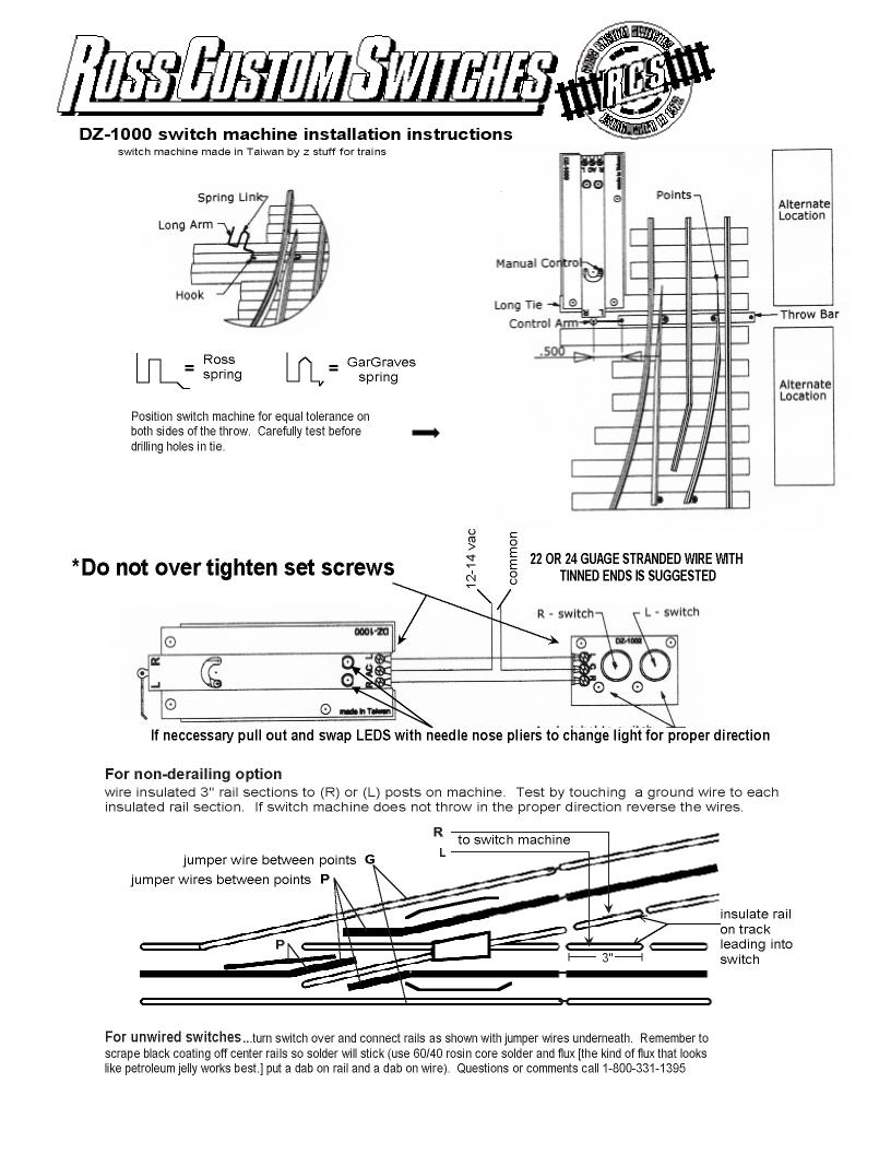
Here's the Ross DZ-1000 installation instructions, note the bottom of the page has the non-derailing wiring. The non-derailing wires from the rails just go to the right and left connections on the DZ-1000.
@1Irishrover posted:Today, I am heading to my train store to purchase 2ea. left-hand #4 crossovers to replace the two O-72 turn-outs.
Rich
Rich,
We know what you mean, but if you have to order your switches make sure you order two #4 left-hand switches. Ross does make a pre-built #4 left-hand crossover made up of two #4 switches and set at I think 3.5" C-C track spacing. This is for yards and is probably too close for your tracks.
Yep, got several of those in my yard, but I think he knows he needs real #4 switches.
I have seen post about non-derailing switches. How does the wiring work for that?
Rich - see above. The non-derail works by creating an isolated portion of the inside rail (ground) of a track before the switch exit. When a car passes over the isolated track it triggers a ground connect to the switch motor which causes the motor to activate and move the point rails in the correct direction. I don't like cutting into the switch track so I usually isolate the inside rail of the track section just before the turnout.
Since you are connecting track ground to switch ground via the left and right switch terminal only thing I would add is make sure the ground for both track and the switch motors are common to each other.
Why are you using European style terminal connectors ? Do you have a picture of your wiring that you could share ?\
Just a pet peeve of mine. Spade connect terminals are just fine also. European connectors were originally made so that bare wire could be inserted without have to crimp on a connect but the wires in mind were solid core. We use stranded so I got into using wire ferrules. I crimp the wire ferrule onto the wire and insert the crimp connect into the terminal. For me this is a rock solid connection. I have had wires pull out of spade style crimp connects (probably poor crimping on my part) but I have never had a wire pull out of a ferrule crimp. Once it is screwed into the European terminal connector it is not going anywhere.
Below is a typical wire ferrule

If I need to make jumper cables then I do below. However a forum member told me about a source that supplies ready made jumper bars for a typical 8mm pitch terminal. A good source for both the wire ferrules and the European terminals is Ferrules Direct
")
Altech HCL8-12 (8mm pitch 12 position) - got these from Mouser but they are expensive - $4 each for 12 position. I ended up going back to making my own.


With respect to the basic connection for a switch motor to a control board see below.

If you want to add an indicator light at the track (I use DZ-1011R with tape over the detector) then you need a DZ-1008 relay. The wiring gets a little more complicated. This is why I have 4 wire terminals under every turnout. For non-derail I run the wire from the track to the appropriate green or yellow terminal.

Attachments
Images (7)


")
Thank you Joe for the detailed advice and instruction on the wiring of the of the Ross z-1000 switches. I really appreciated the pictures as that helps understand the wiring as I learn this process.
Ron, I was able to purchase 2 each Ross Ready left handed #4 switches.
Gunrunner, I custom cut a piece of straight track to connect the 2 left arms of the switches.
Hopefully, I can get down to my "train room" and begin wiring the switch motors.
Thank you again to everyone who as taking time to share thier experience and advice.
Rich
Add Reply
Sign In To Reply

