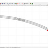
86TA355SR,

Let me add something. The pieces of GG that provide a 26.5° section of could possibly be used. You get the uneven rails that could be matched with a like piece until your curve ends, which is where you would even the rails.

You have to calculate the arc angle for the build style to arrive at an accurate inventory report or parts list as it is called in SCARM.

Finally, I don't think that you want to try to bend Atlas O.

There is a flex-tool tutorial on the SCARM website. help on the menu bar>select documentation> select working with flex tracks

Dave, sure you can do it that way. I use the flex track because I find myself cutting fitters and need specific degrees of arc. The wiggly snake thing doesn't work for me.

For example, I get the data for an easement track in RRT and then make consecutive entries in the flex-tool box to create those in SCARM before hitting the fix button.

MartyLJ posted:

Does SCARM work for ON30 layouts. I know I could use an HO  form but the spacing for O is mt concern.

I am not familiar with the track manufacturers that you would use, but there are many HO in the track library. If a specific track system that is popular is not there, one can send the manufacturer's line brochure and specifications on the track and Mixy will add it. here is a list of the included libraries

Which track system most is used?

There is an easy to access and use measurement tool that assists in setting the track centers and the spacing to the table edge and other objects.

There is also a Flex-track tool to create your own curves and custom length straights.


Last edited by Moonman

I have my final layout designed and ready to build the framework thanks to SCARM.

I absolutely love it.  Most of my design work is with Atlas switches and Atlas flex tool.

Question:  I tried printing with grids and all I get is the tiny 5" spaced dots.  Is there a way to convert the dots to lines in order to make the transfer from paper to open grid benchwork easier?

Thanks...   Tom


Unfortunately, no. Someone once speculated that the reason for the 5" grid was because base straight sections of track are 10". I primarily use RR-Track, partly because it has 6", 12", 24", 48" and 10'  grid options, and then sometimes enter the layout in SCARM for the arguably better 3D view. Once you draw your benchwork perimeter in SCARM though, the grid size doesn't seem to matter all that much, but I still prefer thinking in terms of feet vs 10".

Last edited by DoubleDAZ

The reason for 5 inch grids is the decimal system. 

10 inches being the controlling factor. Realize that the original is based on metric measurements, again, decimal, multiples of 10. Conversion from metric to decimal inch is much easier.   Story goes that the first Mars lander crashed because an engineer didnt convert meters to feet properly.  

  Much easier to count distances in multiples of 5 in. Since with the sizing of the small layouts, the number of inches is more important than the number of feet. Unless you are building a 4 foot by 8 foot layout.   Of course, when your laying out your support structure you are tempted to use 16 on center because of experience, but its just as easy to go 15 or 20 on center.   The Club will be building a new 1500 sq ft layout this summer, totally designed with SCARM. 20 inch on center supports is sufficient.

swav posted:

The reason for 5 inch grids is the decimal system. 

10 inches being the controlling factor. Realize that the original is based on metric measurements, again, decimal, multiples of 10. Conversion from metric to decimal inch is much easier.   Story goes that the first Mars lander crashed because an engineer didnt convert meters to feet properly.  

  Much easier to count distances in multiples of 5 in. Since with the sizing of the small layouts, the number of inches is more important than the number of feet. Unless you are building a 4 foot by 8 foot layout.   Of course, when your laying out your support structure you are tempted to use 16 on center because of experience, but its just as easy to go 15 or 20 on center.   The Club will be building a new 1500 sq ft layout this summer, totally designed with SCARM. 20 inch on center supports is sufficient.

Thanks for the suggestions.  I look forward to seeing your new 1500 sq ft layout design.

I don't agree that it's "simpler" to think in multiples of 5", but then I tend to mostly think in terms of inches or feet when laying out the room dimensions and space for the layout and the 6" or 12" grid in RR-Track works better for me. Once that's locked in, I again think in terms of 6' or 12" when laying out the benchwork for a layout topped with plywood. Once those are done, I just lay whatever track fits and don't care about inches or feet. However, it's a moot point since the grid is 5" and not likely to change.

I suspect the layout with 20" centers will be an open style layout with plywood used mainly in the yards or for cookie-cutter style roadbed. Using 20" centers for a tabletop layout means 4x8 sheets of plywood either have to be trimmed to 80" or the joints won't line up on a cross-member for support. At any rate, it doesn't matter what measurement one uses as long as they consider the potential ramifications.

And for the record, I don't know why Mixy uses a 5" grid in SCARM, that's a question for him to answer, I only mentioned what I read here once. I don't know what 5" has to do with anything other than being an increment of 10 and I admit it's far easier to quickly multiply 5's and 10's than it is 6's and 12's. Personally, I think that's all it is. Tell me something it 255" and I have a hard time visualizing that, but tell me it's 21' 3" and I can readily visualize that. Different strokes and all that.

DP posted:

Things would be simpler today if Jimmy Carter had his way.  He proposed, during his term in office, that we convert to the metric system.   I think the growing pains would have subsided by now.  

I agree. Now we're saddled with multiple systems on the same items. I never know what wrench or driver to pick up, so both sets are side-by-side. I think it's a conspiracy by tool makers.

Ken M posted:

I think that is one of the reason I don't care for Scram & had a hard time with it.  Working in construction for all my life inches & feet are much easier for me.

Ken M

It's surprising what a difference that 1" makes for some of us. I mostly use a 12" grid in RR-Track,  but every so often I change it to 6". I do work in inches when dealing with the property dialogs, just not increments of 5.

DP posted:

Yea, how about that Dave. Way back in '78 I was installing kitchen cabinets from Europe.  The cabinet company gave me a two meter metric folding rule.  Back then I could read each millimeter.  Now if it's less than a sixteenth, I need a magnifying glass.

Man, do I know what that's like. I keep a magnifying glass right by my chair.

I don't use a grid when using layout software. It doesn't help me with track placement. SCARM has a Start Point tool that can place the center rail at any point of the X and Y coordinates

if I need a room perimeter, I define it with a translucent object. Then I define the table, deck or baseboard(whichever you call it) and I have my palette.

I use the measure tool to determine edge spacing and track centers. (or the parallel start point tool) I also use it when leaving space for buildings and terrain objects or create placeholders or put the actual object in the plan.

I suppose I am more abstract in my approach. The grid just appears as a visual distraction.

FWIW, Mixy explained the grid size early on in this lengthy thread. I believe it has to do with the 2D interfacing with the 3D engine. Anyway, It can't be changed.

Last edited by Moonman

Hi all

The grid is a weak point in SCARM when imperial units are used and this is my fault as a developer. The problem with that is not the grid itself, but the rulers and how the ticks are displayed in deep zoom in/out. In order to be fast in each frame redraw, the internal calculation routine works with integers and the imperial grid step is stick at 5” because that is exactly 127mm, so the tick marks are drawn on the correct places. Yes, it is stupid to be like that and I will redesign my code to allow user grid sizing in some of the next versions. But I am still not sure how to render the tick marks when zoomed in imperial units, because I am metric guy and I am thinking decimal

Mixy

I've been messing around with Scarm, the Express version, since I uploaded it about a week ago.  As I am still new to it, I have much to learn.  Carl mentioned defining the room perimeter before he starts his track layout.  How do you do that ?  All I can do is place pieces of track on the screen.  Also, is there a way to scale down the track images when placing them.  After I have placed a few pieces of track, I'm out of room on the screen.   

Mixy posted:

Hi all

The grid is a weak point in SCARM when imperial units are used and this is my fault as a developer. The problem with that is not the grid itself, but the rulers and how the ticks are displayed in deep zoom in/out. In order to be fast in each frame redraw, the internal calculation routine works with integers and the imperial grid step is stick at 5” because that is exactly 127mm, so the tick marks are drawn on the correct places. Yes, it is stupid to be like that and I will redesign my code to allow user grid sizing in some of the next versions. But I am still not sure how to render the tick marks when zoomed in imperial units, because I am metric guy and I am thinking decimal

Mixy

Thanks for the explanation Mixy. I thought you had mentioned something some time ago, but I couldn't find it when I searched through the thread.

I get that 5" = 127mm and 6" = 152.4mm, but there is a tick at the 6" point and I didn't understand why there couldn't be a grid line at the 6" point until you mentioned the deep zoom in/out. So I get it now.

Be that as it may, I'm not sure the grid is really the problem for me. Like Carl said, the grid, especially the 5" grid, is a distraction and not needed for laying track. So, I turned it off and forced myself to think only in terms of inches. It took me awhile to get used to thinking in inches, but it did get easier as I went. I guess I got used to "drawing" objects in RR-Track before SCARM was released, so my thought process has been trained to do things the RR-Track way.

The bottom line is I like SCARM a lot and can't wait for the simulation feature to be released. I suspect that if I hadn't gotten used to using RR-Track before you released SCARM, the grid and other things wouldn't be issues for me. I often convert my RR-Track designs to SCARM for the 3D view and while it takes me a few minutes to get used to the differences again, once I do, things go just as quickly, so I'll continue to use both programs. My little test without the grid showed me that things are easier than I thought they'd be working in inches and I'm willing to admit that. Keep up the good work!

For me, the 5" between grid markings is a big plus.  My SCARM layout has been perfected and I will be ready to start the benchwork as soon as it warms up here.  I leave my table saw in the garage because it produces huge amounts of sawdust that I don'r want in my workshop/trainroom.

I am planning open grid modules for that eventual day when the layout needs to be moved or sold.  SCARM has helped me visualize the different heights of the benchwork that will make track and roadbed a lot easier to build.  The highest elevations will be flat while the lower elevations will have suspended roadbed and transitions.  If all the open grid were the same height, all the elevations would need to be built up.  This would drastically increase cost, work and make everything a lot heavier than need be.

Getting back to the 5" grid markings:  I overlaid geometric shapes on top of an additional layer above the layout to size up the various modules that will all be connected.  I used the ruler function to get the length and widths required and posted those dimensions on a printout of the layout.  I plan to use the grid markings to position the sub-roadbed.  I will make cardboard or corrugated patterns to help in cutting and placing the sub-roadbed.

I removed all the facia in order to get better dimension clarity and lost the inside opening in the 3D version, but that doesn't matter to me here.  I wanted an accurate plan view of the module sizes.

I hope the SCARM attachment works out properly.

Thanks...

Attachments

Last edited by Tom Burke

You have to use the Menu/Export feature to save an image as a bmp or jpg file for posting. I'd post it for you, but I'm sure you'll figure it out. It looks like a nice layout and something very close to what I had planned for a similar sized room until my wife said she wanted almost half for sewing and crafts. Happy wife = happy life.

I like SCARM too, but I'm not sure how anything in your comment supports a 5" grid vs a 6" or 12" grid. Even Mixy admits the 5" gird is a limitation in SCARM and he's working on providing options for different sizes. The reason I'm interested is because my tools are also in my garage and I will be building my layout in modules too. If there's some advantage to 5" vs 6" or 12", I'd sure like to know it. The rulers I use are all marked in feet, though I do have 1 tape that also has markings in increments of 10.

DoubleDAZ posted:

You have to use the Menu/Export feature to save an image as a bmp or jpg file for posting. I'd post it for you, but I'm sure you'll figure it out. It looks like a nice layout and something very close to what I had planned for a similar sized room until my wife said she wanted almost half for sewing and crafts. Happy wife = happy life.

I like SCARM too, but I'm not sure how anything in your comment supports a 5" grid vs a 6" or 12" grid. Even Mixy admits the 5" gird is a limitation in SCARM and he's working on providing options for different sizes. The reason I'm interested is because my tools are also in my garage and I will be building my layout in modules too. If there's some advantage to 5" vs 6" or 12", I'd sure like to know it. The rulers I use are all marked in feet, though I do have 1 tape that also has markings in increments of 10.

Thanks Dave...

I corrected my post per the above SCARM link

DaveJfr0 posted:

I just started playing with this software tonight to see if it was something I wanted to use to design a 2R layout. I saw another post on here suggest the scarm software as the best free option.  About 2 or 3 years ago, I had played with some old software years ago that i had gotten off the AtlasO website, maybe it was rrtrack-based, not really sure; I only used it to design two 4x8's combined together, a layout which no longer exists.)  

First thoughts on scarm…(using only the 2r atlas-o library to mimic what I had on the Atlas software I was using, but I like that it has Lenz 2R and others.)

1. flex track usability is really nice. (auto curve, cut off, etc)

The Flex Tool in the toolbox lets you specify a radius and arc angle when you don't want a free formed piece.

2. when placing switches or curves, clicking the piece of track and then selecting the orientation takes a long time and it's not so user friendly (I also kept selecting the wrong curve item and had to keep going back and clicking through the options to get the other orientation).  Would be easier to have pictures of all options (2 per curve, 3 per switch, etc) as clickable buttons instead of the 2-click selection. Otherwise it was nice to have the red cursor and the next selected track piece would auto connect to the red cursor.

Use the Start point tool in the tool box and specify the location and direction. 0° points East and rotates to the South for 90° and so on. Pick the point from the ruler where the cursor is located. look in the low left bottom for the coordinates or pick them off of the rulers. Then add 22.5° or whatever way you want it to point.

3. I found it hard to navigate the 450"x 156" border I set up for the room, especially zoomed in. (now realizing that the program thought that my room border was my trainboard rather than just the room dimensions.)  It would be nice to have the adobe-grab hand to move around the screen instead of having to constantly click the scroll bars when I want to move around, especially zoomed in.

Select a polygon in Figures from the libraries. Very bottom. Then draw your room outline. Next, when it's closed, set the position at 0 and the height at .015. Next, select color, Translucent(gray box next to color ) and select OK.  Then use the baseboard tool in the tool box to create the baseboard.

4. Moving pieces of track (or groups of track already connected) is unfortunately a 2-step process.  It just won't move when I select it and try to click/drag it, but I have to right click and select move first.  Wish it was easier to move stuff around and connect the groupings of track together (like if I copy/paste a group of track and want to connect the copy of it somewhere else, I found this particularly hard to do (in addition to #5 below).)

Disconnect (move) the adjacent tracks on both ends of the section that you want to move. Double-click to select all and then right-click and select move.

Another way to replicate, say, half an oval, is hold down the CTRL key, select the tracks you want, right-click, select copy, or CTRL-C, then right-click, select paste or CTRL-V.Then right-click the highlighted track and select move.

5. I hadn't figured out how to take two pieces of track already drawn on the board and connect them together.  I seem to somehow remember this being easier in the AtlasO software, but its been a few years.

In SCARM, you have to select one and move it close to other track point until one turns green then release the hold click.

6. I built a little yard ladder and was trying to measure the center to center measurement…there was nothing for the measuring tape tool to auto-align with on the track centers…I had to zoom in really close and click the best I could with what I thought was center and was able to see the 4" centers I was looking for.  Would have been much easier if each track piece had some points in order to align the measuring tool to (or align it to the baseboard, to measure track to edge distances, etc.)

When you have an open track joint or move a piece temporarily to expose one, right-click on it and select Parallel Start Point. A dialog box opens where you specify the center to center distance, to the left or right and direction of the new start point. That lets you c set the center spacing for a number reasons when laying the track.

Not bad for a free piece of software, so I can't complain, just making observations.  I will watch the how-to videos that I saw in a link above from the developer this weekend and see if they help make easier the experience I had tonight. I think I'm going to try to track down that AtlasO software I had used previously and put that on my new computer, so I refresh my memory and compare.

Atlas let go of that one and had Mixy create an exclusive version of SCARM that they offer on their website. They will get some features in the future that we may have to buy in the full version. Only Atlas track of course, in their version.

I hope some of these tips will help you. You already have a good feel for the software. There are some techniques to improve the 3D renderings, too, if you want some nice eye candy.


Tom Burke posted:
DoubleDAZ posted:

You have to use the Menu/Export feature to save an image as a bmp or jpg file for posting. I'd post it for you, but I'm sure you'll figure it out. It looks like a nice layout and something very close to what I had planned for a similar sized room until my wife said she wanted almost half for sewing and crafts. Happy wife = happy life.

I like SCARM too, but I'm not sure how anything in your comment supports a 5" grid vs a 6" or 12" grid. Even Mixy admits the 5" gird is a limitation in SCARM and he's working on providing options for different sizes. The reason I'm interested is because my tools are also in my garage and I will be building my layout in modules too. If there's some advantage to 5" vs 6" or 12", I'd sure like to know it. The rulers I use are all marked in feet, though I do have 1 tape that also has markings in increments of 10.

Thanks Dave...

I corrected my post per the above SCARM link

Tom Burke,

I use the Snipping tool in Windows. Open the layout, turn off the rulers and zoom to the maximum size of the screen. The open the Snipping tool and save the file with a name and file type .jpg    . Works for the 3D screen or anything you are looking at on your screen.

Type snipping in the search box. Right-click on the app in the results and pin to the task bar.

Hello DaveJfr0,

Thank you for your feedback. Here are my short comments on your observations:

1.

2. You can just drag and drop track pieces from the selection panel to the drawing plot. To connect the dragged track to another, already laid in the plan, make both end arrows to overlap and color in red and green and then release the dragged track.

3. Hold down mouse wheel (middle button) and drag to scroll in any direction. Rotate the wheel to zoom in / out.

4. Hold Ctrl-key and drag with the mouse to move. That is done in this way to prevent accidentally moving and shuffling the tracks already laid.

5. See 4. and 2. above.

6. There are workarounds about these measurements, but I will think over this to make it easier and more intuitive.

Take also a look on the SCARM help topics – most are short explanations, but may save you some time and eventual frustration with SCARM.

Mixy

Last edited by Mixy
Mixy posted:

4. Hold Ctrl-key and drag with the mouse to move. That is done in this way to prevent accidentally moving and shuffling the tracks already laid.

Darn, somehow I missed this in the documentation. It's a little hard to do with a touchpad on the laptop, but it works, so it's one less problem I have with SCARM. I do like that it's more difficult because I'm constantly accidently moving pieces in RR-Track. Once I get used to it, I'm sure it will get easier with my left pinky and thumb on the left button on the touchpad. Thanks for the tip.

Moonman posted:

Tom Burke,

I use the Snipping tool in Windows. Open the layout, turn off the rulers and zoom to the maximum size of the screen. The open the Snipping tool and save the file with a name and file type .jpg    . Works for the 3D screen or anything you are looking at on your screen.

Type snipping in the search box. Right-click on the app in the results and pin to the task bar.

Carl, for some reason I've never used the Snipping Tool in Windows. I generally just use the Win Key/PrntScrn combo to do a screen capture and then crop it, etc., with Picasa, but I'll start using the Snipping Tool because it's a 1-step process and it creates a smaller png, gif, jpg or mht file for posting. It also allows one to mark up the image, like circle something in Red, before posting. Thanks for the tip.

Tom Burke posted:

Thanks Dave...

I corrected my post per the above SCARM link

You're welcome. I was also going to mention the screen capture, but I see Carl added the tip about the Windows Snipping Tool and that's actually a much nicer way to capture images of your layout in both 2D and 3D. As you can see, there are folks here with all kinds of ideas on how to do things more efficiently, and not just about railroads.

Oh, and it's always useful to also post the SCARM file so people can download it and either offer suggestions for changes or parts of it for their own layouts.

Mixy posted:

2. You can just drag and drop track pieces from the selection panel to the drawing plot. To connect the dragged track to another, already laid in the plan, make both end arrows to overlap and color in red and green and then release the dragged track.

Now that I use SCARM more often, I think I need to go back and read through the documentation again because I totally missed this tip too and I'm constantly selecting the wrong orientation on curves, switches not so much.

DoubleDAZ posted:

Now that I use SCARM more often, I think I need to go back and read through the documentation again because I totally missed this tip too and I'm constantly selecting the wrong orientation on curves, switches not so much.

You can check also the SCARM Blog – the English version is always up-to-date and the changes in the newer versions of SCARM are mentioned first (sometimes only) in the blog. That is because updating and synchronizing of the documentation in all languages is difficult and takes more time.

Mixy

Add Reply

Post
The Track Planning and Layout Design Forum is sponsored by

AN OGR FORUM CHARTER SPONSOR

OGR Publishing, Inc., 1310 Eastside Centre Ct, Suite 6, Mountain Home, AR 72653
800-980-OGRR (6477)
www.ogaugerr.com

×
×
×
×
Link copied to your clipboard.
×
×