
Well, after tearing down the old layout and finally deciding on a track plan I was satisfied with, the new layout construction has begun.  I started on Halloween night and here's where I'm at so far.


The layout is constructed with 2 x 4's because that is what I had from my old layout, and it will be covered with 3/4" plywood, also from the old layout.  It is L-Girder with pre-drilled holes for the wiring.  I'm still deciding what to do with the walls, since this room was never designed to be the train room I have a lot of work ahead of me, but that's what is fun about this hobby.


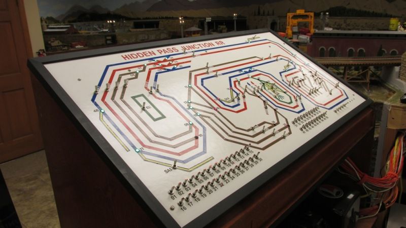
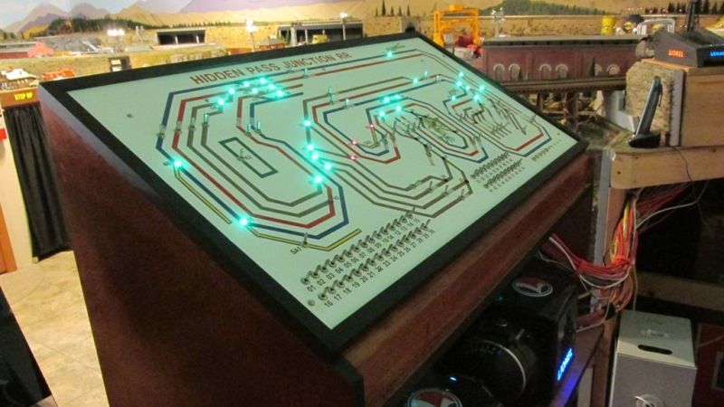
As for a track plan, I am using a hybrid of some plans that members Ace and Stewart designed for me using SCARM.  I am going to be using Gargraves track with Ross Custom switches, minimum 0-72 on the mainline, down to 0-63 around the roundhouse, and one smaller track with 0-54, but this track will be raised and include the city.


I know how much I enjoy seeing other peoples layouts in progress so I will do my best to keep the post updated with photos that hopefully will either assist, help or inspire others with their layouts.  I'm excited about the possibility of having the trains at least running by Christmas for the boys (All three of them)


Darren

Attachments

Images (6)
  • Craigslist 10-31-13 002: Laying out the framework
  • Craigslist 10-31-13 004: Yep, Hot Wheels tracks for the boys
  • Craigslist 10-31-13 008: Framework up!
  • Craigslist 10-31-13 010: Framework almost complete
  • Circus 039: L-Girder Benchwork Completed
  • Circus 040: Finished with the 2 x 4 framework and girder installation!
Last edited by Darren Caruso
Original Post

Replies sorted oldest to newest

Hey, I am also in western Pa too.  Nice room size Darren.  I been down my basement checking my room size also.  Nice pictures of you starting your new layout.

I am interested in your track plans and not sure how to view them. What does Ace and Stewart track plans mean?  Is the a way for me to see your track plans you going to use.


Andy 

Andy, I had started a new topic in this section of the forum titled "Asking for a little assistance"  members, Ace & Stewart, both helped with the SCARM track planning software by designing layouts that fit into my available space, if you look at my profile you can find that older topic and see the layouts throughout the postings.


Darren

I made some progress this week, I secured down the Homasote, and before the debate starts, I secured it down with drywall screws.  Mainly because I know me and glue, in addition to ease and timeliness.  This is the first time I have ever used Homasote so I will give the forum my 2 cents once I run a train or two over it.


Not building related but I did update my TIU this week also, another thing I had never done before.


Now I have to do some research on painting the Homasote, thinking of going with a flat black.


8-13-14 002

8-13-14 003

8-13-14 004

Attachments

Images (3)
  • 8-13-14 002
  • 8-13-14 003
  • 8-13-14 004

Darren,

This is the first I have seen your thread.


This looks serious!  I like your walk-in design, and you have a great space to work with.  Your wife must be very forgiving letting you build a layout on that nice carpet.


I see you have some DCS components there, and are using GarGraves with Ross switches.  I am thinking of doing the same when I start my next layout.  I have to reacquire some space.  One daughter is getting married next month, but the other one is the one who has all the stuff.  ;-)  I have a DCS but have not had much time to learn it this summer.


I saw you live in Western Pennsylvania, Beaver no less.  I live in Butler as my signature shows!  We lived next door to a Caruso family many years ago.  He had some nice postwar trains he setup at Christmas.  


I am looking forward to seeing your progress.  Many thanks for posting!

Thanks for all the kind words, I have been doing my best to keep the post as up to date as possible, this is my time of year to work on the layout so hopefully there will be many more posts and trains running soon enough.


Mark,

I have learned over the years that there are a lot of Caruso's out there, most of my family grew up in the southwest portion of the state.  This is my first layout with the Gargraves/Ross combination, so it will be a learning process as the layout progresses, but I enjoy learning new things.  And YES, I am very fortunate to have a supporting spouse and space to build a layout.


Gary,

I had used the foam roadbed in the past but I like the cork a lot more.  I can't wait to run the trains with the Homasote/Cork Roadbed combination.  I am hoping for a much reduced noise level.


Darren


Originally Posted by HJKSR:

I am starting to build a new layout using my old postwar 027 track. I would like to have parallel tracks. I am using 42" curves on the outside, but how do I make an inside parallel track conform to the outside 42"? Do I some how use 27" curves and a few 1/2 straights. Any ideas. This is not fast track.

Hi HJKSR,

It appears that the 027 track is sized based on the outside rail diameter. To have a symmetrical inside line on a curve of 042 with 027 on the inside, you would start with an 8" center rail to center spacing. This is by design of the track. To tighten that up to 4.5" to 6", you would have to put a small cut piece at 90º in the center of the curve.


Start a new post with your area or table dimensions if you want some assistance. Don't want to de-rail Darren's thread.


diagram attached.

Attachments

Images (1)
  • HJKSR 042 027 curves
Last edited by Moonman

Darren, nice work on the layout.


The homosote cork combination will definitely be a quiet layout.


the homosote will suck up the first coat of paint, so put down anything cheap. Then the second coat will give you what you need. I tried primer the first time. It was a waste of good primer, it sucked up so much. Latex is fine.


I can't tell from the pics, but there is a lumpy side and a fine grid side. I dind't pay attention and put the lumpy side up. Good thing it was only a 4 x 8 then.


Keeps the posts coming. Looks to be a fun layout!

Originally Posted by Darren Caruso:

Thanks for all the kind words, I have been doing my best to keep the post as up to date as possible, this is my time of year to work on the layout so hopefully there will be many more posts and trains running soon enough.


Mark,

I have learned over the years that there are a lot of Caruso's out there, most of my family grew up in the southwest portion of the state.  This is my first layout with the Gargraves/Ross combination, so it will be a learning process as the layout progresses, but I enjoy learning new things.  And YES, I am very fortunate to have a supporting spouse and space to build a layout.


Gary,

I had used the foam roadbed in the past but I like the cork a lot more.  I can't wait to run the trains with the Homasote/Cork Roadbed combination.  I am hoping for a much reduced noise level.


Darren


Darren,

Yes, and there are a few Boyces in Western Pennsylvania too.  ;-)

I have some GarGraves and some FlexTrak.  Separate ovals.  I don't know which way I will go on the new layout.


Have fun on your layout!

I finally feel like I have a model railroad in progress and not just another benchwork project that ends up getting tore down and rebuilt. 


I made some changes to the layout already, added a yard, moved the Roundhouse/Turntable "Future location".  Did some planning with sidings and structure location, which helped give me a better image of how the layout will look when completed.  I marked switch locations and started experimenting with laying Gargraves track.  I think I watched the Gargraves video three times and looked at every YouTube video out there, in addition to reading up on bending the flextrack as much as I could. 


As you can see I made my own bending jig with templates for the larger radius curves, the dogbone curves mainly use sectional curve track.


I hope to have the track completed sometime in October, I will post pictures when I get it done.

09-29-2014 004

09-29-2014 005

09-29-2014 006

09-29-2014 007

09-29-2014 008

09-29-2014 009

Attachments

Images (6)
  • 09-29-2014 004
  • 09-29-2014 005
  • 09-29-2014 006
  • 09-29-2014 007
  • 09-29-2014 008
  • 09-29-2014 009

I have progressed to the point where we finally ran an engine around the layout.


A lot of time was put into laying all the track, and there is still more to do but the current budget says I have to wait.  Being that this was my first bout with Gargraves track, and with using flextrack of any brand, I must commend this forum for its invaluable wealth of resources.  I was able to do A LOT of research before embarking on this track project and with a little planning, having the correct tools, and a little patience, seeing that train run around the track sure brought a smile to my face, and my oldest son, the other two were already in bed.


I am having a few issues with wiring the stainless Gargraves track, but I will ask about that in another forum and see what I can find out.


Here are a few photos of the train layout, and you may notice a few changes I made and the addition of the future Roundhouse/Turntable area.

10-07-2014 005

10-07-2014 004

10-07-2014 003

10-07-2014 002

10-07-2014 001

Attachments

Images (5)
  • 10-07-2014 005
  • 10-07-2014 004
  • 10-07-2014 003
  • 10-07-2014 002
  • 10-07-2014 001

Let me just say, "WOW, WOW, WOW"  I ran the three types of engines I have, note I'm classifying the steam into what I call large and small, and all you can hear after running them is the clickity clack of the wheels running over the rails.  


So "YES" I am recommending some sort of sound barrier if you are planning on building a layout.  I chose Homasote and it was well worth the money, just cut it outside, this stuff is messy and itchy!  There is no comparison vs running w/o a sound barrier.  I've constructed various layouts throughout the years, with 1/2 ' plywood, OSB board, etc. and I've had cork/foam roadbeds, hands down this is the quietest yet. 


I plan on using the rest of the month to work on wiring, so once I get something "solid" in place I will post what I did.  My oldest is already chomping at the bits to make a "youtube" video, so when he does I will post that as well.


Darren

Originally Posted by Moonman:

Drill a hole in the rail, pass stripped wire into it and use a #0 screw. Ask about the Screw it method.

Look at the May 1, 2011 post for the Hidden Pass RR

Moonman,

I have never seen anyone drill a hole and attach wires to rails that way.  While some would say soldering is better, I like this method.  Even though I was trained as an electronics technician 40 years ago and have soldered a good bit, I always had trouble soldering wire to rail.  I am thinking of giving your method a try.  Thank you!!

Mark,
It's not my method, but a resource I found. Ingenerio1 found it and liked it on many feet of track. It looks simple and is mechanically and electrically sound.
I believe a little later on in his thread was the drill size. I can't recall the source for the small screws right now.
 
 
Originally Posted by Mark Boyce:
Originally Posted by Moonman:

Drill a hole in the rail, pass stripped wire into it and use a #0 screw. Ask about the Screw it method.

Look at the May 1, 2011 post for the Hidden Pass RR

Moonman,

I have never seen anyone drill a hole and attach wires to rails that way.  While some would say soldering is better, I like this method.  Even though I was trained as an electronics technician 40 years ago and have soldered a good bit, I always had trouble soldering wire to rail.  I am thinking of giving your method a try.  Thank you!!


Originally Posted by Moonman:
Mark,
It's not my method, but a resource I found. Ingenerio1 found it and liked it on many feet of track. It looks simple and is mechanically and electrically sound.
I believe a little later on in his thread was the drill size. I can't recall the source for the small screws right now.
 
 
Originally Posted by Mark Boyce:
Originally Posted by Moonman:

Drill a hole in the rail, pass stripped wire into it and use a #0 screw. Ask about the Screw it method.

Look at the May 1, 2011 post for the Hidden Pass RR

Moonman,

I have never seen anyone drill a hole and attach wires to rails that way.  While some would say soldering is better, I like this method.  Even though I was trained as an electronics technician 40 years ago and have soldered a good bit, I always had trouble soldering wire to rail.  I am thinking of giving your method a try.  Thank you!!


Oh, thanks for the correction!!


Ingenerio1, thank you for sharing this method.  Yes, I was wondering about the source of the screws, but I am not ready for the permanent building stage yet.

With the help of my wife, we painted the Homasote, YES, the wife helped, and I know, I am very lucky!  I also know I should have done this before I ever put the cork roadbed or track down, but I'm not always the most patient person.


I got some cheap paint and had them get it as close to black as they could.


I also couldn't resist setting out the buildings so I can see how they'd actually look on the layout.


We picked up some "sky" blue paint and that will be the next project, to paint the tan wall around the layout blue.  I'm going to leave the green wall alone for now.


Darren

train october 14 2014 016

train october 14 2014 017

train october 14 2014 018

train october 14 2014 019

Attachments

Images (4)
  • train october 14 2014 016
  • train october 14 2014 017
  • train october 14 2014 018
  • train october 14 2014 019

Darren, that made a big difference! You can visualize the scenery. On the sky blue, paint a test area and go away for a while. Then come back and get a first impression. getting the shade that you like will be a pain.


I went with Tibetan Sky from Sherwin Williams in egg shell. I looked at the sky on a perfectly clear sunny day and chose what I thought was the color just above the trees on the horizon. It's very light, but it reacts to lighting changes. Oh, I also put their commercial white primer product on first to get exactly the shade that I wanted. The undercoat definitely impacts the color of the finish coat.

Last edited by Moonman

Thanks everyone for the kind words.


Leandro, I had actually started the layout benchwork last October or November, but with three kids it is not always easy to find the time.


Abuelo, I had a few fellow forum members assist me with a track plan, using SCARM, which I modified and am still modifying.  If you scroll back to page 1, I think there is a link to that post.  I started with pencil and paper, and it has evolved from there, but even my modifications start with that same formula.The lower portion is 38" and the upper is 48".  I wanted to be able to work under the benchwork without hitting my head, LOL.  


Darren

Until I looked I had not realized how long it had been since I posted an update, shame on me!  I made some changes to the far loop.  I wasn't happy with two similar loops so I divided them into one upper and one lower.  This division made the main line over twice as long, an added some additional scenery with tunnels, and as you can see from the pictures I added an upper track which will run separate from the main line.

11-28-2014 014

11-28-2014 015

11-28-2014 016

11-28-2014 017

Attachments

Images (4)
  • 11-28-2014 014
  • 11-28-2014 015
  • 11-28-2014 016
  • 11-28-2014 017

Darren:


You are my benchworking hero.  Thanks for posting these.  I'm going to do some similar work this weekend and you've inspired me.


I have a question: What sort of fascia will you be putting on this curved area?


Will this go all the way to the floor and be curved?


What are your thoughts in this area?


Thanks again for sharing.


Steven J. Serenska


Darren,

Thank you for the update on your layout progress.  It looks like it is coming along nicely!  Yes, time does fly when we are having fun with trains!!  


Question, how wide are your aisles?  Personally I don't need very wide aisles, as I'm pretty skinny for a guy in his late 50s, but I don't want mine to be too narrow for visitors.

Last edited by Mark Boyce

Thank you all for the encouragement.


Steven, I'm still planning that area, but I was thinking of using masonite down to the main framework, then skirting from there on down.  This way the skirting is at a uniform height all around the layout.  It's all still "up in the air" for that end of the layout.  We'll see, it may be modified as I come up with better ideas or see something that sparks my interest.


Mark, the original aisle width was another one of the reasons I changed that end of the layout, I had to turn sideways to get through there.  It is now, at it's narrowest point, about 22", and then widens out to a more comfortable distance.


Darren

Originally Posted by Darren Caruso:

Thank you all for the encouragement.


Steven, I'm still planning that area, but I was thinking of using masonite down to the main framework, then skirting from there on down.  This way the skirting is at a uniform height all around the layout.  It's all still "up in the air" for that end of the layout.  We'll see, it may be modified as I come up with better ideas or see something that sparks my interest.


Mark, the original aisle width was another one of the reasons I changed that end of the layout, I had to turn sideways to get through there.  It is now, at it's narrowest point, about 22", and then widens out to a more comfortable distance.


Darren

Thank you Darren, 22 inches is good.  Yes, I want to make sure I don't have to turn sideways when I build my next layout either.

Darren - just found this thread and WOW what an inspiration!  Can't wait  for your next report. I am also in the process of setting my layout up after several years of putting it on the back burner, but this Christmas it is going be running one way or the other.  I really like the dark color you put on the Homasote, can you share what color and brand it is?  Thanks...


Mike

Mike,


I purchased the paint from Home Depot, it is Glidden brand, I asked for a cheap flat paint and to make it as close to a flat black as they could, I am happy with the results, especially for $13.


George,


Unfortunately I do not, if you browse through this post from start to finish I think there is a link to another post in which forum members used SCARM, and designed a layout from my original drawings, but I have strayed from that, for various reasons.

I figured I would post some pictures of the layout before Christmas.  I decided to keep the Roundhouse and I have purchased a MRS 28" turntable, expected to be here mid January (Yes, I am excited!)  You can see the upper loop trackwork is almost complete, a few switches and benchwork odds & ends to finish up.  I have to "cut-in" the siding switches and finish the yard/turntable area trackwork, I still need more track.  It's a work in progress, but the plan is to have some scenery started by this time next year.  Hope everyone has a nice Christmas and a Happy New Year!


Darren

12-23-14 001

12-23-14 002

12-23-14 003

12-23-14 004

12-23-14 005

12-23-14 006

Attachments

Images (6)
  • 12-23-14 001
  • 12-23-14 002
  • 12-23-14 003
  • 12-23-14 004
  • 12-23-14 005
  • 12-23-14 006

I just love your layout!  The design, train room, lighting, and long straight sections make for such a nice looking display of your trains.  Should be fun to operate also !


I think you'll be happy you kept the roundhouse area, the MHRs TT will look great there.  A TT is on my 'must have' list of layout requirements because of detail projects, locomotive storage on the layout and it adds an interesting area for visitors to view.

It arrived and though it took longer than I wanted (Nobody's fault, just couldn't get to it due to kids being sick and work) The 28" Millhouse River Studioz Turntable is installed.  I know it has been stated before, but Alan is an excellent person to deal with.  You know when your happy with the box the turntable arrived in, your going to be happy with what's inside, and I am very pleased. 


I have a lot more work to complete before it is operational, but, to me, this was the most difficult step.


Darren

Attachments

Images (7)
  • MLS Turntable 001: The Hole!
  • MLS Turntable 002: UNpackaging
  • MLS Turntable 003: A siding I added this week
  • MLS Turntable 004
  • MLS Turntable 005: Finally
  • MLS Turntable 006: Approval from the wife:)
  • MLS Turntable 007

Darren


Nice progress on the layout.


I think the roundhouse will be great with Als turntable, nice selection.


Let us know if we can be of help with the build.  We have updated the instructions for the roundhouse since the kit you have.  You may find these helpful


http://www.korbermodels.com/Services___Links.html


Looking forward to seeing more post you have a great looking layout there.


Thanks everyone, I got the Turntable wired and running today.  Very impressed, even had the family playing with it this evening.  I had a few more yard items arrive this week so I will be spending most of my time working on the yard area with trackwork and wiring.  I will post some pictures, hopefully by next week, of some progress.


Rich, the completion of the Roundhouse is also on that list, as is working on the other Korber models I have to build.  Thank you for sending the updated instructions and the kind words.


Darren

I have been hard at work trying to improve the wiring for the layout and haven't got much else done, but I wanted to snap a few pictures to let everyone know where I am with the layout.  I am finding that there is more and more I want to do, so I am trying to prioritize by working on the layout functioning properly first, then aesthetics second.


Darren

03-03-2015 010

03-03-2015 011

03-03-2015 012

03-03-2015 013

Attachments

Images (4)
  • 03-03-2015 010
  • 03-03-2015 011
  • 03-03-2015 012: New wiring/lower control area
  • 03-03-2015 013: Picture my grandfather gave me, wife framed it, I am lucky!

Well, it has been a LONG time since I posted anything about the layout.  From Spring to Fall our family is busy with sporting events for the boys, Baseball, Hockey, etc.  So this is the time of year when I can get some work done on the layout.  I took a few steps back, but I think it will produce results that I will be much happier with in the end.  You will see from the pictures that the top level is no longer, there is a new area under construction for a trestle bridge, and all of the MTH buildings have been removed and will be placed together as one big city scene, instead of being scattered.


I have a large list of tasks ahead of me, and I will do my best to keep the thread updated.

480

481

482

483

484

485

Attachments

Images (6)
  • 480
  • 481
  • 482
  • 483
  • 484
  • 485

The top level was separate from the rest of the layout and served no real purpose.  I'm constantly trying to make each section of the layout have some purpose besides just filling up space.  Bottom line I wasn't happy and I think the changes will produce much more realistic scenes. 


As I "knock out" my list I will post pictures of the progress.


Thank you all for the kind words and support.


Darren

Thanks to my AMAZING wife, I was able to come home after work this afternoon and work on the base of the roundhouse.  I think I spent more time measuring and marking than actually cutting the wood.  I used a 4 x 4 sheet of 1/4" board and 1/8" Masonite.  I still have work to do, but I thought I would post some pics so you all could see the process/progress.

I had my little helper with me this evening. 

I also have been working on the Sandhouse and the bracing of the Roundhouse.

Darren


IMG_2355IMG_2356IMG_2357IMG_2358IMG_2359IMG_2363IMG_2364IMG_2365IMG_2366IMG_2360

Attachments

Images (10)
  • IMG_2355
  • IMG_2356
  • IMG_2357
  • IMG_2358
  • IMG_2359
  • IMG_2363
  • IMG_2364
  • IMG_2365
  • IMG_2366
  • IMG_2360

I traced the Roundhouse onto the 1/4" board, then I cut the board.  Once cut, I had an outline of the Roundhouse. 

I took the base over to the Roundhouse area and placed it into position, (I had also traced the Roundhouse when it was in place, so I had markings on the Homasote).  From here I measured and marked the areas where the track was positioned.  I used a Sharpie so I could see the lines when cutting. 

After I had cut the track areas from the 1/4" board I went and placed it into position, from here I measured again (I also had a tablet with a drawing of the area that I was using as a tool)  I marked areas from the beginning of the tracks entering the Roundhouse and the ends of the track in the Roundhouse.  Like I mentioned earlier, A LOT of measuring!

Because I did not have a sheet of Masonite large enough I just pieced together what I had.  I plan to use wood filler and sand the gaps later.  I placed the 1/4" board over the Masonite, traced the outline, referenced my measurements and drew the appropriate lines for cutting on the Masonite.

I next cut the Masonite, then cut eight 1/2" strips for in between the rails, and placed it over the 1/4" board in the Roundhouse area.  I had to go back and do some slight trimming, 1/8" in two places, but I wasn't disappointed in having to do that.

I used a table saw and jig saw for all my cutting, the table saw really helped reduce the time and create straight cuts.

I plan on completing the wiring for the track, bevel the Masonite in needed areas, paint the 1/4" board and surrounding yard area the flat black that I have, then work on the Masonite pieces, which will be painted grey.

I do plan on lighting the Roundhouse, I purchased LED lights and I am just waiting on the proper lamp shades.  I had purchased ones but they are too small for the 3mm LEDs that I ordered

Hope this helps,

Darren

I was able to get some work done on my MHRS turntable deck this week and I thought I would post a few pics of the process.  I am not completely done, the cab and ladders still need one more coat of paint and then installed.  But, hopefully I will have that completed tomorrow.

As far as the process, the railings were the most tedious and difficult.  The rest was not as bad as I first thought, especially when I first opened the bag of a "million" pieces.  A lot of filing and sanding to get it just right.  Once that was completed the parts fit together great, a little glue and some paint.

I am concentrating my focus on this area (The yard) of the layout before I move on, though I do need to do some trackwork in preparation for the trestle bridge, and some wiring also, lol, its a never ending process but that what makes it fun.

Darren

IMG_2367IMG_2368IMG_2369IMG_2370IMG_2371

Attachments

Images (5)
  • IMG_2367
  • IMG_2368
  • IMG_2369
  • IMG_2370
  • IMG_2371

PSU1980, I actually don't have a track plan to post.  I changed the original layout and have made several changes this year with more to come.  I will try to work on one in SCARM and post it or a picture of it.

86TA355SR, it is the standard arch that Al has with his turntables, you can get a PRR and UP versions, the PRR version is more squared and the UP version is more rounded, from the pictures I saw.

Caljah, thank you, I checked out your thread and it looks like you are well on your way, but if I see anything I think I can help you with I'll let you know, in the meantime, if you have any questions, please ask, and I'll do my best.  A lot of what I have learned in this hobby has come from trial & error, asking questions and reading/watching videos.


OK, I was able to "throw" something together with SCARM tonight, which I took a picture of.  I also finished the turntable, so I took a few pics of that too.

As you can tell, there is a reason I am not a computer aided drawing technician, LOL!

I plan on taking the SCARM printout to Staples and have it resized to 18 x 24, then use it as an outline for my Control Panel.  That project is "down the road"

IMG_2372IMG_2373IMG_2374IMG_2375

Attachments

Images (4)
  • IMG_2372
  • IMG_2373
  • IMG_2374
  • IMG_2375: Someone is happy Dad fininshed the turntable!

Carl,

I didn't know this was available, but I'm definitely going to start researching it now.  I purchased a few toggle switches in order to have the ability to power on/off tracks.  Having indicator lights for the switches would also be a nice feature.  After I get some more work done on the roundhouse area and the trackwork for the trestle section, I might have to course correct and make the Control panel/remaining wiring priority, and set other projects aside.  Let me see what I can come up with.

Thank you,

Darren

Darren,

Here's the SCARM files when you want to play with it. It's in the objects library>Symbols-Square tiles. At the bottom of the library there is a transparent tile. It's hard to see-it's transparent-LOL! I have only used it to close the frame. Don't know if you can use it for the fillers.

Drop me line if you have any questions when you work with it.

there's some good threads on the control panel wiring with LED indicators.

Attachments

Last edited by Moonman
Moonman posted:

Darren,

Here's the SCARM files when you want to play with it. It's in the objects library>Symbols-Square tiles. At the bottom of the library there is a transparent tile. It's hard to see-it's transparent-LOL! I have only used it to close the frame. Don't know if you can use it for the fillers.

Drop me line if you have any questions when you work with it.

there's some good threads on the control panel wiring with LED indicators.

Hi Carl,

Just an Fyi. The only thing I see when I open the Scram files are code, no photos.

Seacoast,

You have to download them to your machine an open them on SCARM there. They default to a text when you open them in a browser. They are not browser based. Right-click-select "save target as"- land it and open it with SCARM.

It's only the design that I made for Darren. I may have turned off some settings to remove the block outlines.

AFAIK, when someone saves a photo (menu/export) of a layout and then closes/saves the SCARM file, the next time someone opens it, SCARM looks for the photo (bmp/jpg). If the photo is not uploaded/downloaded with the SCARM file, it can't find the photo and SCARM pops up an error notice. Just close the popup error window and let SCARM finish opening. At that point, you can use the menu/export option yourself to save a photo (bmp/jpg) to your PC. The photo is the same as what you see in SCARM, just without the squares and is what you'd use to print a clean version to mount on your control panel.

If you don't need the photo yet, just resave the SCARM file and the next time you open it, there won't be an error because it will no longer be looking for a photo file.

Darren,

I was certain that I had posted comments on your excellent layout way before now, but after going through the entire thread, I cannot find my posts - I must have not posted! What first caught my attention on your layout was how you made the legs, which are exactly as I did mine such that the frame 2x4's bear directly on top of the leg, and not on the bolts that attach the legs to the frame. Later on, Moonman mentioned the method of connecting the power wires to the track, as I shared back in 2011.

Although perhaps a bit late now, I would like to share how I did my control panel, in case it may be of help.

I used 1/4" mylar tape to represent the track, and did the best I could to have all four levels readily visible. I used toggle switches (On/Off) to control the power to each main track district, each siding, and each spur. I thought about adding LED's to indicate whether the tracks were on of off, but it was too much. Instead, I mounted the switches right on the panel tracks, and let UP indicate ON, and DOWN indicate OFF, and this works fine. By the way, the toggle switches actually control relays that are mounted in close proximity to the tracks.

Momentary ON-ON with center off toggles control the switch tracks or turnouts. I did not want to crowd the track area with yet another switch, so I numbered the turnouts and mounted the switches at the bottom of the panel. To indicate the position of the turnouts, I use bi-color LED's - GREEN indicates straight-through track (even if the turnout points are actually curved), and RED means diverging track. These LED's are driven by my Non-Contact True Position detectors, and they work better than I ever expected.

Here are two images of the control panel, first with the all the lights on (fluorescent and others), and then with just the lights I normally have on when I run the trains. With the latter, the room is not quite as bright, and the LED's are almost a bit too bright. (The camera makes up for the brighter and darker room, and makes the area behind the control panel appear opposite of how it really is.)

Good luck, and congratulations on your layout and your progress! Make sure to keep us posted.

Alex


Last edited by Ingeniero No1

Alex,

Thank you, I really appreciate your input.  How you constructed your layout greatly influenced how I built mine, especially the leg construction.  Also thank you for taking the time to explain how you built your control panel, its not too late, that project is still in the planning phase and I appreciate the information you provided.   I'm still unsure of how big or small I want it, type of material, etc.  But the wiring is holding me back at this point, once I have a blueprint of how I need to wire it, then I'll be a little more confident.

It is actually ironic that you posted when you did, two nights ago I was reading your article about the trestle bridge construction and commenting to my wife about your layout (the trestle bridge is the next major project so I am trying to gather as many ideas as possible).

Again, thank you,

Darren

Darren,

One detail about the control panel: In the past, I had used aluminum sheet for the panels themselves, and this made it easy to mount most switches, annunciators, etc. For this current panel, I used 1/4-inch masonite, and it worked OK.

However, if I had to do it again, I would opt for 1/8-inch masonite, and add stringers for rigidity, as needed. The reason is that a lot of the through-the-panel mount toggle switches and LED's barely accommodate the 1/4-inch panel thickness. Just a minor detail.

Alex

Last edited by Ingeniero No1

Thanks everyone for the kind words, cut A LOT of wood the last two days, basically piecing together left over 3/4" plywood and 2x4's for the city area/mine site, and trestle extension.  If I get anything accomplished tomorrow evening I will post some pictures, Monday at the latest.  I'm trying to get the woodwork completed, Homasote cut and pieced together, trackwork installed, and paint whatever needs painted with the flat black I have.

Darren

Well, I got a few things done, never seems like you make any progress until you go back and look at the previous pictures, this evening or tomorrow I will work on the trackwork.  Hopefully, I will have the trains back to running.

I raised up the base of the trestle gorge, painted some areas that needed to be painted, including the base to the roundhouse and the base I made for the sandhouse, and tacked in the cork roadbed.

Darren

IMG_2376IMG_2377IMG_2378IMG_2379IMG_2380IMG_2381IMG_2382

Attachments

Images (7)
  • IMG_2376
  • IMG_2377
  • IMG_2378
  • IMG_2379
  • IMG_2380
  • IMG_2381
  • IMG_2382

George,

The black areas are just Homasote painted, same with the grey areas.   The first gallon of flat black paint I asked for at Home depot  came out dark grey, the employee stated this was the darkest she could get it, the next gallon I bought, I asked for the same thing, flat black, and I got flat black, needless to say, it was a different employee.  But I like both colors, nothing wrong with a little contrast, its going to get covered in the end anyways.  I am also using cork roadbed.

I'm about 40% done with the trackwork this morning, possibly after lunch it will be completed enough to run a test train or two.

Also on my "to-do" list is making a jig for the trestle bents.

Darren

Darren,

Your Layout looks great!  The black/grey gives it a great contrast. I like your trestle area too, I am sure that will look cool when your done.  Man, You work FAST! I like the way the Gargraves track with wooden ties and Ross switches came out ( track brand I am guessing you are using). The more I look at your layout I am tending to like the Gargraves look better than my Atlas  &, making me rethink my track selection.  Your giving me inspiration I need to get going on my layout as my 11 year old says what's with the trains in the attic aka the "carpet central".

Did you use Gargraves Flex for the curves or Gargraves sectional curves?

Last edited by Seacoast

I don't want anyone thinking I'm not working on the layout, just focused on finishing the roundhouse.  I posted these pictures on the Electrical forum, it shows the LED's I installed in the roundhouse.  Once I get the wiring to my liking I will begin working on the roof.  Its snowing here, so painting the remaining floor pieces and roof might have to wait to a warmer weather day.

Darren

IMG_2387IMG_2388IMG_2389

Attachments

Images (3)
  • IMG_2387
  • IMG_2388
  • IMG_2389
PSU1980 posted:

I m not familiar with SCARM - Where would I get it and is it difficult to use.

http://www.scarm.info/index.php

If you're not familiar with layout design software, it will take a little time to get used to how it works, but there are plenty of tutorials to point you in the right direction and there are plenty of layout files you can borrow to help you get the hang of things. It's well worth the time/effort and will save you countless hours over paper and pencil. Just like putting track together on the fly though, it's not without it's frustrations trying to figure out what works and what doesn't. The difference is you're not buying track just to find out things won't fit. If you aren't already sold on a particular brand of track, it will let you compare the ones you're interested in to see what can be done with the sectional track each offers. And, if you can't figure something out, just post the SCARM file and someone will help fix things.

Sorry guys, been away at training classes for a few days.

ATANZ:  Honestly I have no idea what the grade % is.  That curve is made up of 0-63 Gargraves track + sectional track, from the start of the curve to the end of the climb is approx. 18-20' in length and it is 6.5" in height.

PSU 1980:  SCARM is free, you can find it by typing SCARM into any internet search, and it does take some time to get used to, depending on how you wish to use it.  I like to hand draw A LOT of things, but I did mess around with it just to get an idea of how much track I needed, and to make a nice picture for my future control panel.

The weather is trending towards above freezing points today so I am hoping to get some wood cut so I can complete the work on the upper area.  Once I get a few more switches, the track work will be complete and I will start wiring the switches/blocks/etc, in additional to working on the Control Panel.

Darren

I'm in a phase now which I refer to as "Realistic Progress".  There are 15 things I want to work on at the same time but I have to keep  re-prioritizing.  First and foremost is to get the trestle bridge area complete so I can get back to running trains.  Everyday my little one asks "Daddy can we run the choo choo's today?'  I am pushing for Christmas, we'll see how it goes.IMG_2505IMG_2507IMG_2508IMG_2510IMG_2511IMG_2512IMG_2461IMG_2460

Attachments

Images (8)
  • IMG_2505
  • IMG_2507
  • IMG_2508
  • IMG_2510
  • IMG_2511
  • IMG_2512
  • IMG_2461
  • IMG_2460

Darren, You have made great progress.  The trestle area is shaping up nicely.  I can see that is a top priority if your child is asking about running trains.  Do you have an area that you could run them back and forth in the meantime?  Do you fave the trestle ready to put in place?  I am assuming so, if you think it is possible to get it going by Christmas.

Mark,

I do have the trestle bents built and stained.  Due to having little space between the bridge and the background area I want to complete that area, at least with the painting of the rock areas, before I start to build the trestle bridge into its place.  Once I get that done,  "I think" I should be able to construct the remaining portions of the bridge relatively quickly.

I've been working on the rock molds this morning, and I will continue with that tomorrow as well.  Maybe by the start of next week I can begin the bridge.

Darren

Darren Caruso posted:

Mark,

I do have the trestle bents built and stained.  Due to having little space between the bridge and the background area I want to complete that area, at least with the painting of the rock areas, before I start to build the trestle bridge into its place.  Once I get that done,  "I think" I should be able to construct the remaining portions of the bridge relatively quickly.

I've been working on the rock molds this morning, and I will continue with that tomorrow as well.  Maybe by the start of next week I can begin the bridge.

Darren

Darren,

 I just read this now, and don't know how permanently installed your fine looking trestle is as shown above, but you were 110% when you said what I bold-faced in red, in the quote. It is much easier to finish the slopes, rocks, etc. behind the trestle before it is in place. Even if you have to delay the project by a couple of days, it would be well worth it to delay the trestle permanent installation, or to temporarily remove it and work on the area surrounding it. 

Either way I know that it will look great when you are done with it (and post a few pictures)  

Thanks for sharing!

Alex

Alex, I designed the bridge so that it can be taken out with ease.  The track is glued to pieces that I bent to the same radius as the curve, so it acts like one large rigid curve which just lays on top of the bridge.  After the removal of a few track screws, the track can be removed then the bridge removed.

I have A LOT more work to do on the scenery around and behind the trestle.

Darren

Thanks guys!

1Drummer, let me know what pictures your looking for and I will see what I can find, or take a few new ones.

Mark, that little boy loves trains, or as he refers to them as "Choo Choo's".  Every day he asks me if I'm going to go work on the choo choo's, followed by "Can we go run the Choo Choo's?"  

Darren

I don't think a slide show is possible for all of the pictures I have ever posted, you can only post a few pictures at a time.  As for the bender, I made templates using wood for all of the curves that are custom radius and sectional track for most of the 072 and 0-80 curves.  I used a 2 x 4 piece of plywood, measured and cut the template from 1/4" masonite, secured the masonite to the plywood, then bent the gargraves track as per the instructions.  I used a dremel and cutting discs to cut the track, then filed the track before re-installing the track pins.

1drummer posted:

Seems I'm looking at 2 different, but very similar layouts..or my dementia is starting early.


From your thread, somehow I got on 

https://ogrforum.ogaugerr.com/t...yout-update-01302013


And that's where I saw the track bender.


I must confess, Anheuser Busch products were liberally involved 

That bender is gold. Designed by a guy named Norm from Az. 9Norm's Model Supply) he was working with Atlas. It was the only tool to curve Atlas flex. Then, he passed away (2013?) and no one picked it up, saved it etc. There were different roller sets for 2 rail and 3 rail.

If you ever find one, have it reverse engineered and build more.

I decided to edit the topic title now that its been 2+ years.  Felt it was appropriate due to the work that's now being completed on the layout.  I switched from the scenery work to electrical, mainly switches and power blocks.  Here are some pics of the control panel I've been working on, one thing for sure - I have a new appreciation for the worker who applies pin-striping to any vehicle!

Darren

IMG_2600IMG_2601IMG_2602

Attachments

Images (3)
  • IMG_2600
  • IMG_2601
  • IMG_2602

George,

Thank you, I used 1/4" plexiglass with auto pin-striping.  Since I have the MTH DCS system I am using the toggles for track power, the other things that look like buttons are the LED holders.  My plan is to have them illuminate green when power is applied to that particular section of the layout.

I do plan on placing 1/2" white numbers above the corresponding switches on the control panel, this way I, or any other user, can look at the control panel and determine what switch they want to operate, then use the DCS remote to operate the switch.  As I am wiring the switches I am labeling them in order on the DCS remote, just trying to simplify things as much as possible.

Darren

Hi Darren,

Just stumbled upon your layout a few days ago on Youtube and decided to check the OGR forum for progress. Seems you've come a long way since then. I hope all is well, and wondering if you've progressed much since your last post in January. I'd sure be interested in a current video or pictures, and I'm positive the members that have been following would also! Of course, when you have the time.

I've seen the earlier sketches of the layout and I'm curious if the plan has changed much. I plan on rebuilding my layout soon, the existing layout is an around the room with 2 duck unders, but I would like to go with a similar walk in style like yours. Would it be possible to indicate the critical dimensions? I've attached an image of your posted plan with radius & dimension lines indicated to make this as easy as possible for you.

Thanks,

Joe Kunka

Darrens layout 1

Attachments

Images (1)
  • Darrens layout 1

Joe,

I haven't done as much work on the layout as I wish, in fact, I plan to make some changes to the left side of the layout, just not happy with how it has turned out.  I was running the trains with my son this morning and went to make a short video... the camera battery needed charged so I wasn't able to make a video.

I hope to complete some work starting in the yard and moving around the layout in that direction until I reach the left side then start the necessary changes.

As for your dimensional drawing I'll do my best to provide the answers your looking for.

  • From left to right the room is approximately 27' long
  • The "G" line you drew is approx. 12' in lenght
  • From top to bottom, the total distance is about 18'
  • The 'F" line is close to 30"
  • Radius A & D are 0-72
  • Radius C is 0-80
  • Radius B is 0-63


Ironman,

The control panel is not functional yet, the toggle switches are from some famous on-line auction site, lol.  They are SPST, just designed to turn power on/off to sections of the layout.


Darren

Hi Darren,

Thanks so much for the quick reply, this should help considerably! I was using your video, following the Y6B around,  to get a sense of how my engines will look in a similar space. The Y6B looks comfortable and that puts me at ease!  

I built my layout over 15 years ago, and was gung-ho for about the first 6 months, building all the benchwork and getting 90% of track laid. I played around with some yard trackage and wiring improvements for the following 6 months and haven't progressed since. I think progress stopped because I wasn't totally happy, probably the duck unders are what killed my motivation. With a 13 x 23 inch space, not bad by O gauge standards, I'm limited since I love articulated engines and have kept my minimum radius to 072. I can drift into some un-satisfactory areas, where my boiler is for one, for a reverse loop or hidden trackage if the need should arise.

On and off over the years, I've been sketching new track plans on my train ride to work. Your layout has given me renewed inspiration!

The best thing about a layout, once you get the trains running...there's no real rush. Have fun, progress as time allows and take your time. I doubt anyone is ever totally satisfied and finished. Besides running the trains, the fun is in the building and learning new skills along the way!

Looking forward to a new video!

Joe (ironman1)

Joe,

I hear you completely.  For me, once the weather breaks here in western PA, I am running from one practice or game to another, my boys play hockey, baseball, golf (and I golf too!), so from April to September/October work on the layout is at a standstill, I just do not have the time.

This is the third layout I've constructed in the basement since 2007, with this being the most complete one.  I just need to fix the left side; not enough space to walk through comfortably, too cluttered, etc.  Basically, it was not planned very well because it wasn't planned at all.  The rest of the layout I am happy with, a few touch ups, scenery, two buildings to purchase and build, and that area will be 90% (I have figures, trees, ground cover, ballast, cars all sitting in boxes waiting to be put on the layout).

I am currently planning the re-do for that area and will continue to plan with the hopeful construction to being in 2018.

I'll try to get a new video/pictures posted this week.  

Darren

Good to hear of your progress, and I can understand the reasoning of a break.  When I finished the mainlines  of my layout, I was done for a while and just ran some trains.  That was 11 months ago and now I am motivated again.  Your layout looks awesome and I hope you have an easy time adjusting the one side of  the layout.  It is never done.  I look forward to your update. 


Hi Darren,

I had the same with my kids, and that's real important. Sports build character and keep the kids out of trouble. No time for trouble. The kids grow up too fast. Do it now, while you still have the steam.

Of course then, hopefully there's grandchildren and that's another story.

Enjoy the kids, run the trains, continue the layout when you have time.

Joe

Hi Darren,

I apologize for being fixated on your layout but after watching your existing video multiple times, it seems the trains are following each other on one continuous loop. It didn't seem obvious the first few times I watched the video and after reviewing the last track plan you posted, I believe that's the case. It's a little confusing where the loops overlap each other. I actually thought you had 2 independent loops. Am I correct?

Thanks,

Joe

Joe,

No problem, yes, it is one loop.  I had two separate loops but decided on one larger loop.  I like the fact that it takes almost 6 minutes for the trains to get back to their starting point, and if I can get the layout to where I want it will add another 2 minutes to the loop time.

Once I do that I am going to use power districts to control the amperage.  I can currently run three trains on the loop, but I plan to run four once the adjustment is made.  I also plan to use the upper level as a logging line, so I will be able to run a smaller logging train on that loop.  That will give me the ability to run 5 trains at once, which the big kid (ME) likes.

I started working on the scenery last night and today.  When I get a little further along I will post some pictures.

Darren

Darren,

When I realized it was one continuous loop I liked the plan that much more! It wasn't obvious when you see the trains passing each other. So cool.

With my Grandson, he's a little over 2 & a half, and he loves watching them run. I run 3 at once on 2 loops and have to be dilligent with the ones following each other since that is the shorter loop. It's a little tough since I'm trying to keep a hold of him on a step ladder so he can see, and juggle DCS & Cab 2 controllers!

Thanks for the quick reply. Looking forward to the updates.

Joe

Joe,

Thank you, I'm glad I'm inspiring someone, LOL!   

When I run the trains (And I'm just using DCS) I start them up in order from the furthest away to the closest, then, in that same order, set the engine speeds one by one.  I usually run between 18-20 scale mph, that's fast enough for me.  I have noticed with larger trains (Meaning the entire length of the train) I have to increase the speed by 1-2 mph to keep the spacing equal, otherwise the smaller ones catch up, then I have one long train.

I am looking into the wifi system from MTH, I think the kids will identify with it more, especially in this day and age.  We'll see if it speeds things up a bit when going from engine to engine.

Darren

Hi Darren,

Probably a stroke of luck that I stumbled upon your video. Since I’ve been bored with my current layout, design wise, I’m frequently looking for layouts, with an engine facility that appear to fit into my floor space. My 3 EM-1’s, 5 Y6B’s & an Allegheny have been my Achilles heel!

My existing around the room plan with an inner island reverse loop, and a minimum radius of 072 up to 0118 isn’t horrible, I just hate the 2 duck unders mostly. All my engines run around without hitting each other at least. I really want to include a 34” turntable and roundhouse and from what I can tell, your engine facility looks just about the size I can shoe horn into my space. If I had an extra 3’ width and 6’ length I’d have a little more flexibility, for an easier walk in design.

But once again, that continuous run on yours is what really sold me. I don’t quite have your space but, if I fold over the left side of your layout and compromise I can just get a similar run. I've attached my plan.

Joe

TrainLayout_12.5 x 22.5

Attachments

Images (1)
  • TrainLayout_12.5 x 22.5

Hi Darren,

Just before I left work I posted the proposed layout. I had some free time at work to refine my sketches. Although I could use smaller radius curves I wanted to see what would be the widest radius I could squeeze in. Not much room for a walk-in! :-) I can still go another 3 feet to the right if I move my access doors to my boiler and hot water heater... and very possible. Still a work in progress.

On my ride home on the train, I thought, have you considered running 3 trains as a lash-up. Not connected, but independent, spaced a safe distance apart. Theoretically, they should stay that same distance apart, no matter what the length of each. That's of course, if you're interested in is just watching trains run. I suspect that there will eventually be one catching another, but it may take awhile. I think I'm going to try it.

Joe

Joe,

I like the proposed layout you came up with, if you can squeeze another 3' to the right your room will almost be the same size I have, minus a few inches in length. I actually have a 28" turntable, which accommodates all of the engines I currently own.  The lash-up is a great idea, I'll have to give it a shot as well.

What program are you using to draw your layout?  I had originally used SCARM, but I'm having any success with installing the new version.

Carl,

I've been referring to the "left side" of the layout based on the drawing Joe posted of my room space.  But yes, the area near the pool table with the trestle.  It's not the trestle that's the issue, but the space between that area and the wall.  You have to turn sideways to fit through there.  After Christmas I plan to systematically take that section apart, continue the L-girder benchwork that I already have in place, and work out over the pool table.  Now the crazy part of this whole plan is that I want to make this section move-able, to the point where I can detach it from a determined point and pull it away, SLOWLY, over to where I have my weights, so I can shoot pool.  Which only happens when we have family gatherings, so 2-3 times per year at max.  I have A LOT of planning to do, thus why I am not rushing it.

Darren

Darren,

Thanks for the compliment! I happen to be a graphic artist and I didn’t used any software for model railroading. It’s actually Adobe In-Design. Illustrator would actually make more sense but the latest version of In-design can do most of what I need. It’s not as flexible as a RR software program since there’s no switches or other constants you can drop in and move around. I have to create every line and curve, do it on a grid and just start moving pieces around. I started with sketches on graph paper, using a circle template to draw the curves and connect the points. Once I have a rough, plan I scan it and use it as a template to follow in In-design. When I’m confident it’ll at least fit, I just start laying track on benchwork and adjust as I go along. Not the best method but it works with a simple design.

Yeah, 3 feet would do it, as well as a smaller turntable, to ease my isle issue (a 34” table takes a lot of space with the roundhouse). Having to squeeze through sideways isn’t ideal. I’ve been fairly stubborn with my radius curves. If I kept within 072 to 081, maybe 090 I’d only gain maybe a foot or so. No matter what I do, I’ll need to open up some space in my basement, which will encroach on my boiler & hot water heater space. I think 2 feet will do it and leave access for service and replacement. I really don’t want to move any walls if I can avoid it. I think tonight I’ll accurately measure my space.

Joe


Add Reply

Post
The Track Planning and Layout Design Forum is sponsored by

AN OGR FORUM CHARTER SPONSOR

OGR Publishing, Inc., 1310 Eastside Centre Ct, Suite 6, Mountain Home, AR 72653
800-980-OGRR (6477)
www.ogaugerr.com

×
×
×
×
Link copied to your clipboard.
×
×