
If anyone has followed my posts in the other forums you will notice that I am building a second generation modular layout for subway trains.  There are 16 modules.  Each of these modules will have electronics to control accessories such as block current detection, station lighting, tunnel lighting, building lights, and street lights.  There is also a controller that is the brains behind signal control.  Usually there is a separate circuit for the accessories and the controller for each module (section).  In some cases there may be multiple circuits depending on the complexity.  For one section (#5) the accessory and controller circuits are combined.


Here is the section shown as part of an RR-Track file for the entire project.  The current detectors are shown as DA5-01 and DA5-02.  The signals are also displayed.  The layout will consist of two three track lines (A and B).  The "A" designation is for Line A.  The "5" designation is for Section 5.  The signals shown in italics are repeating signals from other sections.  Section 5 is a 2 track loop section off the main 3-track trunk line.  This allowed me to build a simpler circuit and I was able to combine the accessory and controller circuits on a single board.  Mind you some sections will have up to 13 current detectors and between 15 and 20 signals.


Section.05


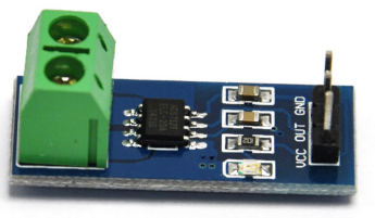
The circuit below was designed using a product called LochMaster.  It is assembled on Radio Shack perfboard.  To the left are the current limiting resistors to control the station lights.  The are heavy duty (1 watt) as there are many LEDs to light for each section.  The resistors at the bottom will control street lights and building lights.  At the top are the inputs from the track and the two blocks that require current detection.  There are inputs for trickle power that will allow for current detection should the main power be shut off.  The current detectors are using the bridge rectifier/optoisolator/555 design.  The downside here is the 1.4 volt drop to the train power.  I supplied an LED for each detector as a troubleshooter in case of any failure.  The detector outputs are fed into the signal controller circuit on the right.  They also have outputs designated DA5-01 and DA5-02.  These signals will be used by neighboring sections.  Also note there are inputs DA4-01 and DA1-07 from neighboring sections.  The outputs to the signal LEDS are shown.  Each has a current limiting resistor and the design uses the common anode technique.


20150228_113832_resized


I considered using Arduino as this would eliminate the controller circuitry, but decided against it since it would be easy to short pins and damage the board.  PCB would be nice, but it is very expensive.  For heavier duty inputs 18 AWG wire is used instead of the 22 AWG.  This is shown here. All bus wire between sections is 12 AWG.


20150228_130003_resized

Attachments

Images (3)
  • Section.05
  • 20150228_113832_resized
  • 20150228_130003_resized
Last edited by Joe P
Original Post

Replies sorted oldest to newest

Arduino would be nice.  For this section I guess the Uno version would suffice.  I would be unable to use my regulated 5 volt DC power for the board because the specs state that it requires between 7 and 12 volts DC.  My controller uses one 7400 quad NAND gate chip and one hex inverter 7400 chip each supplied by 5 volts DC power.  I guess it would not make a difference if I used a different voltage for DC power as the only thing I would need to do is change the values of the current limiting resistors for LEDs.


My worry with Arduino is its durability to withstand the many mistakes made as electronic hobbyists.  I have many times accidentally shorted my DC supply voltage or created solder bridges. Situations like that would play havoc on an Arduino I think.  It is also easy to destroy an IC chip, but they have performed near flawless regardless of the mistakes I make.  If I destroy an Arduino Mega (as some of the more complicated modules would require) I am out $50.

Actually, my first stillborn signal controller was pre-Arduino, but used the same

basic chip: an Atmel ATMega CPU. Easy enough to swap out the controller on the module should it gets zapped. But it's still pretty hard on those chips. But a

replacement CPU for an Arduino module is also cheap: about 3 bucks.


Here is Section 6 on the "A" line.  There are 3 tracks, 2 Local and 1 express.  Each is a block containing a single current detector.


Section.06A


The "B" line has 5 blocks (not shown).  Normally I would construct a single board containing 8 current detectors for the entire section.  However I have single detectors on a Radio Shack dip perfboard that I used on my previous layout.  I have additional additional hardware that I wish to reuse also.  So I constructed a triple current detector accessory board with reused parts.  There is no controller in this circuit, so there are 6 outputs, 3 for the section 6 controller yet to be built (white labels), and 3 of the same outputs (gray labels) for neighboring sections.


20150303_151408_resized

Attachments

Images (2)
  • Section.06A
  • 20150303_151408_resized

Elevated section 6B has 5 current detectors. It is part of a proposed elevated station where detectors DB6-01 and DB6-02 are in the station and DB6-03 is on a layup track. Detectors DB6-04 and DB6-05 are on express tracks on the upper level. So it is a double elevated structure.


Section.06B


The 5 current detectors are constructed by reusing detectors from my previous layout. There are accessories for station, street, and building lighting. All detector outputs are duplicated and used in neighboring sections.


20150407_220606_resized

Attachments

Images (2)
  • Section.06B
  • 20150407_220606_resized

Here is Section 03 of the new layout.  The track design is for BOTH subway and elevated.  The elevated line will have a two tier design (double el) and support part of a station.


Section.03


There will be a 12 block current detector to control the signals (7 subway(A), 5 elevated(B)).  Additional accessory lighting is also supported by the circuit for station lighting, tunnel lights, buildings, and streets. Outputs will also be used by signals in adjoining sections.


20150508_113911_resized

Attachments

Images (2)
  • Section.03
  • 20150508_113911_resized

Well I'm back at building these detectors. I have 123 to build and am nearly done with 95.  The parts list consist of building a basic current detector using an 8-amp bridge rectifier, 120K, 330, and 33 ohm resistors, a 2506 optoisolator, 555 timer, 0.1 micro farad capacitor, 10 micro farad electrolytic capacitor, and a 0.01 micro farad capacitor. The current detector design was derived from this documentation.


http://www.gatewaynmra.org/199...on-systems-circuits/

This is subway Section 1A of the layout. This configuration is quite complex as there are switches to the looped station in Section 5 or the continuous oval.  There is an additional switch to a non-electrified stub end that will be used to add trains to the layout.  Also section 1AB is part of the ramp that will connect the subway section (A) to the elevated section (B).  There are 9 blocks in this section.


Section.01A


This is section 1B which is the elevated portion.  There are 3 blocks.


Section.01B


Section 01 uses a 12 block current detector, one for each block, as well as for accessories such as circuitry for structure, street, and station lighting. Also some outputs are used for neighboring sections.


20151111_210640_resized

20151111_210702_resized


This is subway Section 2A of the layout. Also section 2AB is part of the ramp that will connect the subway section (A) to the elevated section (B).  There are 5 blocks in this section.


Section.02A


This is elevated section 2B of the layout.  There are 4 tracks here where the middle 2 tracks are a ramp to the double elevated section and there are 8 blocks.


Section.02B


Section 02 uses a 13 block current detector, one for each block, as well as for accessories such as circuitry for structure and street lighting. Also some outputs are used for neighboring sections.


20151111_210728_resized

20151111_210749_resized

Attachments

Images (8)
  • Section.01A
  • Section.01B
  • 20151111_210640_resized
  • 20151111_210702_resized
  • Section.02A
  • Section.02B
  • 20151111_210728_resized
  • 20151111_210749_resized

While these designs seem repetitive, they are crucial for my signalling system. These current detectors are of the bridge rectifier variety and will knock down track voltage by 1.4 volts.  This design also accepts a 12VAC trickle voltage which will allow for current detection should there be no transformer power to the rails.  This is designed for conventional mode.


Section 10A is illustrated here.  The design allows for 3 detectors in the subway and 2 more for the ramp to the elevated.


Section.10A


Section 11A is designed with 8 detectors. There are 3 in the tunnel, 3 in the station that straddles Sections 11A ans 12A, and 2 on the ramp to the elevated.


Section.11A


Sections 10B and 11B are the elevated section.  Each section contains 3 detectors and an elevated station straddles both sections.


Section.10-11B


Here is the circuit for Section 10.  These are 2 circuits separated by parts A and B.  The reason for this design is that I decided to reuse components from my old layout.  This is done for Sections 6, 7, and 8 also.  Part A has 5 detectors as well as resistors for tunnel lighting.  Part B has 3 detectors with resistors for station, street, and structure lighting. Detector outputs are also available for neighboring sections.


20151117_120040_resized


The circuit for Section 11 is a combination of both parts A and B.  There are 14 total detectors.  The resistors control lighting for BOTH stations on the elevated and subway portions, tunnel, structure, and street lighting.  Detector outputs are also available for neighboring sections.


20151117_115937_resized

Attachments

Images (6)
  • Section.10A
  • Section.11A
  • Section.10-11B
  • 20151117_120040_resized
  • 20151117_120040_resized
  • 20151117_115937_resized

Joe, For several decades I've had fantastic memories of growing up in Bronx, NY and traveling through all 5 Burroughs by Subway and the elevated sections. I wish you would have done a complete How-to Videos from start to finish. 

Do you think you can start from where you left off to finish the rest of the project in video Please. 

Sincerely 

Allan Martinez 

Note that GRJ is simply referring to the current sensing function of the OP's circuit.

Untitled

From my understanding of the OP's circuit, the eBay current-sensing module replaces the bridge-rectifier.  As OP says, his 8-Amp bridge rectifier drops about 1.4V.  This is quite a burden; in other words if a subway car is pulling, say, 2 Amps, then the current sensor (i.e., the bridge rectifier) is burning 1.4V x 2A = 2.8 Watts!  The eBay module uses a different current sensing technology which burns less than 1% of that (i.e., only milliWatts) and does not impose a 1.4V "tax".

As I understand GRJ's comment, the eBay current sensors would be hooked to a microprocessor (Arduino) which would perform the additional signal-conditioning and timing functions presently performed by the other components of the OP's circuit.

What's nice about the "Hall sensor" sensing technology in the eBay module is it senses both DC and relatively high-frequency AC.  This means it can be used with DC track systems like in HO/G-gauge, 60 Hz AC O-gauge, and high-frequency DCC systems.  The current-transformers (doughnut-type current sensors) used in some O-gauge AC systems cannot sense DC currents and may not adequately sense the high-frequency AC currents in DCC systems.  Obviously an end-user doesn't care about a universal sensing solution - just one that works for the layout at hand - in which case if this is an O-gauge 60 Hz AC system I'd suggest looking at ~$1 eBay current transformer modules which would also burn less than 1% of the power (and no 1.4V voltage-drop tax) relative to the bridge-rectifier sensor...for example eBay 201614919336:

201614919336


Attachments

Images (2)
  • Untitled
  • 201614919336
Last edited by stan2004
christhetrainguy09 posted:

So basically this senses current draw when a loco is near the drop in the track? Gap the center rail and it senses the current draw in that block?

Yes.  What nice about the OP's bridge-rectifier "current sensor" is that it generates a 1.4V (or so) output voltage for a wide-range of currents.  1.4V is plenty of voltage to trigger down-stream circuits for signaling or whatever.  An 8 Amp bridge rectifier is less than 50 cents on eBay:

Untitled

OTOH, the current-sensor in GRJ's eBay module or the current-transformer doughnut sensor generate an output voltage proportional to current flowing in the circuit.  So if your consist consists of un-powered cars, you need to figure out a way to draw current for non-engine rolling stock which do not draw current.  Otherwise you have an occupancy detector that only detects occupancy of current-consumers (engines, lighted cars, etc.).  In HO systems this is routinely done by replacing wheel-axles in non-powered cars with wheel-axles that have a resistor built-in to draw current between the 2 rails! 

This current-sensing approach to occupancy detection is applicable to the OP's layout because it is a subway where consists (typically) have all lighted/powered cars so you are "guaranteed" to draw some current from end-to-end.  As mentioned, in HO you replace insulated axles with ones with a resistor built-in to draw some current.  In O-gauge I suppose you could replace an un-powered wheel truck with a powered wheel truck (i.e, one that has a center-rail roller/pickup) and insert a resistor, lamp, or some other electrical load that draws current.

Attachments

Images (1)
  • Untitled
Last edited by stan2004

Stan thanks, we at the club run a caboose on every train, so i think i have that covered. But i am open to ideas for the non caboose trains.


using GRJ module, simply run track power to one terminal and the power drop to the other terminal and plug the rest of the pins up to Arduino and write a little code and bazinga you have a block detection   

GRJ, i would love to do the isolated blocks but the layout was wired by a wire happy guru 20years ago and grounds are tied together all over the place. Would take too much time to redo the wiring as it stands now. So i created a photocell method works fine at evening times but during the day its haywire (environmental light) o i thought this might be a better solution. 

Well, if you can't do the insulated tracks, the optical solution is the other method that doesn't involve current sensing.  One thing you can do to improve the reliability of optical sensing is to use modulated beams and a smarter detector to sense the beam.  If you simply drive the beam with an 8khz signal, for instance, you can then have the receiver look only for a signal that's modulated at 8khz.  That eliminates the normal issues with stray light triggering the sensor.

christhetrainguy09 posted:

...using GRJ module, simply run track power to one terminal and the power drop to the other terminal and plug the rest of the pins up to Arduino and write a little code and bazinga you have a block detection   

Well, it depends on your definition of "a little code" and your definition of "bazinga"!

The IC sensor in GRJ's module uses the relatively recent ACS712 IC chip manufactured by Allego Microsystems which generates a voltage proportional to sensed current.  The scale for the 20 Amp sensor chip is 100mV per Amp.

Untitled

So even if you have a caboose at the end of every consist, let's say its lamp draws 5 Watts.  At 18V command voltage, that's less than 300 mA (0.3 Amps).  The eBay ACS712 module generates "only" 100mV per Amp...so when the caboose rolls by, the output voltage to the Arduino would be a modest 100mV/Amp x 0.3 Amps = 30 millivolts!  I'm not saying 30mV is difficult to detect but to quote GRJ, no job is easier than the one you imagine someone else doing!!! 

As mentioned, the "beauty" of the bridge-rectifier detector method is that even if the current is "only" 0.3 Amps, the output of the detector will be about 1.4 Volts...or some 50 times greater than the eBay sensor!  In the OP's case, this 1.4 Volts is used to trigger an opto-isolator (which trips at about 1 Volt).

So, as GRJ points out, if you can't or don't want to use the isolated outer-rail method, you need to consider something like an IR/ITAD detector if occupancy detection is the objective.

Attachments

Images (1)
  • Untitled

 In line with the modulated optical sensor method GRJ mentions you can buy an eBay module for about $2 that consists of a modulated/pulsed infrared LED at about 40 kHz and a mating infrared detector.  This way you can operate without issue during the daytime or with bright train room lighting.

modulated IR sender-receiver

IMG_1511

The spectre of replacing un-powered wheel trucks with powered trucks loaded by a light-bulb or resistor or whatever (to create a current load) seems like a non-starter in the O-gauge world.  Again, I think the current sensing approach is fine for the OP's subway application because all cars are lighted and/or motorized and hence draw current.

Attachments

Images (2)
  • IMG_1511
  • modulated IR sender-receiver
Last edited by stan2004

Add Reply

Post

OGR Publishing, Inc., 1310 Eastside Centre Ct, Suite 6, Mountain Home, AR 72653
800-980-OGRR (6477)
www.ogaugerr.com

×
×
×
×
Link copied to your clipboard.
×
×