Hello,

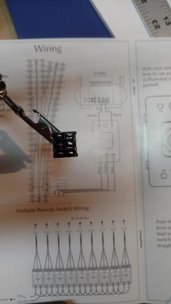
Trying to replace the stock toggle with a DPDT momentary on.  Having trouble figuring out which wire goes where.

Any help is appreciated.  CSX AL recommend these toggles some years ago.  Finally getting around to wire them.  Did some searching but could not find a good graphic.

1481483798664-166235341

Thanks

Ron

Attachments

Images (1)
  • 1481483798664-166235341
Last edited by Ron045
Original Post

Replies sorted oldest to newest

cjack posted:

The two center pins are the poles. The two pins on the end opposite the way the handle is thrown are connected to the poles.


Sorry... Electrical novice here.  So the two middle are for the green and red from the switch?  

We're do the + and - from the power source go?   Do I need to jump the outer pins diagonally?  What about the third wire from the switch? MTH calls it Blue but it is really Black.

Thanks for your patience.

Ron

Oh good. I was just trying to find out how these switches work and find a better picture of the switch wiring diagram. Looks good to me now that I can see it...what's the remote controller for if you are using the switch...or are you replacing the remote controller?

Oh that's what you said, replacing the stock toggle! I should read more...

Last edited by cjack

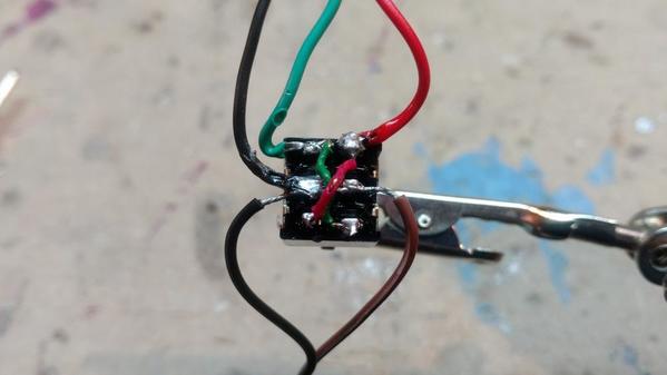
Spent today experimenting.  See picture.  This works, but is it really correct?

Please ignore the sloppy soldering.  I need to buy a pencil tip iron.  This is just a mock up to test wire config.

So from the top.  Green and Red wire from the switch.

From the middle, black wire from the switch and black (-) from power on left, brown (+) on right.

Then jumpered the top left to bottom right and the top right to bottom left.

So is this correct?  Is there a simpler way to do this?  I tested a double switch and it works.  Just seems like a lot of work.

Feedback and thoughts welcome.

Ron

IMG_20161214_165739657

Attachments

Images (1)
  • IMG_20161214_165739657
Last edited by Ron045

I was clearly over thinking this.  When I first read Stan2004's post I somehow though he wanted me to incorporate my momentary switch with the MTH toggle.

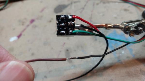
I took a second look after your post CJACK and then realized that I could wire it just like any other switch where the + could go directly to the track switch machine and only the negative would need to go through the momentary toggle.

The pic shows the toggle wired as instructed.  Red and Green to the switch machine.  Black (-) comes from the power source.  The Brown (+) comes from the power source and connects to the Blue (for some reason MTH made it Black) which goes directly to the switch machine bypassing the toggle.

Thanks all for your feedback.

Ron

IMG_20161217_120951678

Attachments

Images (1)
  • IMG_20161217_120951678

So I have the switches working fine.  Starting to build my panel and thought it would be nice to have Red and Green lights above and below the toggle switch to signify the track switch position.  Did some searching, but could not find the answer.

Can I accomplish this with the same toggle?  In my first attempt the light would only stay lit and would turn off when I released the momentary switch, which is logical.  How do I get the light to stay on?

Thanks

Ron

stan2004 posted:
Ron045 posted:
...In my first attempt the light would only stay lit and would turn off when I released the momentary switch, which is logical.  How do I get the light to stay on?
Where did you wire "the light"?   Did you trying wiring up two lights?  One from red-to-black, the other from green-to-black.


Stan,

Assume you mean one light on the Red and Black from the toggle and another from Green and Black on the toggle.  No, I did not do it that way, but will try it.

Thanks

Ron

Add Reply

Post

OGR Publishing, Inc., 1310 Eastside Centre Ct, Suite 6, Mountain Home, AR 72653
800-980-OGRR (6477)
www.ogaugerr.com

×
×
×
×
Link copied to your clipboard.
×
×