The plot thickens...

My layout project moves from planning and benchwork to electrical, and from forum topic to forum topic.  This is where I really need help.  I know nothing about electricity.

I plan to run Lionchief and Lionchief Plus locomotives on my layout.  So track power will need to come from an 18V DC brick or two. 

Having a master ON/OFF switch within easy reach is a must.

I'd like to run 12V DC for accessories.  This layout will have the Lionel track gang, animated billboard, intermodal crane, MTH crossing gate or two, Atlas uncoupling track, and a bunch of LED's.  I'm cornered into using Fastrack switches, as that's the only things I know of that will work off DC.

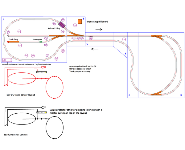
Below I've sketched out where I would like to place animated accessories and model cars with led lights.

LED = model cars

RR = MTH Railking crossing gates 30-11012 (which I haven't bought yet) activated by the outside rail.

D = LED dwarf signals (Not purchased yet.  No idea which ones to get).  I would like to avoid using infrared activation.

S = 3 light block signals (again, not purchased yet, and little idea which one to get), with a facing arrow.  I haven't decided where to place them yet, nor how to separate them into different blocks.  Again, I would like to avoid using infrared activation here as well.

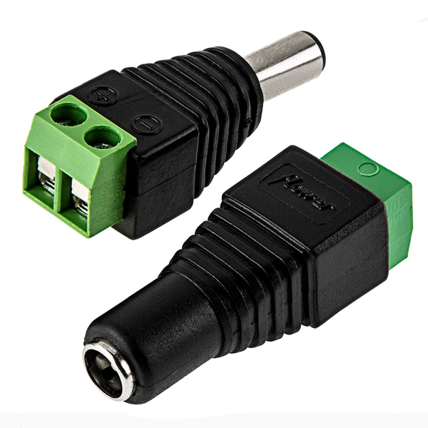
A, B, C, D, E, F, and G are different layout modules I've made for easy transportation in a minivan.  Once this layout is well on it's way, expect to see it at various train shows on the Eastern seaboard.  For easy, fast and reliable connections I was thinking of using these...

standard-barrel-connector-to-screw-terminal-adapter

... 2.5 mm for track power and 2.1 mm for accessory connections.

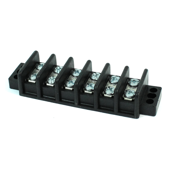
Speaking of connections, these terminal blocks look nice for accessories.  I was thinking of painting the positive power block screws in the same color as the positive wire.

DoubleRow-6Position-Terminal-Block-47356_f

Here's my rough sketch of where track and accessories should go.  Circles on the red and black wire diagrams would be the barrel connectors between each module.

layout 15 -- atlas fastrack switches wiring

I'm using Atlas track, and I plan to drop 18 ga feeders from every section using screws in the track and soldering to 14 ga bus wire under the layout.

I'd like to run two trains at the same time with smoke units on.  The first train is a Hogwarts Express.  The second is the Union Pacific et44ac Lionel will, fingers crossed, deliver by Christmas.

Please help.  How do I wire this layout?

Attachments

Images (3)
  • DoubleRow-6Position-Terminal-Block-47356_f
  • standard-barrel-connector-to-screw-terminal-adapter
  • layout 15 -- atlas fastrack switches wiring
Last edited by Mr. George
Original Post

Replies sorted oldest to newest

Color coding terminals is a good idea, but wire numbering labels are even better. Writing next to terminal block is the common alternate to painting screw heads.

The barrels are ok too.  I prefer other connector types myself, like molex types (customizable multi pin connector systems, Molex is actually just a brand that achieved "Q-tip and Kleenex" recognition over time, there are better, there are worse) which are actually quite common in industrial settings/supply houses.  The reason I like them is you just replace bad pins, vs a whole connector.  Pin positions & plug/socket keyways prevent plugging stuff in wrong. Plus, you can write on most plug/sockets white plastic with a Sharpie marker too. 

They are very hard to crush beyond repair. Thats the weak point of your choice.  Many modular builds just use household ac plugs for connections,  keeping the males short Cheap, fast to  (espplug durableecially heavy duty/industrial grade), available everywhere. Colors and lengths keep mistake at bay.....[ the composer won't let me correct that mess above, I hope you get it ]

Look at lever type splice connectors vs wire nuts or suitcase splicers.

  Double check me here.....It does NOT have to be DC power to the track (LC+ is ac/dc for sure, I think the "command board"  is the only big difference). The DC is just what was supplied new because the low amp wall warts are so cheaply produced. The minimum is about 14v (some lower), the max should be 18v, things start to fry at 20v... (a leway of 2 volts for surges). I'd likely run lower than 18v myself as we have a lot of ups & downs in home supply voltage here. My setting on Monday might be higher or lower than the day before. One day, trains will jump track on full throttle(conventional) the next day I may have to remove cars due to neighborhood power draws making them run slower (I'm in an supply hub too. They use our power when they need some elsewhere. Seldom loose power for more than 5 min... but the power cuts out often as a trade off (once a month or so, 30 sec. to 5 min.)

  If you plan on all dc accessories , beginning with dc makes sense. However, converting AC power to DC is as easy as a bridge rectifier (likely under $5)   The advantage is higher amperage available is usually higher and cheaper in AC transformers.  (Ac item is safe used on Dc, it won't toast them, but they may not work, but usually do. Dc items will usually fry on AC (unless converted to dc) . 

You may only need one AC supply vs half a dozen (?) wall warts as well.

  Since you plan on a set voltage for track, if the extra amps are indeed available, reducing volts to 12v  along an accessory line is pretty simple, a diode will knock voltage down about 0.7v per diode used. Make a chain and measure the voltage drop. (a diode is simply a "one-way check valve". AC would require twice as many, each chain facing opposite directions to handle both directions of AC flow.  If you needed to reverse your DC supply connections (say to run an accessory in reverse) you would also need two chains.  Match the "general purpose diode" amp size to above tranformer amp output; the higher amp the lager it is, and cooler the diode will run.(oh yes, there will be heat, don't touch them until you know how hot... thats the voltage loss in heat.  All that said, from 18v to 12v would take about 10 to 24 diodes total, so another way may be prefered (but it will work fine). But If you can run at 14v that is reduced to just 3 to 8 diodes total 

  DCS prefers a "star" wiring where the power goes to a "center point" and from there drops are split off to the center of blocks of about equal length. (4 blocks in a circle, #1 block, 12 to 3 o clock track, connected at 1.5. Then #2, 3 to 6 o clock, connectected at 4.5, etc. etc. An inner loop could share the same split, two loops block #1 at 12 to 3 on both, #2 at 3 to 6 on both, etc.)

   You should choose wire after you know the max output of your power supply. The wire should handle it easily or be fused. Oversized wire is better than undersized wire. AWG (american wire gauge) is a standard, X amps per Y feet at Z volts, (emphasis is only the amps per foot  for us really)  Charts are easly found on the net.) 

Thank you Adriatic, labeling the wires and terminals is a great idea.  What color wires would you use for the accessory circuit?

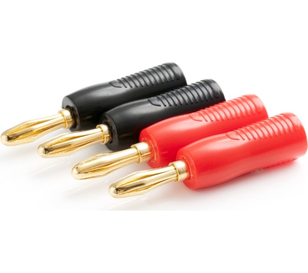
I don't think Molex connectors will survive multiple forced insertions this layout will have to go through, or as the experts call it, "mating cycles."  In cars, connectors usually broke on me after handling no more than half a dozen times after leaving the factory.  Barrel terminals or banana terminals look like they may be a lot more durable.

 u_10166263

For power are you suggesting a Lionel transformer?  Or a bigger AC wall wart?  As for layout control, I don't plan to use DCS.  Lionchief  makes me happy.

How much electricity do trains suck up? 

Looks like swapping incandescent bulbs in Hogwarts Express passenger cars for LED's is not a bad idea either.

BTW, my layout is around 57 feet long, according to SCARM


Attachments

Images (1)
  • u_10166263
Last edited by Mr. George

Add Reply

Post

OGR Publishing, Inc., 1310 Eastside Centre Ct, Suite 6, Mountain Home, AR 72653
800-980-OGRR (6477)
www.ogaugerr.com

×
×
×
×
Link copied to your clipboard.
×
×