Hey guys,
I'm confusing myself at the moment while I install a PS2 BCR.
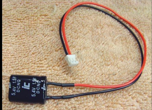
In @gunrunnerjohn s posts, he has a photo of a supercap and mentions to connect the positive lead to the positive wire from the PS2 harness, and includes this photo:
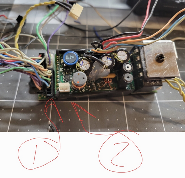
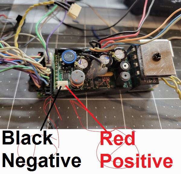
Looks simple enough... But from my harness I've got on my table, the red wire appears to be in the other side of the connector:

The connector is black instead of white, but as far as I can tell they're the same connector series and the retaining flaps (the tiny flaps that lick the crimped ends into the connector) are on the top in both of our pictures.
John, did you switch the red and black wires in your connector?
I suppose the question is really which pin the positive leg of the capacitor needs to connect to in this photo: positive to pin 1 or positive to pin 2?