
This is a Postwar tubular switch track issue. In one location on my layout I have 3 022 switch tracks in a row. Here it is:

20181127_081454

This is at the heart of my interchange and interconnected  layout, where the 2 main lines interconnect and fiber pins are used so I can have 2 independently powered main lines, and also can run a train from one main line to the other. The switch to the far left in the above photo goes to a siding, which is also independently powered with fiber pins.

The problem is that when a Postwar train is over the middle switch, it slows down or sometimes stops because of a big voltage drop.

In the next post below, I will attach videos showing how the train slows down or stops.

I am very interested in your input on how to lessen or eliminate this slowing down or stopping.

Attachments

Images (1)
  • 20181127_081454
Original Post

Replies sorted oldest to newest

In the video below, you will see this Postwar 2 motor Lackawanna FM Trainmaster slow down a lot going left to right, and slowing down a little going right to left:

It makes no sense to me that there would be such a difference related to which direction the train is running.

Those switches are very clean, so dirty track is not the reason for the voltage drop. 

I have a couple of ideas I will share, but will first wait to see what you folks have to say to solve this problem.

This next video shows a Steamer stopping over the middle switch:

Attachments

Videos (2)
20181127_082846
20181127_082342

Arnold, because of all the fibre pins the voltage flow gets compromised at the middle switch.  It may be helpful if that switch remained live at all times.  This can be done by soldering power feeds to the center and outside rails of this switch track.  However, do not solder jumpers to the control rails of the switch track.  

Now, where to get power from for those extra leads.  It could come from another binding post of your ZW transformer, like post C or B.  

Someone smarter than I should check on that.  I'm not certain it would work.

On my small layout, I have avoided using fibre pins on my O22 switch tracks.  Instead I leave a gap on all three rails on the two ends of the wye.  The other end does have pins in order to keep power running through the rails.  In this way, servicing my switch tracks is made simpler.  I simply remove any screws holding them in place and lift the pin-less end slightly and pullout the switch track. 

Hi Arnold, 

Seeing that the trains loses voltage only going in one direction makes me consider you might possibly be losing the ground on the outside rail going that way (the length of the last 2 consecutive switches to the right in the video), and the ground in the other direction is okay.  Just a thought that you might check that first.

You might also double check the soldering joints inside each switch as these can break over time but are a pretty easy fix.   

Last edited by bostonpete

I am guessing that if you lock your steamer in forward and repeat the demonstration it will not stop. 

The next thing I would do is use that gem dandy crimping tool that was being discussed the other day and tighten the pins between the left switch and the center switch as pictured on the screen.

If that solves the problem I would then consider the jumper solution.

Bill DeBrooke posted:

I am guessing that if you lock your steamer in forward and repeat the demonstration it will not stop. 

The next thing I would do is use that gem dandy crimping tool that was being discussed the other day and tighten the pins between the left switch and the center switch as pictured on the screen.

If that solves the problem I would then consider the jumper solution.

Bill, you are correct about the train running much better in the forward only position. Will try out your ideas later. Thanks.

Dan Padova posted:
Arnold D. Cribari posted:

What if I added a very short piece of tubular track between 2 of the switches and put a lock on there to add a power feed?

I think that's a capital idea, Arnold.  

No need to add track sections - you can use the center terminal on the switch machine to feed the outer rail and use the aforementioned barrel plugs to feed the center rail.

bmoran4 posted:

I would make use of properly sized barrel plugs to feed the center rail of the O22 switches. TinMan sells them:


http://www.tinman3rail.com/?pr...old-style-bootstraps


You may want to check the spacing of the pick-up rollers on the unit and see if that distance is the same as the two dead spots associated with the two back-to- back switches.  The engine/consist speed, allows the train to continue through the switch(es) but the engine lights dim (or go out) which indicates loss of power. 

This Atlas switch dead spot is about 1.5" (1" to 2.5" marks) .  Power would be supplied by the other pick-up roller, unless it also is on a dead spot.  Some of may newer Atlas models have (4) pick-up rollers. 

The position of (2) dead spots, on two back-to-back switches, was the same distance as the pick-up roller spacing on this Weaver E8 model.  The unit would stop. 

Last edited by Mike CT

I agree with making sure the track pins are all crimped, adding jumper wires between center posts of the switch machine, and measuring to see if the pickup rollers are just the wrong distance apart.

Just to further expand upon BMORAN4's suggestion of substituting the barrel plugs for the original fixed voltage plug.  The outside of the barrel will carry track voltage to the spring contact which will flow directly to the center rail of all points of the track.  It essentially makes the 022 switch an additional lock-on.  The center of the plug will still power the fixed voltage separately to operate the switch independent of track voltage.  Below I have circled the spring contact/booster pin so you can see the flow of power through the pictorial wiring diagram.


Attachments

Images (1)
  • mceclip0
Last edited by JD2035RR
NOT LionelLLC posted:

What's a "bootstrap plug"?  Never heard of it and neither has Google.

Do you mean the fixed voltage plug?

Stu

Stu, I was using the nomenclature used by TinMan on his website.  I edited my post above to avoid any confusion.  Good catch.

FWIW, I ordered my barrel plugs from TinMan yesterday and very promptly received messages that my order was processed and shipped - same day!

bmoran4 posted:
Dan Padova posted:
Arnold D. Cribari posted:

What if I added a very short piece of tubular track between 2 of the switches and put a lock on there to add a power feed?

I think that's a capital idea, Arnold.  

No need to add track sections - you can use the center terminal on the switch machine to feed the outer rail and use the aforementioned barrel plugs to feed the center rail.

bmoran4 posted:

I would make use of properly sized barrel plugs to feed the center rail of the O22 switches. TinMan sells them:


http://www.tinman3rail.com/?pr...old-style-bootstraps


That's an even better idea !

Just want to thank you all for your advice in the above replies, and to share with you the good news that the problem is solved.

It turns out that BostonPete made the correct diagnosis. This was also confirmed by an article in the September 2014 issue of CTT magazine in Questions-Answers on page 19: Dead Postwar Lionel 022 Derailers, Pin Placement Can Kill a Ground.

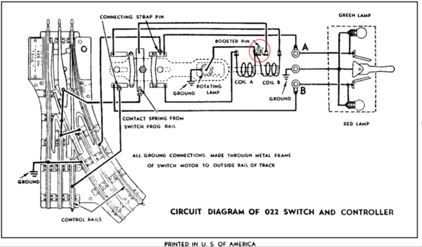
The upshot is that there were fiber pins on both outside rails between 2 of the 022 switch tracks causing loss of a ground and a resulting voltage drop. This, in turn, caused the train to substantially slow down, especially going in one direction through the switches.

I solved the problem by removing the 1st switch on the far left side, which only caused repositioning a siding. The series of interconnecting switches between the 2 main lines (the heart of my long and narrow switching layout) remains undisturbed. Therefore, this solution only caused a small mess, not a big mess, on my layout.

I share this, not only to report the good news for me, but also to help those with Postwar switch tracks to know the importance of the proper placement of fiber pins so as not to lose the ground, and avoid a voltage drop.  Also, the technical information we get from our model train magazines and this Forum is extremely helpful.

My elation in solving this problem is because before today  I have had this voltage drop on my layout for about 25 years!

Some of the other possible solutions that appear in the above replies (which are more sophisticated than what I did) may have also worked, and might have enabled me to keep all the switch tracks and their fiber pins in the same position.

Arnold


bostonpete posted:

Happy New Year Arnold!  Glad things worked out for you.  I will say postwar 022 switches are pretty bullet proof and I would never give them up.  Of course I'm a traditional hobbyist so take that with a grain salt. 

I always appreciate your contributions to the forum and I enjoy your layout videos.

Cheers

Pete

Thank you, Pete, for your kind words.

Although I like a lot of things about both modern and Postwar, I agree with you about never giving up the Lionel O22 switches. I love everything about them. Arnold

At a further follow up, I have largely completed the repositioning of one O22 switch track and moved a siding. Below are short videos of a Williams diesel pulling passenger cars through the consecutive 022 switches in each direction:

Now, there is no loss of a ground in any of the switches, no voltage drop, and the train runs smoothly in both directions.

Total Victory! LOL, Arnold

Attachments

Videos (2)
20190106_083255
20190106_083238

Add Reply

Post

OGR Publishing, Inc., 1310 Eastside Centre Ct, Suite 6, Mountain Home, AR 72653
800-980-OGRR (6477)
www.ogaugerr.com

×
×
×
×
Link copied to your clipboard.
×
×