Originally Posted by gunrunnerjohn:

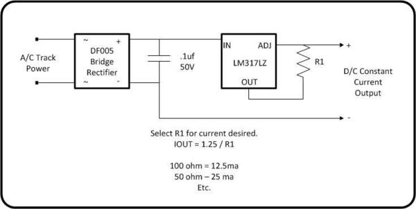
My schematic worked, so as long as you have the pins right on the LM317, it should work.  I hope the Plus side of the bridge is connected to the positive terminal of the cap!

That's why I bought two


All kidding aside, the positive output of the bridge is connected to the longer lead, opposite the side marked with an "-".


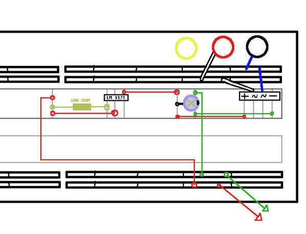
As for the LM317, I'm reading the pins left to right, positive-from-bridge to #1, resistor to #2, and #3 is tied to the end of the resistor before heading to the output connector.


--PCJ

Facing the front of the regulator, from left to right, it's as follows.


Left: Adjustment terminal

Center: Output terminal

Right: Input terminal


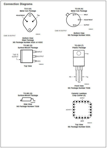
It sounds like you have it backwards, the input from the bridge should go into the input terminal.  Here's the picture from the data sheet, this is looking at the front of the part.


317t

Attachments

Images (1)
  • 317t

I picked up a long roll of this light strip while on a visit to the local electrical shop.


I have 18.7 volts AC on the rails for DCS/TMCC constant voltage.

Running through a full wave bridge rectifier I come out at 18 volts DC.


If I cut the light strips to wire in series will this not give me 9 volts DC per light strip??

For passenger car lighting??

At 9 volts they have a nice glow not to bright??.


Originally Posted by kj356:

I picked up a long roll of this light strip while on a visit to the local electrical shop.


I have 18.7 volts AC on the rails for DCS/TMCC constant voltage.

Running through a full wave bridge rectifier I come out at 18 volts DC.


If I cut the light strips to wire in series will this not give me 9 volts DC per light strip??

For passenger car lighting??

At 9 volts they have a nice glow not to bright??.


You can do that, I prefer to control the current with a constant current source.  If you use the LM117, you can adjust the brightness, a nice feature.  For me, 9 volts DC on the strip was way too bright!

Originally Posted by RailRide:

All I need is a decent multimeter. Got a recommendation


Should I be able to light up a carbody's worth of LED strip (or the whole string?) with this as-is and determine from the brightness whether any further adjustments are needed?


---PCJ

The whole strip will take several amps, so you probably won't be able to light all of those.  Cut out what you're putting in one car and light those.

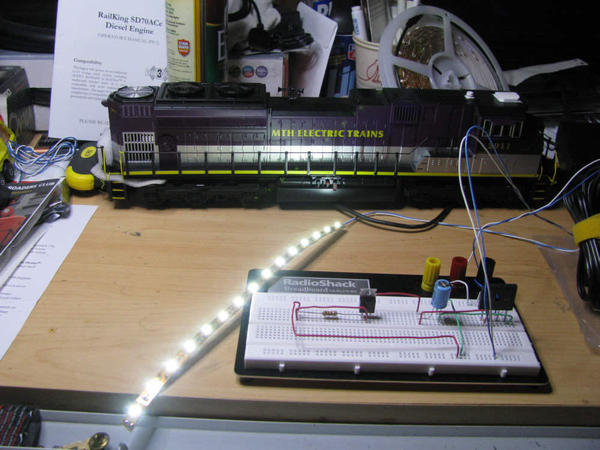
Well, it certainly works

(Bonus: the cap didn't go PAF! when I hooked it to the unfiltered Z-brick)
LEDckt-test04
By the way, that's on the minimum output of a Z-1000 with the controller attached. If I crank it up, it gets a little brighter, but even as is, (and as predicted, I might add) it's a bit on the "needs welding goggles" side of the brightness scale. Now, let's bring on the adjustments  

Attachments

Images (1)
  • LEDckt-test04

The LM317L(anything) is a 100ma maximum current part in a TO-92 package, looks like a plastic transistor.


The LM317T is a TO-220 package looks like one of the large power driver Triac or FET packages on the motor driver boards.  These are rated at 1A or 1.5A, depending on who makes it.


The LM317K is a TO-3 round power package with two ears for screws, it handles 3A.


A plain LM317 doesn't really exist, they normally have a package type specified.  Here's the sheet with many of the types.

lm317

Attachments

Images (1)
  • lm317

One other wrinkle:

I bought some other resistors to experiment. Right now I have a 330 ohm ( 1/2 watt) resistor on the "ADJ" lead of the LM317T. As before I have bright lighting at the minimum output of the Z-1000 (somewhat like really strong fluorescent bulbs). It can run like this for more than an hour and no component is more than slightly warm, if at all. If I turn the Z1000 controller up, the string gets significantly brighter, up to about 1/4 of the controller's travel. At that point the LED string stops getting brighter, but the LED's start getting really warm in a matter of seconds. This...doesn't seem quite right.


---PCJ

Originally Posted by kj356:

Running through a full wave bridge rectifier I come out at 18 volts DC.


If I cut the light strips to wire in series will this not give me 9 volts DC per light strip??

For passenger car lighting??

At 9 volts they have a nice glow not to bright??.

If each strip-of-3 is electrically identical, then the voltage will divide equally to 9V each. In reality, they vary slightly so you might get 9.1V on one and 8.9V on another.  On another pair they might be 9.0V and 9.0V.  


Refer to the plot in my 3/28 post which shows LED current vs. applied voltage. LED brightness as measured in, say, lumens is exactly proportional to LED current. Half the current is half the light output. As shown for one measured strip-of-3, at 9VDC the strip current was 2.5mA. I think this might be a bit on the low side but you need to decide that. 


Note how the current does not vary much between 9.1V and 8.9V. So you won't be able to perceive the strip-to-strip imbalance in the above example.


I used a 5-foot and a 6-foot section of the 300-LED reel to illuminate the subway shopping center I added recently. I power them with 12CDV.


The 5-foot section is behind the store fronts and shines through the cut-outs in the foam-core board I used for the store fronts. The store fronts themselves are Google images printed on regular paper and glued to the foam-core board.


The 6-foot section is in front and over the stores and illuminates the walkway and the shoppers. The problem was that the outer 6-foot section was so bright that it overwhelmed the shine-through store front effect. To make these outer LED's dimmer, I added four 1N4002 diodes (had them already) in series with the power lead to the 6-foot section, and this did the trick. (BTW, I tried 1, 2, 3 4, and 5 diodes and 4 worked best.)


Results (click image to enlarge):


HPM Shoppers SWCar med crp DSC_0539


Alex

Attachments

Images (1)
  • HPM Shoppers SWCar med crp DSC_0539

I'm also into g gauge and have some very power hungry passenger trains..like 20+ amps per train. Each car has 14 incandescent bulbs in it and takes 1 amp to power them.

Switching over to these Led's look like the way to go.

What I do is buy these buck converters on ebay and that way I can adjust the voltage out..that way it won't matter if I'm running on a 20 volt display layout or my at home 24-30 volt layout.

 And I'm lazy when it comes to building circuits as I like things modular. I'll start with some inductors as I'm a DCS guy, bridge rectifier with some 4700uF caps across the outputs to control flicker straight into a buck converter then out to the lights..simple quick and easy! Forgot that I'll install some poly-fuses incase something shorts out internally.


Here's the Buck's on ebay..maybe folks on here could use them as they only measure about 1-1/2" square?

U:US:1123">http://cgi.ebay.com/ws/eBayISAPI.dll?ViewItem&item=170792570361&ssPageName=ADME:LU:US:1123

Originally Posted by CRH:
I'm also into g gauge and have some very power hungry passenger trains..like 20+ amps per train. Each car has 14 incandescent bulbs in it and takes 1 amp to power them.
Switching over to these Led's look like the way to go.

Wow, I don't think even Tommy Z has managed to pull that many amps (although come to think of it, I don't think I've seen him run passenger equipment). What kind of passenger consists are you running?

---PCJ

The LM317T would probably be my choice.  For 12 LED's, the maximum current would be 80ma at full current for the three LED groups on a strip, no HS required for the LM317T.  The CL2N3 only handles 20ma, so you'd have to parallel them for more current.  They also have a much more limited power dissipation in the TO-92 package, so at a high input voltage you may need a clip-on HS.  It's all about the voltage drop across the CL2 and what current is being supplied.

Originally Posted by RailRide:
(one thing I don't think I got answered is, does the wattage ratings matter on the resistor? The one linked above is 1-watt (I backed off the resistance slightly))

In your LM317T configuration, the voltage across the resistor is 1.25V.  Since Power = V x V / R, the power for a 330 ohm resistor is only 0.005 Watts.  The SMT resistor suggested earlier has a rating of 0.125 Watts.  You don't need a 1 Watt resistor there.  Also, the resistor is a 0805 type which is 0.08" x 0.05 inches.  I suggest 0805 because the leads between the LM317T are exactly 0.1".  So as the photo shows, the 0.08" length of an 0805 resistor makes for a tidy assembly job.


If the inductor is the only thing you're ordering from All, then consider this 17 cent inductor from DigiKey.  If you do eBay, I recall another thread on an LED conversion asking about inductor specs and he ended up getting them for IIRC 5 or 10 cents each in small quantity (free shipping but delay from Asia).


If you plan to do more electronics tinkering, considering the $9 shipping charge, Future has some nice pricing on semiconductors if you can navigate their site.  For example, the 1N400x diodes for 2 cents in small quantity. Or the 555 timer chip for 15 cents in small quantity.  I'd say these are in the top few parts that come up this forum.


Post

OGR Publishing, Inc., 1310 Eastside Centre Ct, Suite 6, Mountain Home, AR 72653
800-980-OGRR (6477)
www.ogaugerr.com

×
×
×
×
Link copied to your clipboard.
×
×