
Phil, the culprit is not the Z4000, but the Phil.  When you drastically reduce voltage in a TIU variable circuit, wave forms change and then unexpected things happen, which vary depending on the loco.  Could be whistles, no slow speed capability, or other matters.  If you feed 22 volts in and want to make a Docksider crawl, good luck!

Without going through Barry's book, I don't think he said to open the Z4000s all the way, unless you want reasonable accuracy in the remote voltage readout.  And why is that necessary?  When running conventional, don't you just adjust voltage to attain desired speed?

I stand by my position that the Z4000 does not chop the sine wave. Instead, it builds a sine wave by way of a chopping circuit. Note, that this is the first time that I have used the term chopping circuit. Also in referring to the Z4000 as an electronic power supply, I said "much like a UPS". There is no comparison between the complexity of the circuitry in a UPS and the power circuit in a TIU. The OP asked, how can the Z4000 vary the voltage and I answered. My use of the word "chop" applies to what the output waveform looks like, not how the circuits function.

phil gresho posted:
...

1.  The small HO club I belong to decided to let me upgrade their small 3-rail layout from a Z4000 wired directly to the track  [i.e., conventional control only] to simple command control via a TIU and a DCS remote.  I added a TIU and wired the two Z4000 outputs to the two TIU Variable channel's inputs;  then from the 2 TIU outputs to 2 centrally-placed terminal boards and from there to the several track sections/blocks.  There are 2 independent loops of track;  no turnouts connect them.  Baby simple.

2.  Following Barry's book,  I set the Z4000 handles to 'wide-open'.  Then,  when controlling speed via the thumb wheel, some engines ran with the whistle ALWAYS ON....once the indicated voltage on the remote reached 14 or so.

3.  If the Z4000 voltage was reduced to ~ 16 volts or less, the whistle-blowing stopped.

4. Now for the 'kicker':  While operating both loops via the remote,  I discovered that when the Z4000's output, on either handle, reached ~ 18 or 19 volts, with the other fixed at 14 -16 volts,the whistles on BOTH locos turned on!  Reducing the voltage stopped the noise.

I suspect, but have no way to prove, that the Z4000 itself is the culprit.....Somehow there seems to be some internal, and spurious,  'cross-talk'.

...

1. So to be clear you are operating all engines using conventional voltage mode and by command control you mean you can control the throttle/whistle/bell via a DCS remote?  Or do you intend to operate engines in DCS command mode on these particular loops?

2,3,4.  You say some engines exhibit the spurious whistle behavior.  What type of electronics is in the engines and do you know for sure that they "play well" with the type of waveform generated by the TIU variable channels (chopped)?   That is, if up till now you have only used a "modern" Z4000 to control these engines, how do you know they wouldn't exhibit similar whistle behavior with a "classic" chopped power supply?  Seems I've seen tables of recommended and not-recommended train controllers for a given type of engine electronics.

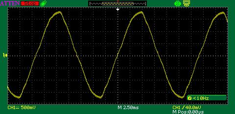
Or, if you can get beyond the side-show of what is and isn't "chopped" I think no one is offended if I claim there are different chopping methods which yield different results.  Even for "classic" chopped supplies, the shape of the waveform for the same output voltage can be different depending on the underlying method.  The Z4000 output is very good though not as "pure" as a straight AC transformer brick.  To that end, when you additionally "chop" a Z4000 with a TIU variable channel it stands to reason that the final output will be slightly different than if the TIU variable channel was fed with a "pure" sinewave transformer.  Additionally, I haven't looked at the TIU variable output recently, but depending on how a "classic" chopped supply performs the chopping, the voltage level going in can affect the shape of the signal going out.  In other words, for the same setting, changing the input voltage (say, cutting it in half) can change the shape of the output voltage beyond simply half the size.  This may (or not) be a factor in why your results vary with voltage going into the TIU.  That is, whistle detector circuits essentially look for a variation in the shape of the AC voltage.

As to whether this makes the Z4000 the culprit is a matter of opinion.

Something simple to try wrt the spurious whistles: put a lighted (incandescent bulb, not LED) passenger car or two on the track. A loose 14V (or so) bulb or two across the track if you don't have a lighted car. 

I'm not commenting on the TIU variable output specifically but some "classic" chopping circuits behave better in the presence of certain kinds of loads.  


stan:  I'm sorry, but I didn't pay close attention.  They are not my engines & the owner was absent during these tests.  All I can say is that some are 'older' [not TMCC] Lionel & some are MTH;  whether Proto 1 or 2 I can't say.

What I DO recall is the case where my own DCS Proto 3 was on the inside loop and one the others was on the outside loop.  Both were running fine with the 2 Z4000 handles at ~ 15 volts.  BUT, when 1 of the handles was increased to, say, 19 volts, BOTH whistles/horns turned on...

The saga continues....Today I replaced the Z4000 by a Lionel PW ZW.

GOOD result:  The problem of spurious whistle blows is gone.

BAD result: Track 2, powered via the left handle of the ZW or the MTH remote, still has a problem:  Blowing the whistle on the Track 2 engine, via either the ZW or the remote,  blows the whistle on both tracks.  

     Since the Z4000 is out of the loop, and since even the whistle controller on the ZW causes both whistles to blow,  the next suspected culprit is the [used; condition unknown] TIU that I used.  Tomorrow I shall replace the TIU and repeat the test program....retaining the ZW for power.

Problem solved!!  From GUNNRUNNERJOHN:   "Another thing that tames the beast is a 10uf non-polarized cap across the tracks, it apparently rounds the chopped waveform just enough to prevent the false triggering."

THANK YOU GRJ; AND STAN.  Installation of the capacitors,  via banana plugs across the 2 Z-4000 outputs, has cured ALL ILLS.  I can even set the handles at 22 VAC or more,  with no spurious whistle.

One last point:  The remote will not blow the whistle when set at MAX [22 VAC].  Back it off 1 click to 21.5 and all is well.  [I've been told that this is normal.]

My plan,  which I shall put into s short OPERATIONS MANUAL for the club members, will be to set the Z-4000 handles to 18VAC before using the remote for speed control.

          Thx again, to all who contributed.


I don't think it makes much difference if the cap is across the transformer or at the track.  However, I suspect it might be a bit more effective at the track where it has the impedance of the leads from the transformer to work with.

Phil, the no whistle or bell at full throttle is normal.  The controller needs some headroom to impart the DC offset, at full throttle it has nothing more to give.

Last edited by gunrunnerjohn
gunrunnerjohn posted:

I don't think it makes much difference if the cap is across the transformer or at the track.  However, I suspect it might be a bit more effective at the track where it has the impedance of the leads from the transformer to work with.

Are we talking about the same thing?  As I understand it, Phil placed the cap at the Z-4000 output which is the INPUT to the TIU variable channel.  Placing the cap on the track (as I interpret your original suggestion) is the TIU variable channel OUTPUT.

I think the effect of filtering the Z-4000's relatively clean sinewave-like output is materially different than filtering the TIU variable channel's chopped sinewave output.  Or at least much more different than the effect of the cap at the TIU variable banana outputs vs. the cap at the track (with the additional impedance from the leads).

I had the same thought later that night; i.e., WHY did I put the caps @ the Z-4000 output, rather than @ the TIU output?  I have 2 answers:

1.  I was not thinking clearly. 

2.  I was prescient!

Fortunately, as I used banana plugs, I can easily make the swap....and will,  just to see if there's a difference.  BUT,  why knock success?

phil gresho posted:

Fortunately, as I used banana plugs, I can easily make the swap....and will,  just to see if there's a difference.  BUT,  why knock success?

Because inquiring minds want to know!  It's also curious to me that placing the cap at the Variable Input helps.  While you are running conventional mode on your Variable channels, placing a cap right on the track has the annoying behavior of degrading the DCS command signal.  So for some it could be a bother to remove/install that cap if alternating between command/conventional on a Variable output.

phil gresho posted:

That's the easy part.  What about the TRANSIENT that occurs just after t = 0 in your graph?  I.e.; the INITIATION of the offset.  [That's where high-frequencies occur....]

That transient would happen with any transformer, probably more abrupt with an old PW model.  When they do this offset, it's with physical switch contacts, not electronically generated.

gunrunnerjohn posted:

The DC offset is just that, it's a shift in the zero voltage reference point.  The blue represents a pure AC waveform with no DC component, the green represents the AC waveform with a 3V DC offset.

But are you sure this is how the TIU variable channel creates DC offset?  With chopped controllers it is common practice to turn the switching device (transistors) "ON" longer during the positive half-cycle of the 60 Hz signal.  And for the Bell to turn the switching device "ON" longer during the negative half-cycle.  Thus, the DC offset is not a wholesale baseline shift up or down but rather fatter looking pulses on the positive of negative portions of the waveform.  This averages to an effective DC offsets and hence there are filters (capacitors) in the offset detection circuitry in the engine to smooth out this "chopped DC".

I'm beginning to think that TO REALLY UNDERSTAND this,  we need the details [wherein the devil resides] of just HOW the Z-4000 're-creates' what looks like a 'smooth' sine wave.....

We may need the help of a true electronics engineer;  one who knows both the electronics and the mathematics.  [I'm a 'mathematical' engineer; not an electronics guy....]

Last edited by phil gresho
gunrunnerjohn posted:

Stan, I was just trying to explain the concept. 

I believe you are correct as to the TIU's method.  That's also why the TIU can't do the offset when you're at full throttle, it doesn't have any more "fat" on either side of the waveform to generate the offset.

Of course we're just jawboning on details here, but Phil did say that if he backs down from 22V to 21.5V the whistle starts working again.  It's hard to believe this provides enough head room (or voltage fat) to provide the several volts of DC to trigger a whistle detector circuit?!  A true mathematical engineer could tell us what this effective offset voltage would be!

Of course another "test" would be to put only 18V AC into a variable channel, set the throttle to max and see if the whistle can be fired.  It is also possible that the circuit could chop out part of the negative half-cycle to create a positive DC offset.  Seems there are anecdotes on how an engine slows down or speeds up when the whistle or bell button is pressed in conventional operation which is another tangent to the discussion. 

phil gresho posted:

Stan:  Re: your statement,  " This averages to an effective DC offsets and hence there are filters (capacitors) in the offset detection circuitry IN THE ENGINE to smooth out this "chopped DC":

What about 'old'/conventional engines?

If by "old" you mean one that uses some type of electro-mechanical mechanism to detect the presence of a DC offset, then I'd think they might vibrate, buzz or loudly protest to pulsed asymmetrical bipolar pulses.  Or, if designed with chopped controllers in mind, I'd think they could be made to simply not respond using some type of mechanical hysteresis.

The creation of the sine wave with the Z4000 is simply dividing the output into finer slices.  Many years ago I had to synthesize a 400hz sine wave for an aerospace application.  The tricky part was I had to vary it's phase in relation to an incoming power signal.  The method is fairly simple.

Detect the zero crossing of the reference sine wave.

Using a table of values representing the sine wave shape, output them to a bi-polar DAC to generate each step.  The amount of time between steps determines the number of samples that make up the sine wave output waveform.  In my case, I had 2.5ms to output a complete waveform.  Using a dedicated uP, I simply indexed through the table and output the table value to the DAC.  The timing of the slices was fixed by the processing loop at 10 microseconds, so the output waveform had 250 steps or slices.  For a 60hz waveform, it's less time critical to generate a decent waveform.  You can see the steps in this Z-4000 screen shot if you look close.

Attachments

Images (1)
  • blobid0
stan2004 posted:

Of course another "test" would be to put only 18V AC into a variable channel, set the throttle to max and see if the whistle can be fired.  It is also possible that the circuit could chop out part of the negative half-cycle to create a positive DC offset.  Seems there are anecdotes on how an engine slows down or speeds up when the whistle or bell button is pressed in conventional operation which is another tangent to the discussion. 

I've done that test, I run here with a PH180 through the TIU.  At full throttle of the variable channels, I can't get the whistle or bell to function, I have to drop it down to about 20 indicated volts for it to function.

stan2004 posted:
gunrunnerjohn posted:

Stan, I was just trying to explain the concept. 

I believe you are correct as to the TIU's method.  That's also why the TIU can't do the offset when you're at full throttle, it doesn't have any more "fat" on either side of the waveform to generate the offset.

Of course we're just jawboning on details here, but Phil did say that if he backs down from 22V to 21.5V the whistle starts working again.  It's hard to believe this provides enough head room (or voltage fat) to provide the several volts of DC to trigger a whistle detector circuit?

Well, in the world of sine waves and RMS, a DC component adds as just another component. So, say you had a 21.5 volt signal and a 2 volt offset, (2**2) + (21.5**2) = 466.25, sqrt = 21.59. So adding a 2 volt DC offset to a 21.5 volt signal gives an RMS increase of only .09 volts!

The DC component adds to the AC on one polarity, but subtracts on the other! Then too, (ducking as I ask this) what kind of meter are we using to measure the voltages? No response needed, but you get my point.

Add Reply

Post
The DCS Forum is sponsored by

OGR Publishing, Inc., 1310 Eastside Centre Ct, Suite 6, Mountain Home, AR 72653
800-980-OGRR (6477)
www.ogaugerr.com

×
×
×
×
Link copied to your clipboard.
×
×