Still trying to match speeds between 2 transfer tables. Found a description in one of my repair manuals where Lionel anticipated this problem when using transfer tables in tandem. Their solution is to install 3 ohm 10watt variable resistor in series in the black and yellow leads to the faster table to permit adjusting the voltage down to match the other table. Having trouble finding these resisters. Any ideas?
Replies sorted oldest to newest
From my experience with fan restorations, you can get an adjustable resistor, or "potentiometer" or "rheostat" here:
http://www.digikey.ca/product-...ower-resistor/262971
They carry all sorts of stuff like that and you might even have luck just going to your local Radio Shack!
I am with Dale, use diodes. Much less expensive and not subject to variations in load.
Pete
If you're trying to speed match, diodes may not yield the small speed differences needed.
If you're trying to speed match, diodes may not yield the small speed differences needed.
not only that, but as the parts age, i can see this adjustment needing to be tweaked every so often.
The diode string is adjustable in .6-.7 volt increments. Voltage drop will be fairly constant. The resistor will work according to Ohms law and drop will vary as the motor heats up.
Dale H
Taylor if Lionel says to install a 3 OHM 10 w VARIABLE RESISTOR here's what you need. It's actually a 25 watt resistor but that won't matter as long as it's 3 ohm. Hope this answers your question more directly.
On a variable resistor that is rated at 3 ohms, what is that? Is 3 ohms the maximum resistance, the mid range, or what? if it is the maximum resistance, it is not much resistance to control the speed on a Lionel accessory.
Can be adjusted from very little to 3 ohms. However when going toward the bottom of the range you have to be careful of the wattage. A 25 watt 3 ohm wirewound resistor set at half of it's range becomes a 1.5 ohm 12.5 watt one,since only half of it is used for example. Set at 1 ohm it becomes an 8 watt resistor. So range is important when using this in power applications. However I doubt if the transfer table uses too much for this to be an issue.
You could center tap it but still you can not turn it down too far.
The diode string does not have this problem if the amp rating is enough and they are mounted where they can breath. For the accessory mentioned 3 amp diodes may be enough.
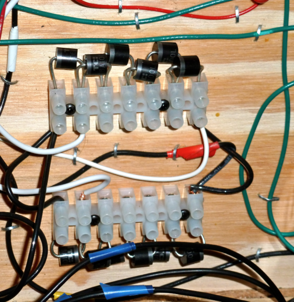
Here is a dropper used as an external bell or whistle controller made out of 6 amp diodes ,mounted on a euro style barrier strip. During operation they get pretty warm but I have not had burnouts.
Dale H
Attachments
Thanks to all for the recommendations. I may wind up using one or more of them, but for now, I am determined to make some use of the Accessory voltage controller. I never got a reply to my e-mail to Lionel, but I did manage to get the service department on the phone today. The tech I spoke to did his best, but the fact is, there is no one there who has any knowledge of the workings of this Lionel product.
I am trying to get it installed and see if I can get some use out it. Right now, I am trying to figure out why the instructions for fine tuning a voltage say to press AUX,AUX2, enter a number from 0to9 and press set on the Cab1 to store the voltage. Sounds a little like storing the momentum setting for an engine, but I don't recall a process requiring pressing both AUX1 and AUX2. Has anybody encountered this key sequence? I also plan to try to track down Lou Kovak, the
designer of most of the TMCC control devices, probably including the AVC. Anybody know how to contact him?
Ordered the variable resistors from DigiKey. Installed one in the black and one in the yellow lead to the transfer table to reduce speed in both directions. As far as I can tell there was not enough difference in the table speed to be noticeable. I tied each lead from the table controller to one end of the resistor, set the moveable contact as far from that end as possible and attached the lead to the table to the moveable contact. Am I doing something wrong? Before installing the resistors in the table wiring, I hooked one up in series with the hot lead from my bench transformer to my test track. With a heavily lighted caboose on the track as a load, I got a little less than 1 volt reduction 18.5 to 17.6 volts. Should I be able to reduce the voltage further with these resistors?
Current = Voltage / Resistance. Ohm's Law. So if your 3 ohm resistor drops 1 Volt, the current is 1/3 Amp.
Power = Voltage * Current. So if the current into the caboose is 1/3 Amp and the track voltage is 18V (or so), that's 6 Watts of power which I wouldn't call "heavily" loaded but enough to brightly light a caboose.
Since it appears you have a meter, I suggest you measure the AC voltage across the resistor when driving the table. This gets you a nominal current to operate the table. With your AVC or another controller you should be able to experiment with how much voltage adjustment you need to trim the speeds by directly driving the table and measuring the voltage. I'd guess you're looking for a trim/adjustment range of only, say, 1 Volt or so. Once you know the nominal operating current and required trim voltage range, the resistance to effect this is per the first equation re-arranged or:
Resistance = Voltage / Current.
Why are you running this off track power? Why not just use an accessory tap? Most likely the 3 ohm resistor recommendation was for 12-14 volts in.
Dale H
I have given up trying to match speeds of 2 transfer tables. I tried diodes, variable resistors, pots, and an AMC. All failed. I now have both controlers mounted side by side. When the faster table starts to pull ahead, I release the travel switch for that table for a couple of seconds and then proceed. doesn't really take much practice. I have the red leads from both tables tied together so pressing either table track button powers both tracks. I have installed the AVC I bought years ago to power the tables and all 8 table stub sidings. Each siding gets power thru a single pole double throw center off toggle switch I have the AVC programmed as track 4. ( My 3 TPCs are tracks 1,2,and3. ) Because different conventional engines require significantly different voltages to move at a reasonable and constant speed across the tables and onto or off of a siding, the avc is not programed for a preset voltage. Calling up track 4 makes18 volts from a zw available. I turn up the voltage with the cab1 to get what I want. I usually use 15 volts to move the tables. I than drop the voltage to 12 or so and turn on the toggle for the siding I am moving an engine from to the table or from the table to that siding. I than increase the voltage to a good level for that engine. The upside 0f the system is I have very accurate control of the engine from siding, across table, and onto siding or mainline connector. The down side is I have to use the toggle to cycle the e-unit. Of course, these directions only apply to conventional engines. With TMCC engines,
I dial up full power and control all engine movement with the Cab1.
I'm sorry this got so lengthy, but I wanted everyone who tried to help me to know that I appreciate all the advice, and that I have developed a workable solution.
I am still confused as to why the transfer table motors have to run off track power. If you run the motors from a separate tap you should get them to run at similar speeds.
Dale H
They have never been on track power. THE power source for each table has always
been a dedicated transformer throttle. The reason I have not had the tables on separate throttles has been the additional problem of matching voltage to the table tracks and controlling the voltage to the 8 spurs.
Is there some way to connect the two tables together mechanically? If these are DC motors, connect the two tables(temporarily/semi-permanently) and use one controller, wire the DC motors in series, and they will not fight each other.
If both motors run off one tap at a fixed voltage,add the diodes in series to the fast one until it slows down to the speed of the slow one. You should be able to get it pretty close.
Dale H
If I have both tables powered by a single tap and I lower the voltage to one table with diodes, what happens if I need to lower the voltage from the source to suit a specific engine. Will the voltage to each table be reduced by an equal amount or will the diodes reduce the voltage more if the input is lower?
The diodes will reduce voltage the same,pretty much regardless of load. There is a very slight variation but is is not important for our discussion. For example, if 12 VAC is the input and 2 pairs of diodes are in series to one table,the voltage drop will be about 1.4 volts so the table will receive 10.6 volts. It would not matter if the table drew .5 amps or 2 amps,it would have 10.6 volts on it. If a 3 ohm resistor were used,this would not be the case. That would act in the circuit according to Ohms law.
For the 2 tables,one would receive 12 volts and the other 10.6. If transformer voltage was dropped to 9 volts,One would receive 9 volts and the other 7.6 volts. So there would always be a 1.4 volt difference.
Not sure if I am missing something here. The voltage to the track is or can be made separate from the table motor,right? Are you trying to slow the transfer table or the train on the track?
Dale H
The variation in voltage is to control the speed of a conventional engine on the siding and across the table.
Different engines run at different speeds at the same voltage. The only way around it is to adjust each one. You could set up a rotary switch and dial it for each engine. You might also be able set up a relay system so that the faster one stops at a given point,until the other catches up. I would need to know more about the layout and what the trains do.
Dale H
Is there some way to connect the two tables together mechanically? If these are DC motors, connect the two tables(temporarily/semi-permanently) and use one controller, wire the DC motors in series, and they will not fight each other.
If you can link the tables mechanically, perhaps there's a simple-clever electrical modification to evenly distribute the load between the two motors.
If you can link the tables mechanically, perhaps there's a simple-clever electrical modification to evenly distribute the load between the two motors.
The simple-clever electrical modification would be to wire the motors in series.
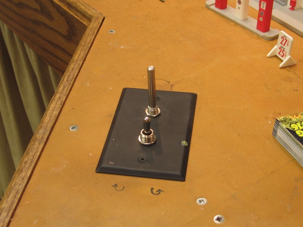
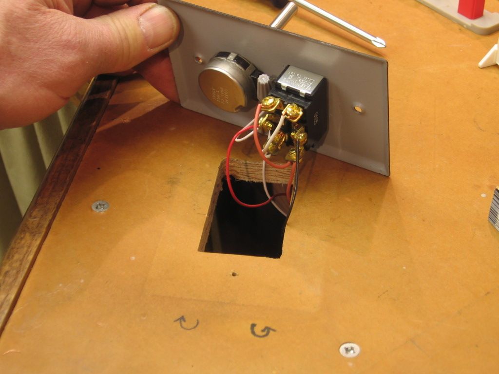
I vary the speed of my turntable with a variable resistor, long shaft, top in picture.. The momentary, off, momentary, double pole, double throw, cross over switch reverses direction. Push and hold. Without doing a lot more research, I believe it's 0 to 250 ohms, could stand to be a bit less, IMO, depends on how much of the full turn of the rheostat you wish to use. The resistance used would depend on the motor(s) current draw in series to determine voltage drop over the resistor, I think?? You could set a pot/variable resistor on each table and tweak them to match.
Variable resistor left in picture/ Double pole cross over switch right in picture.
The tables are linked mechanically by a metal strip which is slid thru the support clamps for the table center rail. the single strip extends from the outside end of one table rail all the way to the outside end of the other table. The tables are well connected, but the faster table can still pull the pair out of sync due to the gap on each side between the wheels and the guide rail. The tables cannot be separated to close the gap due to the necessity for the component which make up the center and side rails for the engine to clear the stub tracks.
As to the suggestion to wire the motors in series. These are new release tables from the nineties. I haven't dug deeply enough to get past the circuit board which i right under the roof and over the motor. Suspect that the board is a rectifier and motors are DC. If they are DC, doesn't that create a whole different problem than dealing with AC motors?
I understand you have come up with a workable solution. So if these additional questions are just beating the proverbial dead horse then feel free to ignore. But in the spirit of a forum discussion, I've never seen a tandem table in action and am curious about how they work.
When the tandem tables reach the destination do you, in practice, have to move one or both back and forth a bit to align each with the stub tracks?
If it is impractical to rigidly lock the two tables together, I don't think a motor speed matching system (series connected motors or whatever) is enough. That is, if I understand your last post about mechanical "slop" you have to independently align the ends of the table to match the respective stubs.
I assume these tables don't have a "snap-into-place" mechanism that insures final alignment on each stub side?
As you've stated, Lionel in their instructions acknowledges the challenge of using tandem tables. One would think if the solution was as simple as re-connecting the motors in series (or whatever) that they would have provided the connectors or instructions to do so.
One would think if the solution was as simple as re-connecting the motors in series (or whatever) that they would have provided the connectors or instructions to do so.
Not so on the original 350, as it had a series-wound open frame universal motor with a double-wound field for reversing, making wiring the motors in series a challenge, hence the recommendation for a variable resistor.
On the 2001 reissue 14113, the mechanism has been simplified with an easily reversed permanent magnet DC motor. A resistor or rheostat would not work as well as they reduce current, not voltage, and can motors draw very little current compared to the old AC motor.
If you isolate one motor from its control, at the motor leads(can be temporary - easily reversed to restore) and tap those two terminals into just one of the leads to the other motor wiring the isolated motor in series, this should for the most part solve the uneven speed issue. The tighter the physical connection, the better it will work.
It works like this - when the faster motor tries to overcome the slower, the current through the faster motor will increase due to the load, causing the voltage to the slower motor to increase and catch up. The transition should be seamless, as with dual-motored diesels with their DC motors wired in series.
Wiring or operating the motors in parallel without some sort of compensation, as delivered from the factory, will result in binding of the mechanisms.
In response to Stan's questions, Yes, there is often a slight alignment adjustment necessary, but this is minimized by releasing the button on the faster table controller for a second or two to allow the slower table to catch up during the move from track to track. The metal strip under the tables helps a lot to keep them in alignment. I am working on a design for a replacement for the 24 track pins at the table ends of the stub tracks to provide the necessary support for pickup rollers and wheel flanges without interfering with table components when the table is moving. The notion of a "snap into place system" is probably not doable because the motor system is probable not powerful enough to break free to move to the next stub track, especially when moving a heavy steam engine and tender.
As the Greenberg Repair manual says of the AC motor version, "the tables must be connected rigidly together" and nevertheless goes on to discuss your adjustable 3-ohm, 10 watt resistor "if the motors do not synchronize closely enough."
For a snap into place mechanism I was thinking of a electro-mechanism that would push a pin into a hole in each stub wall to perform the final alignment and locking. So there would be a lock trigger and unlock trigger whether manual or automatic but only when the motors are stopped. Obviously this is over-thinking the problem but keeps the mind active. Like moving cars back-and-forth to position them over the uncoupling electromagnet, it adds to the "play value"...


