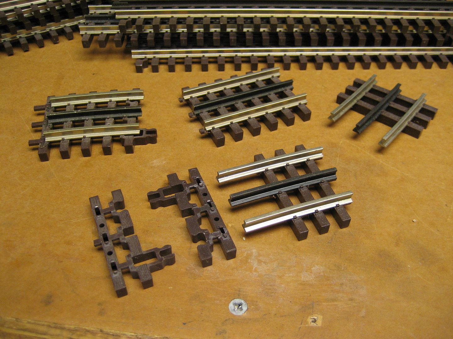
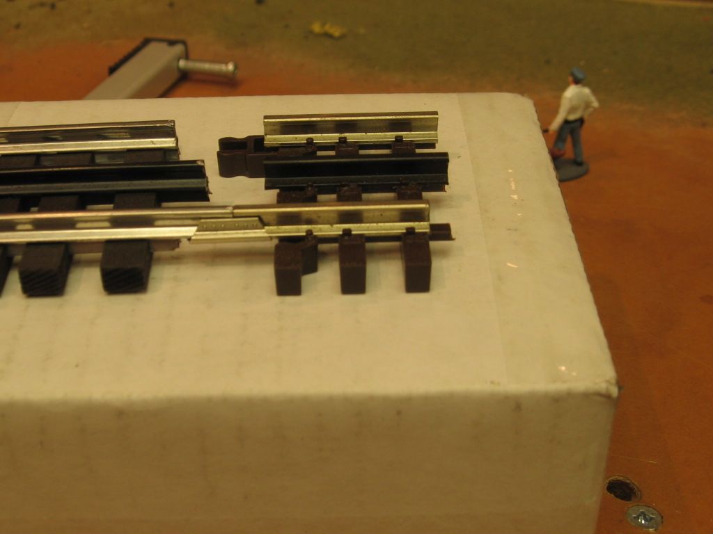
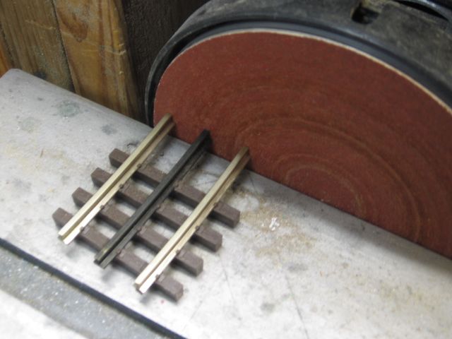
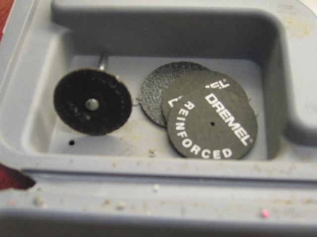
Hi all, I started a new layout with help from members here (DoubleDaz) Dave, Carl on the layout ideas and started using Atlas 3 rail track and wondering about the track connections. Some of the track connections have a small gap in the connection I used new rail joiners since I had to cut track for the layout. Is that going to be a problem for connectivity between the tracks or will the rail joiners make it ok for a small gap between tracks. Would I need to solder each connection for good connectivity? ( a big job) I purchased a 6" cut off saw from Harbor Freight so the cuts are clean but some have small gaps. I notice the rails are a bit flimsy and snap off easily when pushing track together.
Another question I have is about my DCS and using feeders wires ( yes I have the download book, but looking for other idea methods) are they really necessary for my horse shoe type layout that is 16 x 16 x 10 with some areas 2 foot wide down one 16 foot area. Would there be a signal problems with this size ? and if feeders are required, what is the best and easy way to run them. I do have an MTH Z-4000, an old 275 zw lionel, old 125 w, and (2) 80w Lionel transformers, so power is their. Thanks for the help