Fred, I have not seen any posts denigrating your work.  Your track is way better looking than mine, studs and all.  Your photos are superb.

The opinions being offered are part of a legitimate discussion.  I thought that you had determined two years ago that 2-rail was cheaper and easier than stud rail.

Insulated wheelsets for O Scale were available in 1949. I am looking at a 1937 catalog that offers insulated steam drivers.  They offered wide or narrow tread.  My first O Scale car was 2-rail, purchased in 1955.

Opinions are free.  What would three feet of stud rail cost? An insulated freight car wheel, set, brand new, is approaching four bucks.  Drivers are difficult, since there are plenty of used drivers on the market.  Some of us machine our own.

Yes, insulated wheel sets were available in 1949 but not necessarily common. Converting everything over gets expensive. Selling everything and repurchasing everything in 2 rail is eau to say but functionally a big money loser and most likely lacks the replacement availability. That's a nice suggestion but not realistic for most. 

I have a new technique idea for stud rail that may make it quite cheap and easy to do. I need to try it. The nice thing about converting engines to sliders is that you slowly do the engines and the track comes later. A slider works on a solid center rail. The track comes last. 

I welcome opinions. I don't welcome incessant suggestions that it's a waste of time or that there are too many compromises. No there aren't. There are no more compromises than 2 rail or any other scale as compromise is in the eye of the beholder and those comparisons often devolve into the ridiculous. Fortunately we didn't get into the inaccuracy of plastic ties, nickel silver rails, or electrified main rails. It's ALL a compromise. 

I did go 2 rail because it was easier for me. I own a grand total of 5 engines and 4 of them are 3/2 capable. All of my rolling stock has scale wheels, which are insulated. I already had DCC so committed to it. I actually hate track wiring which is an irony with my interest in stud rail so I've decided to go battery power. These are personal choices. I wanted stud rail originally because I wanted to run my dad's old trains or my son's Lionel stuff on the same layout. That was the compromise that I was willing to make for an acceptably realistic looking track system. Stud rail met those goals. I've since decided to not worry about compatibility. 

If you already have 3-rail equipment that you enjoy and you don't want to convert to 2-rail (for all sorts of good reasons), but still like the idea of track that appears more realistic, then the stud system seems like good compromise. It almost seems as if arguing about 3-rail versus 2-rail has become a hobby in itself. Everything about this hobby involves compromises. Even real railroads have to make compromises between what's ideal and what's affordable and possible.

BOB2, I certainly welcome your opinion and hold no ill feelings towards you, so hopefully you haven't felt that way. It seems like you've spent most of your effort in this thread telling people to just go full 2 rail.  You've told people to sell off their stuff, convert it, or suck it up and accept the market for what it is. That's not the point of the thread. The point is in showing how to achieve a better looking 3 rail system than what is out there. For some, it is using a smaller center rail. For others, like me, it's about eliminating the solid line down the middle while retaining the electrical functionality. It's not about what is easy or cheap.

As I've stated, I'm actually a 2 railer. I'm also fascinated by other techniques, which is why I tinker with them. At heart I'm a track person. I love track. I'll gladly accept some compromise in detail on trains before I will on track. That's certainly ironic considering my fascination for outside 3rd rail and stud rail. My switch to 2 rail actually came about from the backlash from the 3 rail people, rather than convincing from 2 railers. I still like experimenting. I look at things not so much from directly copying a prototype standpoint but rather from what can be done with a model to approach a prototype look that based on the existing limitations. This limitations could be based on curve radius or how the track power is setup, as in 2 rail or 3 rail. It's understood that compromises will be made based on situation. 

Last edited by fredswain

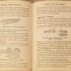
This is from a British book called "Electric Model Railways", first published in 1946. The author wrote his dedicated 2 rail book in 1947 as his stud rail book in 1949. An interesting note in this book however is his opinion that ultimately outside 3rd rail would win out to inside 3rd rail due to its looks and possessing fewer compromises. He definitely didn't win that one. 20170826_11013920170826_110115

Attachments

Images (2)
  • 20170826_110139
  • 20170826_110115

After reading the old book, it is now apparent to me that I, Hugo, and others that have pursued stud rail using a laser cut or stamped center rail with integral studs have drastically over thought the problem. It's clear that we were all set on one train of thought based on Marklin track and their use of a stud at every tie. All of us merely moved them to between the ties. We also used short clip on sliders. 

The book actually sets out a standard for how things should be done. In O scale, a stud is used every 3" or less apart. The more studs there are, the more likely they are to click from the shoes. Stud heights are standardised as well. The sliding shoe should be 3-3/8" long and centered on the wheelbase that rotates. In other words, centered on steam engine drivers or on a diesel truck. Only 1 is needed per engine.

The sliding shoe is the labor intensive part of the old plans as they aren't merely clip on but rather full modification to the engine. Modern 3D printing may make a sliding shoe attachment mechanism easier to accomplish. I'll play with this later. For the time being, I'll do whatever it takes to modify a postwar Lionel engine and will focus instead on making the actual track conversion work. The long shoe should, if applied properly, still clear on even 0-27 track. 

I've slightly modified their plans as they called for long brass pins to be driven through a base board and then individually soldered to a wire. I have a different idea. A previous experiment that I tried several years ago, that is shown on the previous thread page, used brass pins driven through copper tape. It worked. I've decided to see if I could do the same thing with wire instead. 

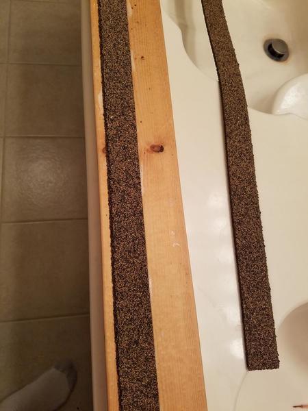
The pictures that follow show that experiment. I've sandwiched a stand of 14 gauge speaker wire, since its what I had on hand, between each piece of cork roadbed. I've glued down a piece of Micro Engineering code 148 flex track, again because it's what I had, on top of it, being careful to center it over the wire. The plan is to hammer brass escutcheon pins between the ties through the wire, completing the connection. The spacing being 2.75" apart and chosen due to the tie spacing of the flex track. That's 4 pins per foot. I bought the pins at Lowes. They are $1.30 per container, which at a guess is around 150 pins. Speaker wire is cheap. If this works, it's pennies per foot and should work with Ross track and switches. I'll experiment with that later if this works. Laying the roadbed and the track piece with the wire takes no more time than laying it for 2 rail. 

The picture that shows the copper strips on top of the track is only there for reference to show where the pins will go. Stay tuned as this experiment progresses. So far it's ridiculously cheap and easy. 20170826_18095720170826_18351520170826_18352020170826_18353820170826_190229
Attachments

Images (5)
  • 20170826_180957
  • 20170826_183515
  • 20170826_183520
  • 20170826_183538
  • 20170826_190229

It's apparent that I'll need a solid surface to hammer the nails into as the wire itself just won't do. That leaves 2 options. One is to go through the ties. The other is to place pieces of wood between the ties that are lower than the ties that I can run the pins through. I used my Chopper to cut some basswood strips the same length as the ties. This took all of a couple of minutes. I then placed a small dimple at the exact center of each piece. Now all I need to do is place these between the ties where I intend to place the studs. Since the ends line up with the ties, I now have the exact center for the pin between each tie. The strip will align the pin and also sit low enough that ballast will cover it completely. Easy so far. Next is to see if the idea works as easy as it sounds. 20170826_201811

Attachments

Images (1)
  • 20170826_201811

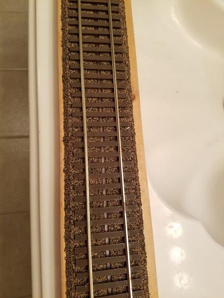
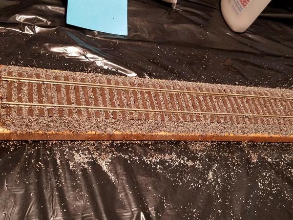
Here are the pin alignment plates in place. As you can see they automatically line up in the center between the rails. They clearly sit low enough to be ballasted over. You can also see that they are centered over the wire. The pins "should" penetrate the wire and complete the circuit. So far, it has been ridiculously easy. 20170826_203321
Attachments

Images (1)
  • 20170826_203321

With a dremel and the right bit, it's a cinch to drill through the ME ties and add the pin. I highly recommend you super glue the brads. You are going to have to drill into the tv cable as well to get the pins to stick through the plastic sheath. Might as well do it all with each tie you do. You probably don't want to be pounding the pins in and busting up the track gauge.

Just my thoughts as I have a lot of experience doing this sort of thing.

All the best,

Ron H

Driving the nail through a smaller-diameter hole drilled in the tie (if you don't find it objectionable to locate the nail in the tie itself ) might give the nail better support, particularly because the nail would then project above the top of the tie somewhat less than it would above the top of a narrow piece of wood placed between the ties. In other words, if driven through a tie, the nail would be stabilized closer to the point where the slider contacts it.  It might turn out to be unnecessary, but with Micro Engineering track, in which the ties are actually hollow, you could glued a piece of wood into the bottom of every 8th tie (that looks the spacing you are using, to judge from the photo) and then drill through that as well in order to hold the pin solidly in place. My concern is that if the nail or pin is not sufficiently rigid, the slider may push it out of alignment.

What you are working on is very interesting and ingenious. 

 The old standard says that the pin should be 1/16" above tie level. PCB board is 1/16" thick and I have some pcb ties. I'm using them as height gauges and am just hammering the studs in until the bottom of the head touches. It's ever so slightly higher than the old standard as it was measured from the top but very easy to do. So far it works perfectly. 20170826_21004720170826_210053

Attachments

Images (2)
  • 20170826_210047
  • 20170826_210053

One could certainly go through the ties. I chose this because I found it easier. All I had to do was dimple the pin location using a pen. The pin was then hammered through and easily went through the wire insulation. No drilling anywhere. The pcb tie jig makes the height perfect, which would be the same height if they were in the ties themselves. They are quite secure. No drilling necessary. I tried pulling one out with pliers but I'm afraid I'll pull the entire track up in the process. They are really in there! Once ballasted, they'll be even more secure. You could potentially hammer them through gargraves or Ross ties. I experimented on an old piece of gargraves and had a few ties split. I didn't see that problem with Ross. I very slightly saw it on a couple of these pieces but they'll never be seen anyways. So far so good. I'm not going to paint or detail it. I'm just going to ballast it. 

Really nice work Fred.  Stud rail seems like the best compromise for O scale.  If you add proper scale couplers, then you achieve the scale appearance of 2-Rail, while maintaining the sharper curves permitted by 3-Rail equipment, at least O-72 for larger locomotives and scale passenger cars, that most of us need for space considerations.  In other words, the scale looks of 2-Rail with the space advantages of 3-Rail.  I really hope that this catches on in a big way.

Fred, watching the hurricane news from Houston, I hope that all is OK for you down there.

J

I did find out that the postwar engine I was going to covert has large wheel flanges that hit the ties on this code 148 rail. Gargraves 2 rail would work fine. I'll test it at a later date. It won't look perfectly scale but would be much nicer. The sliding shoes will be the challenge. Fortunately, they'll work on conventional 3 rail track too.

The water got within 6" of our house last night but the break in the rain has allowed it to drain off so the street is passable again. We are in Clear Lake near NASA so we are near the bay where it drains. The situation throughout the city is mind boggling. 

Last edited by fredswain
fredswain posted:

I did find out that the postwar engine I was going to covert has large wheel flanges that hit the ties on this code 148 rail. Gargraves 2 rail would work fine. I'll test it at a later date. It won't look perfectly scale but would be much nicer. The sliding shoes will be the challenge. Fortunately, they'll work on conventional 3 rail track to.

The water got within 6" of our house last night but the break in the rain has allowed it to drain off so the street is passable again. We are in Clear Lake near NASA so we are near the bay where it drains. The situation throughout the city is mind boggling. 

Good to hear that the water did not cause any damage to your house (and the trains inside!).

What Code is Gargraves 2-Rail?  And what Code is the lowest profile that will work with 3-Rail wheels?  I know that 3-Rail wheel flanges vary, but would Code 172 be the lowest "safe" profile for all 3-Rail wheels?


Last edited by Jtrain

Gargraves and Ross both measure out to around code 215. That's what Atlas 3 rail track is. It's a rail code that micro engineering sells in bulk as well. Many deep flange wheels just barely clear on code 148 but it's literally hit or miss. Code 172 would probably take care of most wheels but it isn't made anymore. I have a few hundred feet of it. Code 205 is the next size that micro engineering sells and would be the logical choice from what's available. It's only ever so slightly taller than MTH Scaletrax. 

On a slightly different topic, it is not the number of rails that determines the radius of curves or the kind of equipment that can be operated through them. As far as I know, the main reason most 2-rail steam engines (e.g Sunset/3rd Rail) require a larger-radius curve than the same 3-rail steamers is that 2-rail engines generally do not have blind drivers. Given the same arrangement of blind drivers, a 2-rail engine would be able go around the same curves as its 3-rail counterpart. The 2-rail and 3-rail Sunset models appear to be mechanically the same machines in all respects other than flange depth and presence or absence of blind drivers.


B Smith posted:

On a slightly different topic, it is not the number of rails that determines the radius of curves or the kind of equipment that can be operated through them. As far as I know, the main reason most 2-rail steam engines (e.g Sunset/3rd Rail) require a larger-radius curve than the same 3-rail steamers is that 2-rail engines generally do not have blind drivers. Given the same arrangement of blind drivers, a 2-rail engine would be able go around the same curves as its 3-rail counterpart. The 2-rail and 3-rail Sunset models appear to be mechanically the same machines in all respects other than flange depth and presence or absence of blind drivers.


And also other 3-Rail model modifications such as swinging pilots and coupler mounting locations/methods, right?  And the deeper wheel flanges also help prevent derailments on the tighter curves, right?

Yes, but those are all minor modifications. My point is that whether the track has 2 rails or 3 rails is not the determining factor when it comes to minimum radius. With some simple changes at the factory, a 2-rail engine could go around the same tight curve as its 3-rail counterpart, and also pull a train. As for flanges, I'm not sure the deep flanges are really necessary: most 2-rail modelers today are using wheels with a shallower flange and narrower tread than 50 years ago, and the Proto:48 modelers are running trains just fine with scale flanges and scale tread.


B Smith posted:

Yes, but those are all minor modifications. My point is that whether the track has 2 rails or 3 rails is not the determining factor when it comes to minimum radius. With some simple changes at the factory, a 2-rail engine could go around the same tight curve as its 3-rail counterpart, and also pull a train. As for flanges, I'm not sure the deep flanges are really necessary: most 2-rail modelers today are using wheels with a shallower flange and narrower tread than 50 years ago, and the Proto:48 modelers are running trains just fine with scale flanges and scale tread.


I like to point that out to people who think that 2R takes more space than 3R. Sure, out of the box with all drivers flanged, pilots fixed, tailbeam details, etc... they will require broader cures. But the same 3R compromises can be applied if tighter radius curves are desired or required.

With well-laid curves (tinplate flanges seem to be immune to less-than well-laid curves) a 2R Mikado will run on O-72 curves. Barely. My Lobaugh Berk's driving wheelbase does; however, the tail beam has to be narrowed to allow the trailing truck to swing.
Other compromises with locos that have 4-wheel lead trucks (especially those marketed for curves less than O-72) involve reducing wheel size and/or stretching the lead truck wheelbase and/or shrinking the size of the cylinders. Some manufacturers (Williams, e.g.) also stretch the length of the pilot beam and, maybe, the length of the boiler. As far as I know, 3rd Rail designs such locos without these flaws.....well, maybe lead truck wheel diameter.

My (limited) experience with diesel models is that a number of earlier production units have excessively deep flanges for use on code 148 rail. Otherwise, there is plenty of experience on OGR about fixing swinging pilots for use on O-72 curves.It's part of the "modeling" fun of our hobby.


I've run scale wheel, body mounted kadee's on 40' scale cars successfully on 21" radius track that I hand laid on a 4x8 layout. It was really tight but the bodies didn't hit. I'd have needed truck mount couplers to go tighter. It was using old brass outside rail engines with the old .172 wheel profile. One engine was a 2-6-0 and the other an 0-8-0.  The 0-8-0 has blind flanges on the inner drivers. My MTH premier GP38 with scale wheels and fixed pilots also worked. The large SD70's and AC4400's didn't unless they had swinging pilots. I have an older lower end Lionel 2-6-4 steam engine that I filed the deep flanges down on to run on lower rail code. It still turns sharp but doesn't work well on Lionel tubular rail anymore. 

Last edited by fredswain

Fred, you have always been an inspiration to me. This time though you have really done it! This idea seems so straight forward and simple that I have to try it. I'm going to take my 2R Gargraves and create a test switching module. Could you please post photos of your slider design(s)? That's the only part that I am unsure of at this point.

Thanks!

The difficulty of the slider is going to more than offset the simplicity of the track. I haven't built it yet and with the historic flooding here I don't know when I will. Place your studs 2-1/2" to 3" apart. Hold that range. Your slider will be 3/8" longer than your distance. It will not be a clip on. It will need to move up and down but remain level. I'll show this when I get a chance. 

fredswain posted:

The difficulty of the slider is going to more than offset the simplicity of the track. I haven't built it yet and with the historic flooding here I don't know when I will. Place your studs 2-1/2" to 3" apart. Hold that range. Your slider will be 3/8" longer than your distance. It will not be a clip on. It will need to move up and down but remain level. I'll show this when I get a chance. 

Fred:

Brilliant work. The pins are barely visible with the ballast in place.

Have you considered getting replacement pickup rollers, removing the roller itself and using the framework as a mount for the slider? The slider would float and swivel due to the spring and pivot. The catch is you'd need to drill a small hole in the slider for a screwdriver to mount the slider to the locomotive.

Last edited by AGHRMatt

 I'm going to attempt to design something that screws on in place of the rollers. It might be something that can be printed with the slider attached to it. I don't now yet. If that technique works, over time more and more engines could be done. Remember, I'm just doing this as an experiment based on old standards to see how it works so I'm not planning to develop this very widely.

jonnyspeed posted:

Fred, you have always been an inspiration to me. This time though you have really done it! This idea seems so straight forward and simple that I have to try it. I'm going to take my 2R Gargraves and create a test switching module. Could you please post photos of your slider design(s)? That's the only part that I am unsure of at this point.

Thanks!

The studs need to rise to clear the running rails at switches. The highest studs adjacent to the rails in the switch need to be 1/16" above the running rails. The slider does not ride on the running rails. Each successive stud, at your normal spacing, is 1/32" lower until you get to the lowest level. The rise is very gradual over distance. Your stud height will be 1/16" above tie level on the main track sections, as mine is, but will be automatically lower than rail top height than mine due to rail code differences. 

fredswain posted:

The difficulty of the slider is going to more than offset the simplicity of the track. I haven't built it yet and with the historic flooding here I don't know when I will. Place your studs 2-1/2" to 3" apart. Hold that range. Your slider will be 3/8" longer than your distance. It will not be a clip on. It will need to move up and down but remain level. I'll show this when I get a chance. 

So it sounds like you are actually bridging the gap between the rollers then? In my mind I was picturing a "shoe" for each roller. Hmmm... I wonder if something like this would work:

slider

Attachments

Images (1)
  • slider

Add Reply

Post

OGR Publishing, Inc., 1310 Eastside Centre Ct, Suite 6, Mountain Home, AR 72653
800-980-OGRR (6477)
www.ogaugerr.com

×
×
×
×
Link copied to your clipboard.
×
×