
Well… we did it. In four weekends we did two graduations and one Bar Mitzvah, none closer to home than 200 miles (Champaign IL, Ann Arbor MI and State College PA). We drove home from State College on a Monday and Tuesday and traffic was wonderfully light.

I finished the stairs by just using Tamiya Fine Gray Primer, sanding some off the stair treads to show some minor wear, added a few nut/bolt/washer castings and then some minor rust runs. I painted the base a concrete mix of Tamiya Buff and Neutral Gray. I found I had to elevate the base a bit to align better with the doors. I used a scrap piece of foam core to raise it. The reason for this is the power lead is not sitting directly over the previously drilled hole (where the Apppliance Store's lead went) so it was holding the building too high off the surface. I will be removing the Hardware Store when I finish the interior so I will redrill the hole at that time.

To prepare the site I had to remove the Bar Mills PE sidewalk elevator. This was CA'd in place so it left some residue that I had to remove. I had painted the pavement under the elevator flat black. I thought I was going to have to repaint the smooth, but this was unnecessary as the Hardware Store came out further and covered all the old stuff.concrete after sanding it.

And here's the rear with the stairs just sitting there. I will glue them down after the final work is done.

And here are a series of frontal shots.


And at "night"...

In the above you can see a temporary spot for the appliance store; in the curve just north of the Sunday Morning mockup. It's a tight squeeze and should probably go where the Gravely Building now sits.

I'm going to keep bugging the store owner to get me those interior pictures. Meanwhile, I'll be doing some plastic kits. My 3D printer is down. I'm getting a new mother board from Elegoo and that's going to take a while to get here. They're a pretty good bunch. Even though the printer is 5 months out of warranty, they are giving me the new board. It just abruptly stopped working and we're hoping this will solve the problem.

Attachments

Images (9)
  • mceclip0
  • mceclip1
  • mceclip2
  • mceclip4
  • mceclip5
  • mceclip6
  • mceclip8
  • mceclip9
  • mceclip10
Last edited by Trainman2001

Thanks guys! I'm fix'n to let out the contract for cutting Sunday Morning. SketchUp Pro just got a whole lot more expensive. They've just notified users that the price is going up over 40% next year for the year subscription. I just paid this year's renewal at $237.00 and next year it's going to be $346.00. I don't know how they can justify that increase. It's getting really expensive for the occasional user like me.

They have the "Free" version available, but it's no longer a client version residing on your own computer. It's in the cloud. Furthermore, it does not permit using any of the add-ins and extensions that I use. And I have a ton of them including the Podium rendering software, which in itself is an expensive (for me) yearly charge. Together they'll be close to $500/year, and that's way over the top for the hobbyist like myself. To help pay for the software I've cancelled almost all of my print magazines except for Scientific American and Fine Scale Modeling. They didn't add up anything near $500.00. That places software as a much higher expense than the hardware I use. Good 3D printers are $300 or less today.

I don't use SketchUp every day. I use it when I'm designing a project and then not much at all. It averages about 1 to 2 times a month. That's more than $40 every time I touch. That's expensive!!

There are other 3D packages out there. Blender and Mesh Mixer stand out as powerful packages. But they're very difficult to master and I've been on SketchUp since Ver. 1.0 in the 1990s. You can teach and old dog new tricks, but it takes a whole lot longer. I may have to bite the bullet and master them and then dump SU. They're getting piggy.

I'm afraid I have to agree that mastering one of the open-source alternatives is the only sensible path forward for the non-professional.

I use something called SolidPython, which lets me do solid models by writing code rather than directly manipulating graphical 3-D images. It is very powerful, easily supports full parametric design, and is vastly simpler than the mainstream CAD systems. The problem is that it is really only suitable for someone who is very comfortable thinking in code, which makes for a relatively small population for whom this makes sense. For everybody else, picking a package and biting the bullet is probably the only reasonable alternative. FreeCad is probably the most powerful of the free systems, but learning it is kind of a nightmare. I was once fairly good at it, but I've forgotten it all.

Myles, another award-winning building completed.

I have been using Autodesk Light for sketching (design) but it doesn't output anything that can be input into my "FREE" copy of Autodesk Fusion 360 except a DXF sketch that can be copied into Fusion as a guide.

Autodesk offers a "free" subscription of Fusion 360 to students and enthusiasts with yearly renewal.

However, after using Pro Engineer before I retired from Honeywell. it isn't as user friendly as the way you have described SU in previous posts.

For occasional users it's hard to justify the premiums for subscription's they are asking.

Gerry

Last edited by SGMret

I have the free version of Fusion 360, Blender and Mesh Mixer. I was in the process of learning all of them, and not liking it. I then decided to bite the bullet and get my SU pro renewal. Now I'm back to that previous state. SU from its inception was much more intuitive. Things went south when Trimble bought it from Google.

The history is as follows: SU was founded by some fellows in Boulder, CO. Google used it to do 3D drawing for their Google Earth app. They liked it so much they bought the company. Google contiued to offer it as a free package. I was using SU from its beginning before Google. Then Google sold it to Trimble. Trimble clearly wanted to monetize it. They converted the free version, which was full-function product that resided on your own machine, to a cloud version that was very limited in capability. The only restriction on the previous free version was "No Commercial Use" whatsoerver; even if it was secondary.

They then offered the Pro version as a fixed price. Then it became a yearly subscription. And then they raised the price more. Most of the development of this program was done a long time ago. Trimble has made some tweaks, but nothing major. A lot of development was in the outside developer world with hundreds of add-ins and extension to increase the program's power. None of those extensions are available to the free user. You have to buy Pro. Without them, the program is relegated to doing rudimentary things, and is not sufficient for my needs.

The other programs, like Blender, have their strengths. Blender and Mesh Mixer are good at drawing organic shapes with compound curves and contours. However, to use Blender as an example, the variables you have to control with a constant barrage of dialog boxes and choices is mind boggling to me. I can learn! I'm old, but I'm learning constantly. I mastered 3D printer at 75. I learned to make my own decals recently. I learned to draw buildings for laser cutting six years ago. I didn't start scratch-building until age 65. But, I don't like having to learn new things that don't advance my art. I'm having to learn all this because the product that I've been successfully using for 25 years has priced itself out of my reach.

I've just penned a post describing this dilemma on SU's User Forum.

Last edited by Trainman2001

Myles,

I understand completely. It's been 5 years now since the learning experience began with a new 3D software program after using the more intuitive Pro Engineer 3D modeling program as I said above. At the age of 83 I to don't enjoy starting from scratch either.

My back door approach started when I wanted to scratch build PRR style positional signals using styrene. Since I needed 20 or more and had no turning ability that Allan Rail stepped in and agreed to 3D print the finials for me. As you would expect I soon found it would be time consuming and tedious that I started looking for 3D software and printers. You'reposting about 3d Resin printers,together with Alan's posting sparked my interest in obtaining my own printer and required software. Having used AutoCAD drawing software, I was able to obtain a free copy of their Fusion 360 modeling software and began the learning process once again. Based on your past posting about using SU I agree that Fusion isn't very intuitive and sometime can be frustrating and not as powerful. Although forme, obtaining a individual seat license for Pro Eng would have greatly reduced the learning process, the yearly cost of $1000+ wouldbe out of the question thatI took the free option.

I know you will find a solution to your dilemma just as you have done in the past and continue to provide us with many enjoyable projects to follow.

Gerry

AutoCad started out for almost FREE, just to buy market share. Now its close to $2,000 a year per machine.

AND if they find you have been using the software on more PCs than you purchased THEY back charge you.

if you don't pay they shut down your access.... Neat!


It's costly to have coders, software security engineers, sales, owners at the trough.   

Last edited by AlanRail

My decision was sort of taken away from me when I was informed that my automatic renewal was processed through PayPal. I thought about cancelling it, but after discussions with my understanding wife, we decided that it's important enough for what I do. Furthermore, my lower price from last year was the recipient of a $50 new-signing discount. So the price rise was not really as large as I thought (more like 16%) and I will live with it. I really, really didn't want to master new software considering the vast experience I've had with SU.

Thanks Al!

So just how old are you? I didn't start scratch-building in earnest until I was 65. I didn't start doing serious architectural drawing on SketchUp until I was 70, and didn't start 3D printing until I was 75. Age is just a number. We know now that we can keep building brain connections even when old. That said, cognitive learning is different from motor learning. Motor learning is much harder when old and that ability starts to degrade in our early 20s. BTW: I turn 78 at the end of July.

I don't want to hear any excuses. You're too fine a craftsman to set artificial limitations. As Yoda says, "There is no try! There is do or do not!" Remember, I'm here to help you...

Great building Myles. No matter what they charge for 3D it is still faster and easier than my John Henry style of hand building everything. I am too set in my ways to change but you never know.

I think The second part of your sentence tells it all Alan.  “but you never know”.  I think that can be true for any of us.  Loss of fine motor skills could be a driving force for an ‘older’ person to take on 3D printing.

In all honesty, it isn't easy learning 3D software at any point, and age can be a factor. But you don't know what previous knowledge you have (vast knowledge) that can be applied to shortcut the learning process. We're not little kids who are empty vessels where you just pour stuff into. Granted, as older folks you often have to unlearn stuff in order to fit in new stuff. And that can be challenging.

ALAN-


You are clearly an EXPERT on Plastruct.  You know exactly what dimensions your structures need to take to utilize their designs. Like how the stairs , ladders , railings and patterns must be incorporated in your models.

HOWEVER, with 3D printing there are NO LIMITS, no fixed slopes to the stairs, no fixed widths to the railings.  You make up your own 3D patterns. Toss out your X-acto knives!

Very interesting thread!  I have a lot of respect for the two Alans and Myles is a true inspiration to me.  Myles your buildings are gorgeous!  I love realistic scenery and attention to detail that each of you has in spades.  Thanks for sharing your excellent work and thoughts.

Art

You're welcome. Obviously, it does take some time to write thousands of words to create an 11-year thread, but with comments like your's, it's clearly worth it. I've said it many times, but I'll say it again. I get as much value from my readers as I assume I'm giving. More improtant than the tips and tricks we share, it's the friendships I've developed with folks I've never met in person, but find their comraderie valuable regardless. I'll keep this going as long as there's new stuff worth writing about. That said, Mark Boyce and I actually did meet when he bought my Idaho Hotel.

Last edited by Trainman2001

Myles, you said it so well! 

I get as much value from my readers as I assume I'm giving. More important than the tips and tricks we share, it's the friendships I've developed with folks I've never met in person, but find their comradery valuable regardless. I'll keep this going as long as there's new stuff worth writing about. That said, Mark Boyce and I actually did meet when he bought my Idaho Hotel.

I certainly looked forward to meeting you in person when we arranged the meet for the Idaho Hotel.  Even though it was a short time we were together in the Sheetz parking lot, I was greatly pleased with talking with you and your wife.  Meeting Forum friends in person was the big takeaway the two times I went to York before the pandemic.  I value that far more than the few items I purchased.

Hey guys! it's been a while. I've been working on another Battleship New Jersey project. This time I'm creating a cutawat of the five inch secondary battery turret down to the magazines as I did with the big guns. The ship has already accepted the offer.

These are my drawings: They are not compete nor completely accurate as this time.

mceclip1

I've already started printing parts for it. Not sure how I'm going to handle the magazines. It's not a simple question with these guns. There were 10 turrets on WW2 version Iowa Class ships, but only six magazines to serve them. Four of the magazines served two turrets. To make matters worse, they are not directly below the guns they serve. And if that's not enough, There are intervening decks between the gun and the magazines that do not have any gun-related functions other than the powder and projectile hoist trunks passing through these spaces. There's another possibility as shown by this artists drawing. There is a small intervening space and the gun is sort of over top of the magazine. This would be easier to model, but it is not accurate. My model will be more detailed than this drawing.

This is NOT my drawing:

Here's a sample of the printing.

\

This is not the only project I'm working on at the moment… it's one of five.

Another project is a commission I just received to build a nice holiday-centered n-gauge model railroad for the store window of the Newtown Hardware House. The offer is based on how impressed the owner was seeing the results of the hardware store project. We made the formal agreement yesterday. I'm using the little set that I built with the grandkids 12 years ago, and will modify it and tune it up for the store. I'm also creating some replicas of 19th Century buildings extant in Newtown, PA, including the hardware house in n-gauge and another building several stores away. In this tiny scale I can print the entire building instead of printing dozens of detail pieces and having the walls laser cut. To that end, it wasn't difficult to convert the drawings to make them printable as single pieces. I finished the front wall this evening and it will work.

mceclip7

I'm not worried about those micrscopic window mullions. It was silly to even have them on the print drawings. I will either leave them off, draw lines on the glazing or print decals to apply to the glazing with the mullions in place. There was some slight distortionin the area over the right door, but I'm gong to live with it. Frankly, I'm amazed that it printed this well right out of the gate. The entire roof structure is being printed now. I'm printing the other three walls and the exterior stairs as two parts. That will be a miracle if it prints in n-scale. I'm getting a nice fee for the job and will be replacing some engines and rolling stock, plus spiffing up the layout with some more foliage and special lighting.

As a reminder, here's my proud grandsons 12 years ago when the layout was complete. Alex was probably 8 and Jack 6. Alex is now an engineering grad and Jack is a sophomore at Wash U in St. Louis. My only concern with this layout is the very sharp radii curves. They were the result of the small size of the board we had to work with. I'm hoping we can get it running well enough to run unintended hours on end. The boys actually did a lot of work in building this.

I know this an O'gauge forum, but you'll have to grant me special dispensation for this special project.

Oh… and one more thing… the owner of the store has offered to pick it up at my house in Louisville. He often travels in the South, and his son used to live here so he's quite familiar with the place. This eliminated a huge worry of how to get it to Bucks County, PA by Thanksgiving without breaking it.

I'll keep all y'all abreast of all my projects.

BTW: I'm now 78, and the creative juices haven't slacked off one bit. In fact, I feel as good as I ever have. Even my sciatica finally gave up and went away. Life is Good!

Attachments

Images (9)
  • mceclip1
  • mceclip0
  • mceclip2
  • mceclip3
  • mceclip5
  • mceclip4
  • mceclip6
  • mceclip7
  • mceclip8
Last edited by Trainman2001

Myles, thank you for posting!  The battleship turret looks like another challenging project you will do a dandy job on!

The N scale Newtown Hardware building and layout is a great idea of the owner’s.  It looks like the boys did a nice job with grandpa’s help years back!

Happy belated birthday! I’m glad you are feeling good and that the sciatica pain went away.

I’ll look forward to updates when you have them.

I hope I don't disappoint.

I got the roof and the right side wall printed today. The rear wall is on the printer now and I'll print the left side wall tomorrow. All that will be left will be some floors. I got the down payment on the project so I'll be purchasing some goodies for it. It needs trees and shrubs, plus the lighting. I'm also going to get some new cars and engine. I saw a nice Pennsy 0-6-0 switcher which fits the time period the owner wants to hit… the 1940s.

The roof, while printed in a workable way, had some serious delamination in the center causing depressions in the roof surface. Clearly, it needed more support in that area. It's also possible that the drawing itself had some layering that produced wth discontiunity. Remarkably, the chimneys all formed perfectly.

I strenthened the inner surface with some Bondic while pushing down the bulge from the outside while curing the Bondic on the inside which really flattened it out.

I also copiously filled the big depression on the outside and then sanded the heck out of it.

NHH 160 Roof Bondic Patch

There was one other strange error. There were openings on the rear, gable end of the roof. I really didn't want to print this large part over. Besides the 6 hour print time, I didn't want to waste resin. So I patched it with some thin styrene sheet, filled any gaps with Bondic and we're good to go.

And fixed:

So the roof is ready for paint. No shingles in n-gauge.

The right wall came out very well. With a very little clean up it will be ready to use.

I'm also making good progress on the next building. This building, 5 doors down from the Hardware house, was the offices of the Newtown Newspaper and was built in 1876. It has lovely brickwork especially in the arches around the windows, but alas, those bricks are too small to worry about in n-gauge. It only took a couple of hours to get this far. Have to do windows, roof, and doors. Just noticed that two of the windows upstairs are bricked out. I could add that.

Onward and upward.

Attachments

Images (8)
  • mceclip1
  • NHH 160 Roof Bondic Patch
  • mceclip2
  • mceclip3
  • mceclip4
  • mceclip5
  • mceclip6
  • mceclip7

Some more walls completed. Also got the 5" gun body printed today. When I finished the 16" gun project and the Hardware store, I was wondering how I would keep my printer busy. Boy… was that an uneeded worry. It's been working non-stop for two weeks. Got the rear wall done today and the Left wall just finished a while ago and I'll pull it off the machine tomorrow. I will only have the steps to do, and then assemble. I'm thinking of producing a custom decal with the window mullions that will go behind the transparent styrene windows. I was pleased the the paneling on the doors and shutters came out.

NHH 160 Rear Wall

And the gun… The barrel fit the slide nicely and the gun fit between the mounts perfectly. The curator thinks they look pretty good.

The drawing:

5IP Gun Final

And the print.

5IP Gun Print R

The "mount test". I'm going to machine metal trunnion pins to replace the drawn ones that I made.

5IP Gun Print Mount Test 1

Attachments

Images (4)
  • NHH 160 Rear Wall
  • 5IP Gun Final
  • 5IP Gun Print R
  • 5IP Gun Print Mount Test 1
Last edited by Trainman2001

Myles, having worked in N-scale for about 10 years, I think your printed parts and fills for gaps will work great!  Yes, individual shingles and bricks are mighty tiny in N-scale!!  Then when viewing from an average of 2 to feet away, you don’t really notice them!  That 1876 newspaper building is excellent to model also!   The gun looks great as well!

Yes, I can see the printer is running almost non-stop.  You’ll have to pull maintenance on it pretty soon.  Just kidding there.  😄  The thought did remind me of substation breakers.  If we get in “the way back machine” to your marvelous substation model, each breaker type had a manufacturer recommended time to “pull maintenance” as they called it based on the number of operations since last maintenance.  I’m going back to 1990 give or take.  A lot of old breakers were oil circuit breakers OCBs.  They could handle quite a few operations before the substation electricians hat to switch them out, drain oil, and inspect and replace parts.  The newer breakers were filled with sulfur hexafluoride SF6.  They could take a lot of operations.  We had a couple 500KV air blast breakers at one station.  They used a blast of air to extinguish the arc, and could only take about 10 operations before they needed to pull maintenance.  When they opened the sound waves rocked the control house at least 50 feet away.

Sorry for the long winded monologue.  I’m sure the printer will run well for many, many hours of printing!  😊

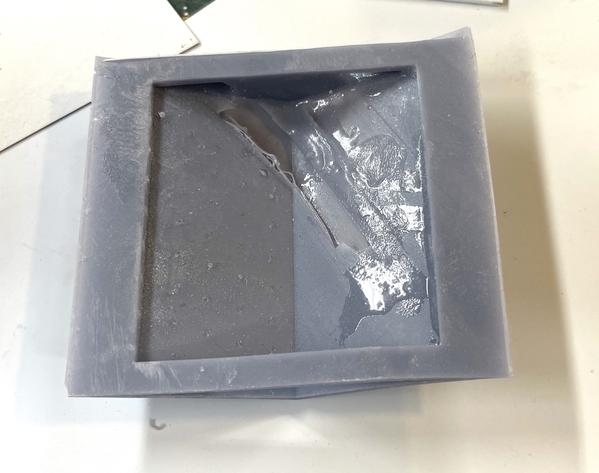
I have had the most printing difficulty that I've had in years printing the last wall of the Hardware House. This is the left side wall which is basically flat with two windows. It's the simplist print of the structure. The first two attempts had failed supports. The third was a complete failure. All that was on the build plate was the base. The rest was a layer of resin spread out all over the FEP.  I was able to remove all this gunk, but I'm a little dubious about the health of the FEP. I just changed it last week and it's only run two print sessions.

Big Print Failure

The lumps cause a bigger problem. The Z-axis comes down to specific heights under some force driven by a stepper motor and lead screw. The force can damage the machine. I have a tempered glass "protective" cover over the LCD screen. When I examined this cover I saw a fine pattern of cracks permeating the entire LCD. I thought it was the glass plate sacrificing itself for sake of the LCD. However, I was able to remove the glass plate perfectly intact and it was the LCD SCREEN THAT WAS CRACKED!

I immediately did a light test with the facility installed in the printer and this was what I saw. Half an image, and you can see the cracking. The LCD is toast. I ordered a new one from Amazon for $47.00. It's not too difficult to install, although there is a bit of fussing with some adhesive strips that hold a lower glass protector and the LCD into the upper frame. There's one ribbon cable that connects to the motherboard, so you must remove the 6 screws on the back panel. So in the last couple of months I've installed a new motherboard, touchpanel and now the LCD screen. All that's left is the fan and the stepper motor.

LCD Failure

Screen is coming on Friday and I'll have it running next week. This is the first time I've ever broken the LCD screen. I had one fail on my older Mars, but it was a few spots that went dead, not a complete break up like this.

Elegoo has come out with a DLP machine. When the resin machines first came on the market about 8 years ago (guesstimate) it was a $30,000 affair that used a DLP projector and some kind of oxygen exchange system that hardened the resin.

For those that heard of DLP, but aren't sure what it is, first of all, it's Texas Instruments product that's found itself in many of the (now obsolete) projection TVs, and video projection systems. It's a microchip that has thousands of tiny prisms on it  that reflect light when individually controlled. When they're facing one way, they reflect the projection light source and when facing the other they project no light. Therefore it does the same job as the LCD, by selectively passing or blocking the pixels to create the layers in the 3D printer. It's more expensive, but because it's physically separated from the z-axis which can do damage when pushing on the LCD, it has a much greater life span. After this experience, my next printer may be the DLP version.

In the color TV applications there is an additional complication. There's a spinning wheel that has color filters in it, Red, Green and Blue. The wheel spin is synchronized with the DLP chip, so when the chip is showing pixels that should be blue, the blue segment is in the optical path, and so on. It's why that this system has been replaced in television use… too much to break.

Sony had another method… a digital light engine that had no moving parts. Instead, the light from a very bright xenon bulb enters the light box and hits a dichroic mirror. This mirror refracted the xenon beam reflecting the blue information to the left, and passing the yellow through. The yellow goes through another mirror filter where the green light is separated and passed to the left transmitting the red component. The red is reflected off some standard mirrors around two more corners. This creates three beams that enter a very unique component. It's a square with three LCDs on three of the four faces. The left one controls the blue components of the picture, the center one controls the green, and the one around the other side controls the red. These three colored xenon illuminated streams containing picture information are blended in a very unique prism. The result is a full-color picture projected onto the screen surface (from the back) through another clever mirror lens system.

The Sony system was excellent, but had one fatal flaw. The xenon bulb was so hot that it eventually destroyed the blue LCD. The blue was the first one in the optical chain and therefore absorbed most of the heat. This problem was eventually solved in all these systems by using LEDs as the light source and dumping the xenon systems. While high powered LEDs do have some heating, it's way less than any plasma/incandescent source.

And that's my lesson for today.

Attachments

Images (2)
  • Big Print Failure
  • LCD Failure

I am happy to report that the printer is back running. In the last few months I have replaced motherboard, touch panel and LCD board. All that's left is the UV unit and the Z-axis stepper motor. I'm not looking forward to replacing either of them.

That said, it wasn't without it's usual complications.

I viewed the video to make the replacement and noted that below the LCD panel was a rather thick piece of plate glass that served as a protector of the LCD probably to reduce the heat loading. When the guy in the video removed the LCD it came up with the glass plate which he then separated. The LCD is held to the glass plate and the plate to the upper casting of the printer by narrow, double-sided adhesive strips. By seeing this I made two incorrect assumptions; the it was essential to remove the glass plate AND a new plate was included with the new LCD. I jumped the gun by doing the disassembly before the product was delivered.

When I pryed up the LCD, only it came up. This was after removing the back plate and disconnected the ribbon cable from the motherboard. When I attempted to pry up the glass plate, I broke off a corner in trying to lift it. I got it off, but it was no longer pristine.

I had two chips, but not realizing that I was going to have to reuse this broken plate, I threw the smaller one away.

Then the new LCD arrived without a glass plate. I glued the big chip back in place with thin CA. BTW: Did you know that Kodak invented CA as Eastman 501 to glue lenses together. It works great on glass. And then I attempted to reform the missing corner using Bondic. I applied it in layers and then carefully shaped and polished it so it had the correct geometry. Then when  doing a final cleaning my repair fell off. Unlike CA, Bondic doesn't make a strong bond with glass. I then realized that the missing part was not in the light path and I used it as is.

I've contacted Elegoo to get a new plate and they have responded. They're good to work with.

You connect the new ribbon cable to the LCD first and then slide it down a slot behind the LCD into the motherboard compartment. Or that's how it's supposed to go.

It seems that the ribbon can either go into the motherboard compartment or the light box. You don't know which (kind of little Schodinger's Cat…) until you turn the unit around to attach the cable to the motherboard. As I've said many times, when given a 50/50 chance to get something wrong, I usually get it wrong. When I turned the unit around, there was no ribbon cable near the mother board.

This could have worked out very badly since I had to removed the sealant tape around the newly installed LCD, then pry it loose from the newly applied double-sided tape, pulling the cable out of the slot and re-inserting it so it goes backwards towards the motherboard. Too bad there's no dialog on the instructional video. It would have been nice to know this.

I now printed the last wall of the Hardware House in n-gauge. I've also printed the front wall of the next little building, another Newtown Gem. The wall had a little warp. While still soft I clamped some brass channel to the part to flatten it and then put in the UV post-cure chamber.

NHH160 Curing the walls

I got the little layout running. There were some hitches which I'm working on. I tried it with the one diesel that still worked and got it tracking well enough. Today I went to the hobby shop to get some more stuff and bought a little Pennsy 0-6-0 switcher. It didn't work so well. The fellows at the shop said they don't have the tractive effort of the diesel and I have steep slopes and it slipped like crazy with just four cars trailing. I'm taking it back along with some more frieght cars I bought.

Now I have to figure out how to do realistic snow in n-guage.

Here's the other building which I finished drawing yesterday.

I'll keep you all posted.

Attachments

Images (2)
  • NHH160 Curing the walls
  • mceclip0
Videos (1)
Steam Loco Test

Short note. First: I hate n-gauge! They just don't work for me. Everytime I fix one derailment, I bump another car and derail it.

I'm getting better and bought a RIX hand rerailer and that helped a lot. I got one engine to run a train of five cars for almost a half hour without a derailment, but that's not good enough. It has to run indefinitely without one. Then I found the bad spot. The engine would jump prior to entering a switch and derail. It wasn't a nice transition from one track piece to another, so I kept filling gaps and filing lumps, but didn't quite get it. I thought maybe the gauge was wide at that spot due to all my fussing. I measured a normal track flange distance with a digital caliper and got somewhere around  0.0347-0.350". This spot wasn't loose. It was tight! I got out the Dremel with a diamond burr and removed more stock further smoothing the trasistion. Problem solved.

It thought the problem was the joint just before the switch and did work there to smooth it out. But the problem persisted.

NHH160 Switch Area\

This was the spot where the gauge was tight. The flange binded in the narrower gauge and lifted the truck causing the derailment.

NHH160 The Tight Spot

I also noted that it actually works better counter-clockwise. The slope on the inner, tight clockwise curve is steeper than the grade in the counter-clockwise direction. End result: engine can pull five or six cars counter-clockwise, but starts stalling with four cars in the opposite direction. I had added weight to the light cars which helped them track better, but created more load on the grades.

NHH160 Grade Challenge

This is the longest train that can comfortably run the gaunlet. I also roughed up the rail surface which greatly reducted slippage. I also got the engine to stop stuttering and running terribly by spraying the trucks and contacts with contact cleaner. Ran like a new engine. I wasn't going to do any scenic work until I got the running problems figured out.

NHH160 Longest Train

I got all of the next building printed only to find out that the version that I sliced didn't have any window frames. it was an older file. I reloaded the slicer with the correct version, and printing all four walls at the same time. It will be ready by 7 pm so I'll see how it looks. That's one advantage of n-gauge… really tiny buildings.

The hardware house is fully printed and I'm in the assembly stage. I reinforced the warped piece's walls and got them nice and straight. I taped it together to fit it on the layout and found that it's too deep to go in the center, build-up area. I'm going to change the landscaping and put it on the back drive. All the Newtown Building will be in one line. I will remove the countour and landscaping and create new street front.

NHH160 Newtown Hardware Location

And did I mention that I hate n-gauge...

Attachments

Images (5)
  • NHH160 The Tight Spot
  • NHH160 Switch Area
  • NHH160 Grade Challenge
  • NHH160 Newtown Hardware Location
  • NHH160 Longest Train

I’m glad you got the printer back working again!  The drawing of the building you finished yesterday looks great!

I always had trouble with N-scale also.  I gave it up and went back to HO in the late nineties.  Then I went to O Gauge about 12 years ago.  Yes, the cars and steam engine pilot wheels would jump all over the place.  The cars are too light out of the box, but the tiny engines can’t pull much weight.  I would hate to try Z-scale!!!!

The hardware store building is looking good though!  

Things are moving along nicely. I'm in the assembly mode on the hardware store and got really nice prints of the Newspaper building. Like large buildings, only worse, putting in corner bracing that doesn't keep fouling all sorts of things is challenging. Most of the bracing was to rectify some warping on the thin wall sections. Even using 1/8" sq stock for corner bracing is too big in many spots since it interfered with the windows.

I'm gluing the opposite corners first, then painting, then glazing and finally putting the two halves together. I realized all of this as I was cutting the first piece of glazing. Then it hit me, "I'm going to have to mask all these tiny windows if I put this in now." So I revised my plan. The problen is the building is so darn tiny, that I really couldn't get the glazing in after assembly.

NHH160 Assembly Start

Sames goes for the floors. Since I'm going to use my LED system of foil tape and surface mounts, I need a surface I can solder on. I chose card stock rather than styrene. The solder I use melts in the low 300 degree range, way below Fahrenheit 451, but way above the melt point of styrene. The first floor ceiling can go in from the bottom and the 3rd floor from the top, so I can install them after assembly of the walls. Gluing the floors in would be a good application for the 3M transfer adhesive tape. I would go this route since all the glazing would be in and using any liquid cements presents too great an opportunity to mess up the windows. I will have to attenuate the LED output since they're very bright. It would look like someone was growing pot in there.

NHH160 Floor Fitting

And here's fitting the 3rd floor.

NHH160 2nd Floor Fit

And here's the hardware house and the Newspaper building for size comparison. The little building printed beautifully and I learned if I make the mullions just a bit thicker, position the part for print so all of them are diagonal and self-supporting, and use no supports on them, they rendered really nicely. You can see some wall warp on that side wall of the building on the right. I will maybe add more stiffening in along with the straightening that will occur at the corner joints.

NHH160 Little Buildings WIP

Lastly, I just went downstairs, cleaned and post-cured all the outside stairs. Both buildings have them. This too was a learning curve as to how frail (or not) to make n-gauge banisters and spindles so they can be printed. Tomorrow I'll attempt to trim the supports and have something left that looks like a stair. Again, minimize the supports that are connected to thse fine details. I use heavy supports for the non-important bottoms and light supports, carefully placed, for the upper frail stuff. There's clearly more resin consumed in the supports that the tiny stairs.

NHH160 Stairs

Attachments

Images (5)
  • NHH160 Assembly Start
  • NHH160 Floor Fitting
  • NHH160 2nd Floor Fit
  • NHH160 Little Buildings WIP
  • NHH160 Stairs

That's a good thought. I may just glaze the show windows and leave the rest without it. I see how it looks. Glazing isn't difficult. I do want to put create some mullions on the hardware store. When I printed the newspaper building I thickened the mullions and didn't put any supports on them and they all printed perfectly. I could re-print the Hardware store front with this this fix, and as I'm writing this might just do that.

Happy New Year to all my readers to whom that means something. L'shana Tova!

Here's what the trimmed and repaired stairs look like. Trimming them without damaging anything was impossible on the complicated stair case for the hardware store. The simpler (and drawn later) upper one for the newspaper building came out much better. I'm learning tricks constantly with this technology. The individual stair treads, while neat, increased the fragility of the print. I also strengthened the angle braces in the later one. Having more spindles also made it more stable. I'm trying to decide just when to glue these on. It will be easier to handle the building for painting with them off, but I will have a stronger glue joint if I install before paint and final assembly. Any thoughts?

NHH160 Outside Stairs

I've finished designing a third building in the Newtown Series. This is the hotel portion of the Temperance House. The lower restaurant/bar portion is Pre-Revolutionary War colonial period. The town was the original county seat of Bucks County, PA and was founded by William Penn himself in 1686 just five years after the founding of Pennsylvaia itself. Many, many homes from that period onward still remain, including one half-timber framed house from the 1680s that still lived in.

The hotel portion is post-Civil war when a lot of the Victorian buildings were built.

Here's a shot from Google Earth showing it.

Screenshot 2023-09-16 at 2.01.34 PM

A Google Earth Street View screen print: Hard to get dimesions from it due to the perspective distortion. I was able to measure the building's height by using the elevation read out from Google Earth. The building measures out at about 70' deep, but the space on the little railroad can only except 40' so, the building is now 40' deep.

Screenshot 2023-09-12 at 11.28.26 AMScreenshot 2023-09-12 at 11.28.44 AM

And my versions...

Temperance House Hotel

And a better look at the upper details.

Temperance House Hotel Corbels

I came out so nice I may make this and the other building as 1:48. I'm thinking seriously about getting one the newly marketed LED laser cutters. They're so much simpler to use than the CO2 laser variety. For one thing you don't need to keep them cool with demineralized water, and they don't cost $3,000+. The prices are hovering in the low $1,000s. I need it to get lower. You can get them cheaper than that, but the wattage limits to mostly engraving. I need both. Competition is heating up and it's going the way of the LCD resin printers. BTW: my Elegoo Mars 3 is now available for $150.00. That's less than four bottles of resin to feed it.

I'm getting pretty good at this building design stuff. This one took two days to do. I'm also wising up by designing the assembly concerns into the design and not just worrying about the appearance.

This is "Bird in Hand" that house that dates from the 1680s. It is purported to be one of the oldest half-timber houses in the USA. It has been inhabited for most of its life and is a residence now. The half-timber construction is hidden by the clapboard siding. In the 1970s they were going to tear it down and build a gas station. The Newtown Historical Society was formed and fought it. They've since imposed very strict building codes in town to preserve the historic nature of the Burrough. For example: any new construction cannot use artificial materials for exterior, such as shutters and siding. Any bricks used must be solid composition and not have holes. And it goes on from there. When the builder I worked for before moving to Louisville, built some lovely towns homes there. The price in 2007 was $1,000,000. They built the identical floor plan in a community just outside Newtown Burrough in Newtown Township without the onerous building regs and the price was $500,000. No fast food is in the Burrough except a Starbucks. This is across the street from the Newspaper building.

Bird in Hand

Attachments

Images (7)
  • Temperance House Hotel
  • Temperance House Hotel Corbels
  • Bird in Hand
  • Screenshot 2023-09-16 at 2.01.34 PM
  • Screenshot 2023-09-12 at 11.28.26 AM
  • Screenshot 2023-09-12 at 11.28.44 AM
  • NHH160 Outside Stairs
Last edited by Trainman2001

Add Reply

Post

OGR Publishing, Inc., 1310 Eastside Centre Ct, Suite 6, Mountain Home, AR 72653
800-980-OGRR (6477)
www.ogaugerr.com

×
×
×
×
Link copied to your clipboard.
×
×