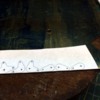
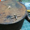
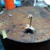
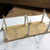
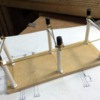
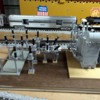
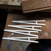
Spent some time out of the shop working on CorelDraw to detail the disconnector mechanism. I'm going to cut some bell cranks out of brass that will lie below the insulator bases. If I fabricate it right, it should actually be operational.


Disconnect Mechanism


I've come to a conclusion about what industry to feature on the railroad... a bourbon distillery and rick house. My daughter lives next door to the owners of a large distillery in town and we've become friends. I can get some good details on construction and should make a neat and interesting addition. I bought some grain cars at Roundhouse Trains yesterday to begin the process. N #2 grandson thinks it ought to be built right in the town. He said, "people would like to visit, so why not put it where they can get to it." I like his reasoning. I have lots of vacant space in town.

Attachments

Images (1)
  • Disconnect Mechanism

Started building the operating mechanism for the disconnecter. After printing out the drawing and sticking it to some brass sheet with 3M77, I located all the holes and drilled them while the drawings were still attached to one big piece. I then cut them out using a jeweler's saw. This went pretty well. 


Disconnect 10


Disconnect 11


After cleaning up all the edges with the belt sander, files and sanding sticks, they came out decently.


Disconnect 12


Here's where things started getting dicey, before completely screwing up.


To attaching the moving rods to the bell cranks, I chose to solder 0.032" brass rod to the plates with the small holes, 


Disconnect 13


then using the small spacers that I produced on the lathe from some small diameter brass tubing, I trimmed the pins to the same .052" height. I assembled the pieces together and then attempted to solder the blank up plate. My idea was to have the upper plate capture the rod onto the pin so it wouldn't fall out. Everything went swimmingly until the very last piece. I was using the resistance soldering unit to apply the heat. 


Disconnect 14


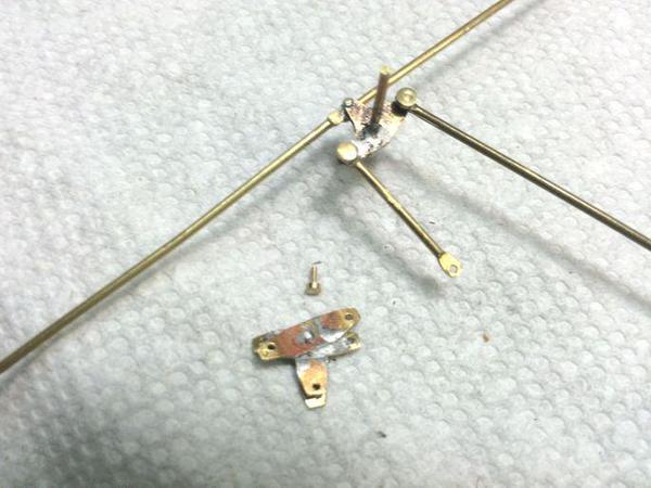
And here's what it all looked like when things starting hitting the fan. First, I couldn't get the solder to behave to attach the bottom plate to the shaft. When I picked up the unit to look at it, the bottom plate along with all the rods, fell apart. Then one of the eyes on the long bar broke from the center bell crank, finally it all came apart.
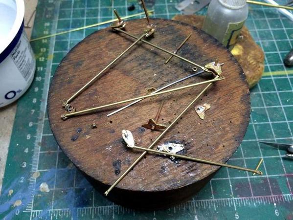
 

Disconnect 15


With this failure, I'm rethinking the engineering. First of all the brass is too thick. It scales out to almost 2 inches. I bought some .015" brass sheet today to remake the bell cranks. Next, soldering the pins on one side and attempting to put a blank plate on top to contain the rods wasn't good. The pins should go through both pieces. Lastly, the center large bell crank actually blocks 90º rotation. At best it gives 45º. To correct this problem I need to separate the right left rods from the fore and back rod and mounted on different planes.


So here's plan B. I'm going to solder two thicknesses of brass together, and drill and cut them at the same time to ensure that everything lines up. I will then Solder the tops and bottoms together with the spacer and center shaft, and then install the rods and pins. The pins won't need to be soldered at all. I'll just pinch the pin that extends out of each side to make it so it will no longer fit into the hole and then trim of any excess. This will allow me to do all soldering without any moving parts in the way.


If this doesn't work, plan C is to simulate the whole affair with styrene.


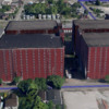
On another topic. I'm going on a private tour of the Heaven Hill distillery in southwest Louisville on Friday. I went on Google Earth to get some aerial pictures of this installation. It's not a very big plant and could work well with selective compression. Heaven Hill Bourbon has two installations. The distillery with some old aging houses in Louisville, and a very large barreling, aging and bottling facility in Bardstown, KY. The Bardstown bottling plant is 1,200 feet long by almost 800 feet deep. In O'scale, that's 25 feet long, by 16 feet wide, and that's just one building. So I'm staying away from that.

 Heaven Hill Distillery Aerial 1

You can't see the storage silos in the above picture. There are 6 big ones that are about 25 feet in diameter. They could be shrunk in size and I wouldn't need 6. My trip on Friday will certainly help me in understanding what can be done in my scale and what should be left out.


This picture shows some old aging houses in Louisville. These are big. They're too big to do in scale and I'd only make one of them. They look like brick structures. In Bardstown, they're corrugated metal siding covering a very large timber structure. Building a "rick house" is an art in itself. They entirely constructed of very heavy oak timbers and the rack assembly is independent of the roof and side walls. They hold immense weight. 
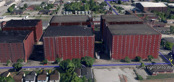
Heaven Hill Distillery Aerial 2


For example, a loaded bourbon barrel weighs almost 500 pounds. One rick house holds 42,000 of them. Heaven Hill has over 1,000,000 barrels in storage. 42,000 barrels weighs 21,000,000 pounds. There is plenty of air flow through the building since there is constant evaporation of alcohol vapors out of the barrel. There's no ignition sources allowed anywhere near these buildings. A 20 year-old barrel of bourbon in storage loses about half of its liquid.


Imagine trying to plan for a business where your product has to sit in inventory for 8 or more years before selling the first bottle. With bourbon undergoing an international boom (helping both Kentucky and Heaven Hill) they can't produce enough, but alcohol you distill today can't be sold for a decade or more. It's a tough business. The empty barrels cost about $42 a piece. Imagine 50 million dollars just tied up in the barrels. When they're used, they are sold to the scotch industry for aging.


I'm sure that's more information than you've asked for, but it's good for us railroaders to understand the industries on our pikes and what infrastructure they would need to thrive. Modeling any large industrial facility in O'scale is a challenge. Just ask the guys building petroleum refineries and steel mills. A bourbon distillery has lots of interest having some food industry and chemical industry aspects. They are served by railroads especially to bring in raw materials. Heaven Hill has their own tractor-trailer fleet for delivery.

Attachments

Images (8)
  • Disconnect 10
  • Disconnect 11
  • Disconnect 12
  • Disconnect 13
  • Disconnect 14
  • Disconnect 15
  • Heaven Hill Distillery Aerial 2
  • Heaven Hill Distillery Aerial 1

My mechanisms could be better... especially if they worked. I tend to over-engineer. Speaking of over-engineering... we all praise German engineering, but they too over-engineer. While living in Germany, our house had these very sophisticated large windows. If you turn the handle 1/4 turn, the window would open inward from the top. but if you turned it a half-turn, the window would open fully from the side. In addition to this, the window had all sorts of cams and latches that would lock it closed. Very engineered. It took burglars 15 seconds to break into such a window. Just because something is highly engineered and complicated doesn't make it better. It's all about function. I hope my second design is better.

I redesigned the bell crank mechanism for the front unit(s). This is made of much thinner material and will require some bending, but no spacers and should be easier to solder in one go.


Disconnect Mechanism Rev 1


The rods are staggered so they won't interfere with one another. I won't be able to get to this till next week. Tomorrow I have a retina checkup resulting from getting flashing last year, and Friday is the trip to the distillery. I may have time Friday afternoon when I get back.


I visited the maker's room at my grandson's school today. I'm offering my time as a mentor. They have a 40W Full Spectrum Laser engraver/cutter and a Makerbot 3D PLA plastic printer. It's the rebirth of Industrial Arts Education which has almost died in the USA. I graduated as an Industrial Arts Teacher from Michigan State University in 1968. At that time, we had an entire wing of the Education building with all the shops represented. In 1985, when I had the opportunity to visit again, those rooms were already vacant and the program no longer existed. In other words, the US was losing the desire to teach kids to make things already. This was long before the cry about the US losing manufacturing jobs. The canary was in the coal mine and it already was dead.


Finally, some folks are beginning to realize that not everything can be done in a virtual world. At some time folks actually have to make something. I am very excited about being able to help in this effort. As a side benefit, I'll be able to do some model work with those amazing machines.

Attachments

Images (1)
  • Disconnect Mechanism Rev 1

I fabricated the redesigned bell crank today. It came out as planned, but unfortunately my plan wasn't exactly right. I still can't get the range of motion I need on the rods. I'm going to stop working on this aspect, make it a fixed detail and get on with the rest of the disconnector. I've got a lot of stuff to do and build and can't get too bogged down on a detail that really won't ever be necessary.


I also had that plant tour of the Heaven Hill Bourbon Distillery in West Louisville. It was an excellent tour and I took looks of pictures. This project will be so comprehensive that it deserves it own thread, so I will now start that thread to run concurrently with this one on the substation.


I made the new bell crank out of three formed pieces of .015" brass stock. I bent the offsets, then drilled the .047" center hole so I could put a rod in them to align and hold them. I used the RSU and TIX solder and got a solid job. I then drilled the .032" holes through both sides of the clevis and got nicely aligned holes. 


Disconnect 17

Disconnect 16


After cleaning them up a bit, I attempted to assemble the rods in the clevises along with the brass pin. I had to reshape the rod ends a bit and clean out the clevis from some excess solder and got the pins to go through everything. The problem with range of motion lies in the clevis blocking the rod from rotating inwards. This greatly limits the amount of travel and makes the opening and closing of the contact arms an impossibility. I suppose I could go back to the "drawing board" and do another go around, but frankly, it's totally unnecessary. 


Here's all the pieces assembled.


Disconnect 19

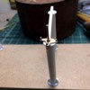
I started preparing the insulators that will go on top of the rotation mechanism. I'm using a different Hillman auto body fastener for this one. It will take 3 insulators per connector arm. I have to cut one in half to make one segment, then there will be a turned piece and another 1-1/2 plastic part to make the other segment and then the top fitting with the disconnector arms. I'm going to make the arms out of square brass tubing so I can solder the various fittings and arc extinguishing pieces.


Disconnect 20


I have to buy more of this style to finish the job. I don't foresee any more complexities, but then I can be wrong. I know I have been very wrong in the past.

Attachments

Images (4)
  • Disconnect 17
  • Disconnect 16
  • Disconnect 19
  • Disconnect 20

Behind our entertainment center was a horrendous rat's nest of cables which my wife hated to look at. In our old house, it was in a location that you really couldn't look behind. In the new house, it was there to be seen every time we went out of the house or into our bedroom. We bought a ton of organizing stuff at the Container Store in Cincinnati, and I got to work on it. Needless to say it was difficult work, we had plenty of very "passionate" discussions and I finally did it. It took three iterations and over five hours of work. 


Before:

Wires Before

 After:

Wires After


So, you may ask, "Why am I telling you all this?" Here's why. One of the most cogent arguments my wife was making when I made a first—and unsuccessful—attempt was "How come you work on stuff with your trains over and over until you get it perfect, and yet on this you're trying to pass off a sub-par job?!" (those weren't the exact words, but you get the idea. Bob might redact the actual words). It was a good argument, which I didn't like very much and it hit home. So I did it over two more times until the final result. Well folks. She's right. I do keep doing stuff over and over until it meets a high standard. And that's what happened in yesterday's session.


I was unhappy with version 2.0 of the bell crank mechanism since it was still blocking full rotation and therefore precluding any mechanical fidelity to the real disconnector. So I went at ver. 3.0.


What was really needed was a pin system that didn't protrude to the underside which kept limiting movement. I machined some small (really small) brass pins that would captivate the rods. While machining the pins, I also machined all the other bits that would make up the insulator stacks.


Disconnect 21


The pin diameter is 0.031"; the head size is nominal and doesn't matter very much.


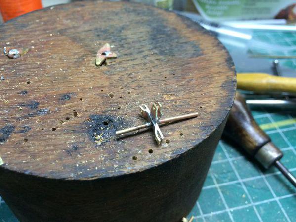
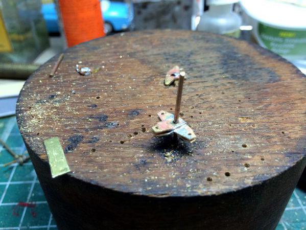
I attempted to solder the pin in place holding the rod without soldering the whole deal together. This work...sort of...in one instance, but ended up soldering the rod to the pin in the other two. I ended up riveting the pin on the other two. It still needs some more work. 


Disconnect 22


I was able to use the bell crank plate from Ver 1.0. Along side you can see the remains of Ver 2.0. The expanded pins on the two auxiliary arms are sticking down into the path of the long rods and is blocking their motion. I'm going to try and fix this a bit.


Here's the range of motion with the new design.


Disconnect 23-1


Once again the picture was flipped. I didn't take the pic upside down.


You can see if you look closely that it's getting something less than the desired 90º rotation. If I can flatten the protruding pins that might work. Now... the real way to make this correctly, IMHO, is to make some shoulder screws that are threaded into the bell crank plate. With a little Loctite on the thread, and filing the protruding threads on the bottom, the unit would work exactly like the prototype, which from the pictures seems to have ball-end connectors a la RC air craft servo connections. To this end, I've just ordered a set of jeweler's taps and dies that will enable me to make such miniature specialty screws. My wife was right, I don't give up until I get it like I want it.


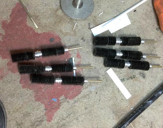
After working on the mechanism, I spent some time building the insulator stacks. They consist of 1-1/2 Hillman auto fasteners in each section, with the aluminum turnings in each. This style of insulator doesn't have ejection pin blemishes or the missing segment like the bigger ones I used on the Xfrm, breaker of CCVTs, but I do have to cut them to make them work.


Disconnect 24


The insulators look very good with almost the right profile for the water shedders. Here's one stuck on the rotater mechanism.


Disconnect 25


I'll finish these today and get working on the actual disconnector electrodes. This is getting near done.

Attachments

Images (7)
  • Wires After
  • Wires Before
  • Disconnect 21
  • Disconnect 22
  • Disconnect 23-1
  • Disconnect 24
  • Disconnect 25

Spy camera...


After messing around with the bell crank one of the holes broke out. It wasn't centered in the piece of brass. Since I had to remake the whole deal it gave me a chance to attach the pins by riveting them, instead of crushing them in pliers.  I also found that the main crank was impinging on the cross beam.


Disconnect 26


Every time I crop a picture, this website turns it upside down. Doh!


I made a new bellcrank, and machined some more pins. One of the other mechanisms let go and I remade that one also. I ran out of the small brass rod and had to make lots of chips when carving down a big piece to 0.030" pin. I used my new Tap Matic brass cutting fluid to make the cuts nice and smooth. I used the cut off blade to do this by just plunge cutting in a series of bites until getting down to the finished size.


Disconnect 27


I again reassembled the whole affair and got pretty good range of motion. If I were to refine this further—and I'm not—I'd redo all the rest of the cranks and make them with the riveted pins.


Here's the new bell crank. If anything, it's certainly prettier.


Disconnect 28


This took a lot longer than I wanted. I lost at least two pins into the Quantum Rift. Seriously, I swept the floor twice and they were gone. So it was back to the lathe to make more. I got pretty good at making them. When I get my watch maker's taps and dies I'm going to experiment actually making my own miniature screws.


I did get the rest of the insulators made.


Disconnect 29


The last bit that needs to be done is the contact arms themselves. There are these aluminum plates that lie one over the other that serve to manage the arc on separation. I was planning on making the bars out of brass so I could solder thin brass supports to hold the aluminum arc management plates. Then I'm left with CA'ing the plates to the brass. I could make the plates out of brass and solder them too, but I would like to have the natural aluminum showing. It, like the bell cranks, will probably take multiple tries to get it right.

Attachments

Images (4)
  • Disconnect 26
  • Disconnect 27
  • Disconnect 28
  • Disconnect 29

Today started work on the disconnector arms themselves and the arc horns that attach to them. I also decided that another bell crank assembly needed to go the pins/rivet method which I'll do next session.


The arms are made of 1/8" sq. brass tubing, with the .047 holes drilled in them for the pivot shaft. The piece was measured from the distance between the poles and the pivot holes were picked up from the hole spacing in the base.


I cut them in half on a 45º angle with a razor saw and miter box, and then soldered a large copper plug into them on both sides that would act as the contact. That clearly was overkill. 


30Disconnect 30


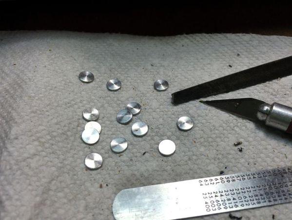
The arc horns on these units are aluminum discs that are about 1 scale foot in diameter. I measured them on the plans at about .030" thick. I turned a stick of aluminum on the lathe and then parted off 14 of them at the right thickness. I use the digital caliper's depth gauge end that sticks out the other end of the bar as a precise gauge to set the longitudinal feed on the lathe. Someday, I outfit the lathe with some direct reading dials or digital readouts. There's stuff on YouTube showing how people did this. After parting about halfway through, I took a Swiss needle file and slightly rounded both edges and then finished parting them off. A file was need to remove the little nub that remains on the cut side.


30Disconnect 29


These will be CA'd to the arms. One side has them mounted on a some brackets that space them away from the arm, and the other has them mounted directly on the arm so they pass under and over each other when the arms are connected.


To make the brackets I used some left over fret material from photo-etched parts. It's very thin brass that;s not too soft. It makes great stock for small sheet-metal details. Don't through it away! To solder them on I first tinned the arms with a tiny piece of solder on a fluxed portion of the arm near the middle.


30Disconnect 31


A couple seconds with the RSU and the solder melted. A nice thing about the resistance unit is that it's always ready for use. It's only hot when you hit the foot pedal, and it's instantaneous. I only use the Weller soldering station for electronics work these days.


I formed the brackets, added a little TIX liquid flux and used the tweezers on the RSU to hold the bracket onto the tinned area on one side. A few seconds on the pedal and the pieces were fused.


I then held the bracket for the other side, used the RSU tweezers to hold both brackets to the arm (the previously soldered one and the new one) and again, in a couple of seconds the new bracket was on and the previous one was still there.


30Disconnect 32


I then CA'd the completed arms to the insulator stack.


Disconnect 34


Upside down again. I was going to paint the arms before fixing them to the insulators, but decided against it since I wanted to CA to bare metal. I'll mask the insulators. I will be putting the arc horns on last since I want them to be natural aluminum. The arms would be more securely attached if they were soldered. Unfortunately, since the insulators are plastic, the soldering heat would wreck them. If i was to do this again—and I'm not—I would have soldered the arms on first, then assembled the stack. Live and learn.


As it stands now, the disconnect mechanism could actually work. I have no earthly reason for doing this other than it's just cool. I may be able to pose the station energized or de-energized. It was more just a self-challenge to see if I could do it. To make it just a static model, the whole deal could have been polystyrene like the transformer.

Attachments

Images (5)
  • 30Disconnect 30
  • 30Disconnect 29
  • 30Disconnect 31
  • 30Disconnect 32
  • Disconnect 34

Lee... you are too kind. It's kind of funny... when I was laid off in 1986 (training folks get laid off about every 6—8 years depending on the business cycle—I was given out placement. In that process we were given occupational aptitude tests. Mine showed that I should be a model maker in the movie industry. Clearly, I'm just doing was I was destined to do, except I'm not getting paid for it.


Today, I rebuilt the last pieces of the operating mechanism that needed to be replaced using the rivet method that seems to be working pretty well. It's still not optimal. I started preparing everything for final assembly, and began building the little control box that would (in the real world) provide the impetus to open and close the contacts.


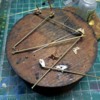
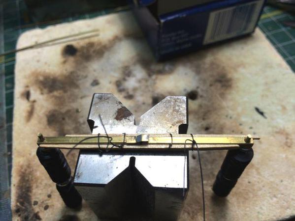
In order to keep the contact points aligned and set up the spacing as they wait to be epoxied in place, I made splints using tooth picks and iron wire. This is holding them in their final position so the epoxy can glue them in proper registration.


Disconnect 35


Since the mechanism is now as complete as I'm going to make it, I epoxied the bottom supports in place along with some spacers on the newly re-engineered ones since they are only one layer of brass instead of two like the original design was. 


Here's all of that curing with the three sets of contacts waiting their turn.


Disconnect 36


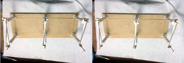
Not ever seeing the machine operate, I didn't know how the contactors separate. Did they open in opposite directions or in the same direction as a double door would. To make it go opposite, the bell cranks are set up like the above. To make them open together, the rods would cross over the other side. After playing around with it, I decided that you'd get faster and wider separation by having them open opposite to each other.


I started building the little control box and installed a tubular cross-member between the center posts. The little box is just a smaller version of the one used for the breakers.


I got some new tools today. I found an Internet jewelry supply where I could get larger quantities of specific jeweler-sized drills. I bought 3 sizes that correspond to those of the three sizes of brass wire that I always use. I also sprung for a jeweler's tap and die set for really small screws from 2 mm down to .7 mm. This is for future projects that are going to have moving parts where I really want to do it right. I need to find information of what size holes and rod diameters are needed to cut these very small threads. As I said before, the ideal way to have made that contact mechanism would be to machine miniature shoulder screws that would be threaded into the bell crank.
 

Jeweler's Taps


I am sure I will break those small ones the first time I try to use them. I find that using Tap Magic really makes cutting the small stuff much easier. It was a snap to make those 0.031" pins.

Attachments

Images (3)
  • Disconnect 35
  • Disconnect 36
  • Jeweler's Taps

I know the SVP of the power equipment company at ABB and sent him a link to this thread.  I think it is fantastic work.  I suggested maybe they look at them for an article in the employee magazines.  I have no idea if anything will come of it. 


It is often a mistake to turn a hobby into a job (actually, is is seldom anything but a mistake to do so) but I am certain that, well-marketed, you could sell these for some very pretty pennies, Trainman 2001.  They are just fantastic. But if it were me, I wouldn't, just make them.  

Yes, a hobby can quickly turn into a job.  I was given this piece of wisdom from my dad when I was in my 20s.  Dad, now 84, is an avid fly fisherman and fly tier.  His flies still are impeccable.  He can fake out all but the oldest wiliest trout.  Back years ago, I asked him why he doesn't sell flies to Orvis.  He has always had to pinch pennies, and Mum is a master at it.  His still are as good as the ones they sell.  He told me then there would be quotas and deadlines and it would no longer be a hobby to relax from a hard days work.

Mark, I think your father is right. I built models on commission back in the late 70s and 80s. It probably works out at pennies per hour salary. When I built the B-17 several years ago, I made the deal for $600 with the owner providing all materials. It ended up taking 13 months and I think I made $0.60 an hour... not enough to do anything except maybe buy modeling supplies.


It's always a temptation to build for fee, thinking that it would feed the habit, but often it ends up in not working on the projects which got you into the business in the first place. I just advised a young colleague who was thinking about making custom, high-quality furniture as his vocation, that making a piece that sells for $5,000 must be repeated 20 times in a year to provide a living wage after expenses. I suggested, he do like Mark's father, build furniture for his own enjoyment, and if he sells something at one time or the other, take your family out to dinner to celebrate. Otherwise, you have to get on the Art/Craft show circuit and that's not fun.

Last edited by Rich Melvin

Trainman,

Yes, this is a lesson our artist daughter who is still living with us is learning.  Every art teacher or professor she has ever had said she has tremendous talent.  How were we to do anything but encourage her to make the most of God's gift to her in college studies.  She has run into just the situations you have mentioned, and is frustrated with her low sales.  To make matters worse, we don't have the space she needs for a full art studio, and she can't afford it herself.  Coupled with some physical problems and a stubborn personality, we all live in frustration.  Her boyfriend of 7 years graduated with a degree in graphic arts and is working at a local convenience store, not finding work in art so far either.  It took a long time for his sister, also an artist, to be able to make her art profitable, but she had to wait until her son was in high school, and her husband advanced to the point he could carry all the family bills.  I don't know how to apply Pap Pap's wisdom to their situation, but it is a learning process every young adult faces in some form or another.


Back to the P&PRR power substation construction!!  

Last edited by Mark Boyce

I'll digress just a little bit longer...


My nephew is 45 years old. He's a very creative and terrific artist. His work is installation art. Large structures you interact with that use lighting and music which he creates himself. He's been waiting for "His big break" for 20 years. Each deal is the one that's going to do it. It hasn't. Meanwhile, my brother in law, who is a successful pediatrician, and is 80 years old, keeps supporting him and is fed up. He claims he can't retire because of the son's dream. I'm sure there's some truth to that, but I also don't think he wants to retire regardless. Meanwhile, my nephew is living out my sister's dream. She wanted to go into the arts, but it was the late 1950s and my parents had other ideas. It's a tough life, and like going into professional athletics, a few make it really big and the rest don't. Just thank G_d that we live in a country and age where our loved ones can chase their muse without having to work in the fields, or get drafted. I've counseled my nephew many times hoping to get him to go into a professional that can pay him a living and then work the art at the fringes, but he insists that he has to devote all his energies to it. That's life. Good luck to you and your daughter. Now I'm going into the workshop.


Last edited by Trainman2001

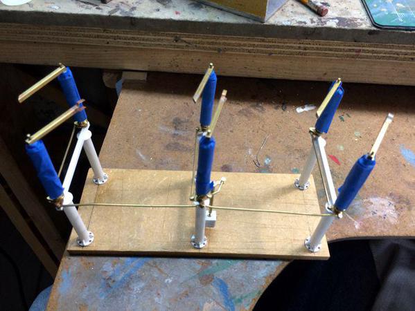
Epoxied the contact arms and insulators to the rotating mechanism, and then went back to building the control box. The mechanism works...sort of. As this movie shows, the arms do move in synchronicity. But... the angle cuts I made to the contactors are now wrong. They were put that way when I was planning on having the arms move off in the same direction to the right. When I changed the scheme so they would move apart in opposite direction, the angles were now backwards. The arms can't engage properly. The arms are glued to the insulators with CA and can be broken loose with some friendly persuasion. I turn them over and the angles will be in the right orientation.


Here's the assembled unit.

 Disconnect 38


This shot shows the backwards angles. 


Disconnect 39


The control box is now done except for the door handle. After I took this picture, I glued on some styrene angle that will support it when attached to the cross member. Also not shown is the vertical shaft, the new operating lever, and the outer brass tubing jacket. I'm in the process of machining as brass bushing to support the operating shaft more securely than just sitting in a hole on top of the control cabinet. One or two more work sessions should finish this up. I'm going to seal the wood base prior to painting it "concrete", and masking the insulators so I can air brush the rest, Tamiya Sky Gray. I may use a coat of Krylon primer first since it holds onto metal better than the Tamiya acrylic.


Disconnect 37

Attachments

Images (3)
  • Disconnect 39
  • Disconnect 38
  • Disconnect 37
Videos (1)
Disconnector

Thanks AG! I attempted, vainly, to remove an arm to be able to turn it around so the angles can let the arms open and close. It didn't budge and I wasn't going to wreck anything. I could grind the angles off to let the arms clear each other, or just fasten them together and leave it as a static model. I really won't be able to operate those arms once it's on the layout anyway.


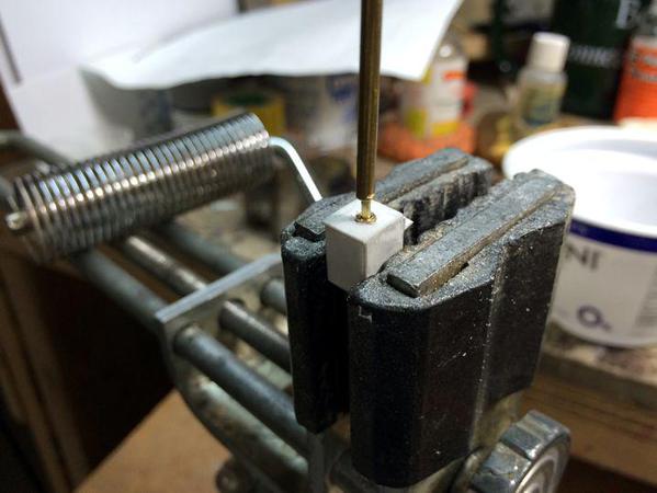
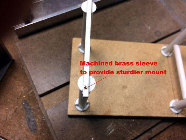
I finished the control box by machining a little bushing that's inserted into the box top and allows the operating shaft to turn and be properly aligned. This worked so well that I made bushings for four other locations where the bell cranks attach to the frame.


Disconnect 41

Disconnect 40


The cross arm is just .108" wide and the pin is 0.047", so there wasn't much plastic to work with when I enlarge the holes. I made the bushings 0.070" with a 0.052" hole. 


The box was solvent glued to the cross piece and the operating shaft dropped in. I had to bend the bell crank link so it would align properly with the shaft's crank end. I machined another pin. Since there was a slight elevation difference that needed to be matched, I also machined a small spacer with a 0.047" hole. The excess pin that was hanging out was squeezed with the needle nose to deform the end so it wouldn't pull out.


Disconnect 42


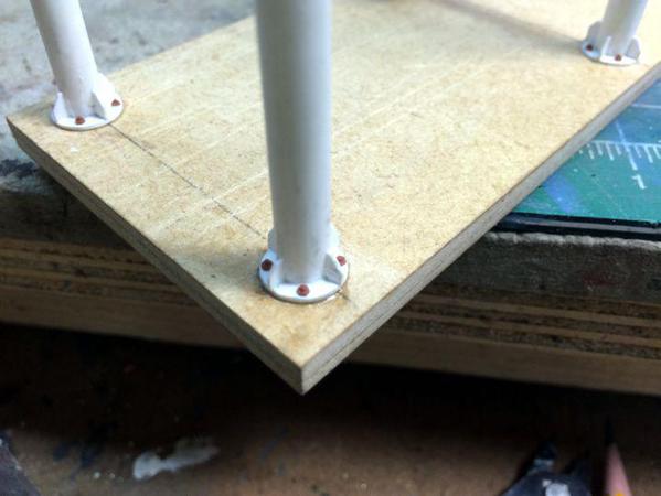
The last bit of detail was some Tichy NBWs to "fasten" the posts to the "concrete".


Disconnect 43


I don't have any sanding sealer, so I sealed the Masonite base with some Testor's Dullcoat lacquer to it wouldn't absorb the acrylic paint that I'm going to use to simulate the concrete color. And the last step was masking the insulator stacks in preparation for painting which I'll do tomorrow.


Disconnect 44


I couldn't help myself... I stuck the unit onto the substation base to see how it looks.


Disconnect 45

Attachments

Images (6)
  • Disconnect 41
  • Disconnect 40
  • Disconnect 42
  • Disconnect 43
  • Disconnect 44
  • Disconnect 45
Last edited by Trainman2001

Trainman,

It reminds me of my days at Virginia Power!  The most realistic power substation equipment I have ever seen by far!!  Thank you so much for taking us through the process!  You are certainly a craftsman extraordinaire!!  It is so realistic, when you had the substation worker posed by the cabinet, I could feel the shock from the time 25 years ago when I got nailed with 220VAC as I related at the time.  This is certainly lower voltage equipment but I remember static was so high in the 500KV stations, that if you didn't wear a glove opening the cabinet door the static would eat you up!  I could hear the static crackling as soon as I got out of the van to open the gate.


What are you going to use for buswork and for a fence and gate?

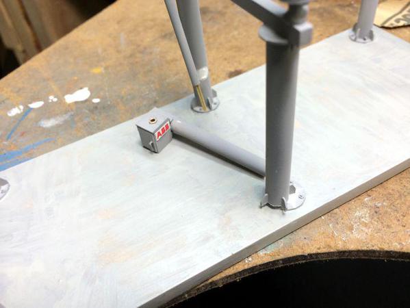
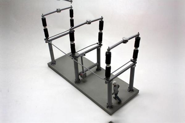
Well... if you liked that take a look at this. I put it all together today, air brushed the gray, added the ABB logo, and painted the concrete base. While I was handling it, this happened.


Disconnect 46


It was the result of I think two causes. I think the cross member was a tad wide... I mean 5 to 10 thousandths wide, and was putting pressure on the pole base. Then I was using a paint that uses acetone as the solvent. The vapors may have penetrated the base to pole joint and I was holding onto this center support while painting and "Crack", the base broke loose and then the cross member. Luckily, styrene is forgiving. Before rebuilding, I sanded a bit more of the curvature to make the piece a bit shorter and then reglued and repainted the whole deal. I overcoated the concrete paint with some craft acrylic that I mixed using black, antique white, and some yellow ocher. It's not a bad mix. 


And then I took these.


ABB 3-Phase Disconnector Finished 1 sm

ABB 3-Phase Disconnector Finished 2 sm

ABB 3-Phase Disconnector Finished 3 sm

ABB 3-Phase Disconnector Finished 4 sm


As you can see, I CA'd the arc extinguisher disks to the arms. The little brass brackets worked perfectly. CAing metal to metal is always a challenge. Sometimes it seems like it's fully adhered and then you touch it and it fall apart. I find when that happens it's best to scrape off all the hardened CA and start all over. Otherwise, you get buildup and the piece has even less surface contact area upon which to adhere.


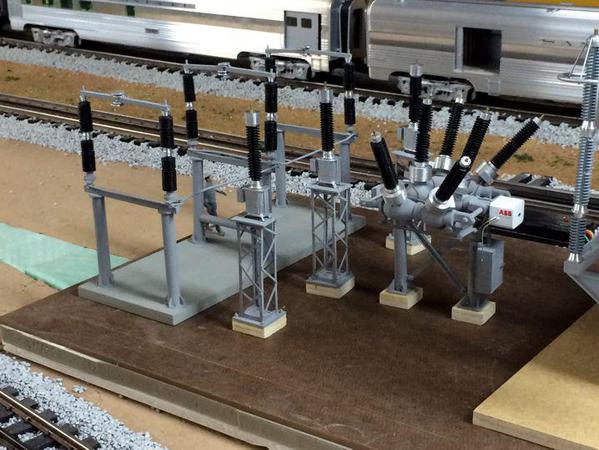
Again, I plopped the disconnector onto the substation base and took some shots.


Disconnect 49

Disconnect 48

Disconnect 47


With the disconnector complete, the HV equipment section is complete. Next up is the gantry assemblies that will bring HV into the station. And then it will onto the low voltage secondary section. In many installations, the transmission voltage, (10 to 12.5 KV) is then run into cables and run under ground. I don't know if this was done in the 50s. I highly doubt it, but neither did the transformers, breakers or disconnects look like this in the 50s, so I'm already mixing eras. I'm going to use small aluminum bars for the bus system.


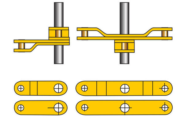
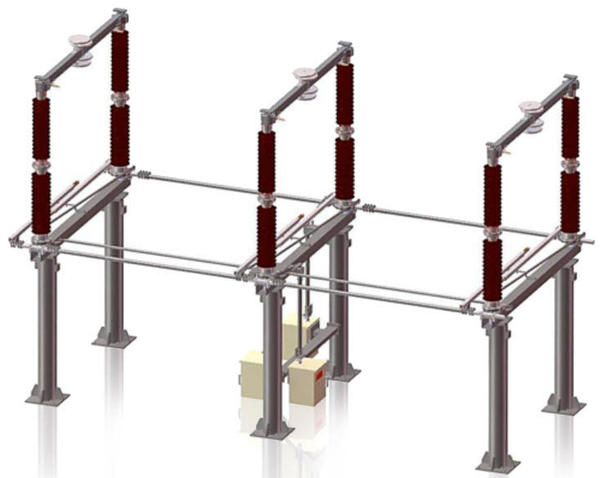
As a reminder, here's the drawing from ABB's literature. This unit shows all the options available some of which I chose to leave off. Those smaller horizontal rods flanking the cross members are "earthing bars" that swing down to ground the assembly when the circuit opens. It's an option on the real one and I chose not "buy it".


ABB Center-Break Disconnect Illustration


On another side-bar... I use a Logitech Track Ball Mouse that has this big, red plastic ball that you roll around with your fingers instead of the thumb. It regularly falls off the arm of my easy chair and the ball pops out and rolls all over the place. I've had two others before. Sometimes, the impact of hitting the floor forces the little spherical pad into the bar and puts a ding it in. This ding then gets caught on the pads periodically and jams it momentarily. Well, tonight I decided to attempt to fix it. I found the ding, sanded it down so there were no raised edges and then filled it with a tiny drop of thin CA. When cured, I sanded it flush using a 400, 600 and 800 sanding stick and then polishing compound. The ball is now smooth and is fixed. Taa Daa!

Attachments

Images (9)
  • Disconnect 46
  • ABB 3-Phase Disconnector Finished 1 sm
  • ABB 3-Phase Disconnector Finished 2 sm
  • ABB 3-Phase Disconnector Finished 3 sm
  • ABB 3-Phase Disconnector Finished 4 sm
  • Disconnect 49
  • Disconnect 48
  • Disconnect 47
  • ABB Center-Break Disconnect Illustration
Last edited by Trainman2001

Yup! That's right! It's O'scale and I can set whatever era I want and even mix them. If any of you watch "Gotham" on Fox, you see anachronisms all over the place. It's supposed to be the 60s, based on the cars they're driving, but there are computers all over the place. It's like that.


Besides, 1950s era substations had black painted equipment and all the gantries were fine lattice that is very difficult to model, or expensive to buy if you go the Plastruct route. I may use some more lattice on the low voltage just to mix it up a bit. There's a modest-sized control room that will be built by traditional methods unless I can get some stuff laser-cut. I wish the prices on those were dropping as quickly as they are on 3D printers. It's that CO2 laser tube that adds to the cost.


As I look at the pics more, I'm thinking that I'm still not getting the concrete color right. It should be a bit lighter and have more tan in it. It now looks like fresh wet cement. I'll keep working on it before I paint all the other concrete parts. If anyone has a mixture formula I'd be happy to hear about it.

Last edited by Trainman2001

Well, I just got the word from the project manager that work has commenced on the civil work in the substation. I'm using 1/4" H-beams by evergreen. These would be a scale foot wide... maybe a bit big, but they'll work and it's the size I used on the plot plan.


My angle cutting came out a little too shallow on the first piece I did and I used that as a template for the remainder. I suspect that since these towers aren't going to support any switchgear, that the narrower leg stance won't be a problem. I scored the angle with a single-edged razor and broke the piece off at the score line. I sanded the cut line so it was truly flat and then used solvent cement to glue the legs together. When this set up, I measured and cut a single reinforcement piece. For the angles, I reset the fence on the Precision Sander and put the angle on both pieces. It's the same way I did the truss angles for the bridges project.


HV Gantry 01


I then reset the fence again so I could sand the bases of the H beams so they would properly sit on the base plates that will be glued on next. I also sanded the top joint flat and level.  


HV Gantry 02


I've found some problems with the Touch-n-flow glue applicator. The plastic and the solvent cement seem to have opposite static polarities. Sometimes the drop at the end of the capillary tube simply jumps off the applicator and hits the plastic WHERE I DON'T WANT IT. Add to that my unsteady hands (hadn't had lunch let an blood sugar was down) and there's glue where I don't want it. I sanded off the high stuff, but I'll use a touch of Sovereign Green model putty to level it all out before painting.


Oh, I also cleaned up the work area before starting this next phase. I got word today from O'Scale Mag that there is the intent to publish the next phase construction article. I'm hoping to do a long-running series on the entire substation build.

Attachments

Images (2)
  • HV Gantry 01
  • HV Gantry 02

I'm very happy to please. It's a lot of fun for me to. And if I can keep publishing the articles about it, the project could actually turn a profit. Life is Good! Now that the really hard parts are behind me, it should be easy sailing... "Other than that Mrs. Lincoln, how did you like the play?" "Pride goeth before the fall." Bending the bus bars so they work as they should could be more trouble than I anticipate.

Originally Posted by Lee Willis:

For me, this is one of the best projects ever described on these forums.  I look forward to it each day.  Wow!  This is fun!

Well, it's certainly going to be one of the most detailed modeling jobs I've seen, it's amazing how much work it takes to make something like this!  Your RR will certainly have sufficient power once the sub-station is completed.


Thanks Gunner! My big industry is the planned Bourbon operation... They consume a lot of steam, but don't have too much in the way of very high HP motors. Now if I was building a low density polyethylene plant, now that's a different story. In the early 80s, I was the training coordinator for ARCO Chemical. They had a plant in Port Arthur, TX that had a very large shed filled with hyper-compressors (50,000 psi) and each was powered by a 5,000 hp synchronous motor. Now that was a power load! They also had one powered by a uni-flow reciprocating steam engine built by Ingersoll Rand. I loved being around that stuff.

Add Reply

Post

OGR Publishing, Inc., 1310 Eastside Centre Ct, Suite 6, Mountain Home, AR 72653
800-980-OGRR (6477)
www.ogaugerr.com

×
×
×
×
Link copied to your clipboard.
×
×