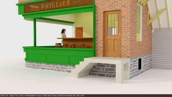
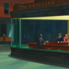
I love the look of the turret in Trainman's model.
Thank you all! I've always liked city buildings with turrets, although I never know what they're actually for. It would of been much easier if I didn't actually want that room usable since it was a real pain to build that angular hallway.
More window work today, and it was a pretty long session so I got a lot done. First up was gluing the front panel to the bottom of the lower sill. I first glued on the former aligning it by eye as best I could in the apex of the curve. I used thick CA to hold it. I then glued some 1/8" sq. styrene along the glue line to support the extremis of the front panel. I used solvent cement and then followed this up with thin CA for a more secure junction.
I tried the window in with the panel.
The window glazing itself is just about 1/8" proud of the building wall so I boxed it in with some 1/32" ply. I'm not sure if this is actually ever done this way, but I couldn't push the window in deeper without doing MAJOR surgery.
It was time to finish the panelization of lower panel. I used a combination of 0.040" X 0.188", 0.040" X 0.125" and 0.040" quarter round trim. The upper rail was the .125 stock as were all the verticals. The bottom rail was the .188. I used the quarter round to trim between the top rail and the sill and on the bottom edge.
After putting in the extreme verticals, I estimated where the curve began and put a vertical on one side. I then measured this distance with the caliper and spaced off this distance on the other leg so the middle verticals were somewhat centered. I then divided the space between these verticals in thirds and marked a line that was then squared up with a machinist square. This was the center line for the verticals. Since when I glued them on I would obscure this line, I then put a little extension of it on the upper and lower rails so I could get it right.
Here are the panels complete.
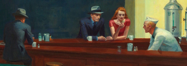
With the lower panels complete, I built the boards that would hold the Hopper "Phillies Cigar" graphic. I had isolated this image from his painting and then reworked the perspective so it was squared up. I cut the banner panels to fit from the building corner to the ends of the windows. This length measured 4.5". I then went onto the computer and sized this image so it was 4.5" wide. It looked a little bit skinny so I stretched the height a bit. I printed out a set of four on 5 X 7 glossy photo paper, but they were very dark, so I upped the exposure and reprinted them. This time the color felt right. I measured the exact height of the output image and used this to cut the banner panel height, plus 2 X 0.040" sq. stock that I glued on as a finished rim. I glued on the edging and tried it out on the building with a cut out Hopper graphic just put in place. I used final fixative for all my photo prints going into models to protect the inkjet ink.
All of this is going to be painted BN Green (Badger Model Flex) and since there's wood and styrene I took it all outside and shot it with Tamiya Rattle Can Gray Primer.
Before putting on the color coats, I needed this to dry completely, so I took the lull to start attempting to make the figures. UGH! This isn't going to be pretty.
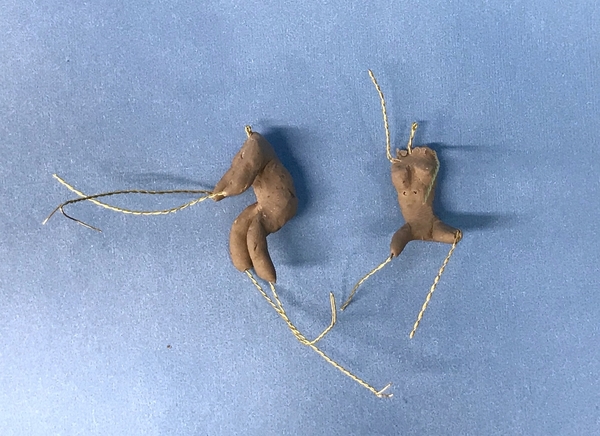
I made a wire armature with some 26AWG black iron wire roughly duplicating the size of an Artista sitting engineer figure. So far so good...
Then I started to wrap it with Sculpey. I'm using the standard Sculpey which is pretty soft. Too Soft! I got this far. And I'm really not very good at this...
The process SHOULD go like this. First you put a thin layer on the armature and then bake it at 275° F for 15 minutes which sets the figure's posture. Then you add another thin layer of clothing and fire it again. You keep repeating this until you have a respectable figure. The instructions that I found were terrific, but they were for making a figure in 1:16 scale where you can apply much more clay and therefore, have more strength. At 1:48, the armature wire is almost too fat so the clay keeps exposing it. You push it one way and it exposes on the other side, then push it back and it exposes the wire on the first side. It was time to start cooking the rack of lamb we had for dinner so I stopped before I had anything worth baking. Tomorrow, I'm going to try using Super Sculpey which is a harder clay what will hold shape better while working. The beauty of this method is you can harden each layer so you don't undo what you've already done. I have some lighter gauge wire I could try as well. I keep y'all posted… of course. As has always been my modus operandi… I show you stuff that doesn't work as it should as well as all the successful stuff.
Attachments
After just doing a tiny sanding job on the primer, I air brushed the window assembly and the banner boards. It took three coats with force drying in between to get the color solid. I un-masked it and then cut the other banner out. I applied the PSA to the boards and after drying, attached the banners to it. The banners required a tiny bit of trimming in their width to settle in flat. I again stuck all this stuff up to the building and took another picture. I also primed and painted a 3/32" piece of brass tubing that will be the ceiling support in the front corner of the room. It too appears in Hopper's painting.
You can see something that I hadn't realized when I glued the window into the groove. Due to the 1/8" thickness of the Plexiglass the bare wood in the groove is now showing. If (and it's a big if) I thought about this effect, I could have painted the groove before installing the window. That's bad. What's good is just how transparent the Plexi is. It will really show the interior perfectly. I wonder if I could flow some thinned green paint into the groove….?
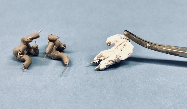
While this was all drying I got back to my figures. I removed the standard Sculpey and re-wrapped the black iron armature with the Super Sculpey which is a stiffer blend. It still looks poorly and the arms are too short, but I fired it and added some upper torso bulk. Meanwhile, I decided to try a different wire for the armature. I have this 0.010" brass wire netting that comes from the top of a bottle of Spanish Rioja wine. It's great detailing wire!
Here's the raw wire.
The wire is twisted together to make a net pattern. I proceeded to cut off a section and twist the remaining wires together in groups of two using two hemostats to hold and twist the wire.
I then turned this into a new armature.
Using the new armature I made a new figure. I left the extremities quite long and will trim them when I fully understand how long they should be. Both of these figures are baked at this point. I will use the standard Sculpey for the detail layers since it's easier to work. You can already see that I'm rowing up the learning curve. Since I have four figures to make I'll have a lot of practice. I think there's an Artista figure for the counter man.
Attachments
Short session today. We went to see the new movie about the capture of Adolf Eichmann. With the rise of far Right movements in Europe and here, people should see this movie to understand what true evil looks like. The rhetoric is repeating itself and the outcomes could also.
I started figure number 3. This is going to be Hopper's wife so I decided to actually model her body first and then add clothing later. I figured if I could get the bare (no pun intended) contours correct, then adding clothes would be less difficult. Meanwhile, I also added the arms and upper torso of the man's body. I'm concerned that it's already too thick and I haven't detailed any clothing yet. I think the female body is almost the right dimensions. It will probably take five or six of these trials before I get it right. With the figures baked and hardened I can go back with a sanding wheel to reduce any areas that are overly thick without distorting the rest of the clay. That's the beauty of baking the clay in steps so you can fix previous work and not worry about it.
While they were baking I started working on the two sets of exterior steps. They both have to be set off the building by the width of those end window boxes.
The outer contours are 0.040" sheet styrene. I want it to eventually look like poured concrete so the steps and side pieces will be glued and finished so it appears solid. I think I'm going to open up the space underneath the steps. This will increase the number of cross pieces that will have to be cut and installed, but it will make it more interesting and not so monolithic. I have some some laser-cut hairpin railings that I may use or I'll have to find some other PE or laser cut products out there.
I ordered some 30 gauge magnet wire to build some small LED exterior lights. I want a light over the entry door (the one on the right side) and a couple shining up on the banners. I can use the tiny surface mount LEDs and wired with magnet wire, they should make up nicely and not clunky. I show this later when the wire is delivered.
It's been a productive week, so everyone have a great weekend and enjoyable and stress free Labor Day!
Attachments
Saturday session. US Open is on and my wife has sympathy on me. I can watch tennis, but if there's something else more interesting, I'd rather do that.
I spent another hour fussing with those %_@*U% figures. The Sculpey does not like sticking to itself as much as I'd like it to. The wires keep protruding and I mess up as much as I sculpt in handling it. But I will persist. I would really like to see the man who run Artista do this so I could understand more of how to work in the small scales.
The magnet wire arrived today by Amazon from two different sources. I'm going to experiment in making some very small LED fixtures with it. Red is positive and green will be negative.
Lastly, I'm still noodling the design for the steps. Instead of making them a solid block of concrete, I might go with this. There, of course, will be a railing. Another possibility would be to make the solid step, but use the stone sheet that I used for the foundation wall. That would had some interest and be easier to build. The new design would involve a lot of cutting and fitting.
Attachments
Wouldn't the stairs be more prototypical built as a wooden platform supported by four 4x4 posts (maybe even 6x6) with a wooden stair stringer?
Not sure… This is an urban building like in Philly, and front steps in Philly were always stone or cement. And it's a commercial establishment. I think I'll actually do some research and find out what they should look like.
I can appreciate the trouble making the nightowls inside. You are right Artista has it down. My artist daughter hasn’t made any little people for some time to my knowledge! Her’s were always fantasy, but she had the knack!
Does she work on commission? I may have to punt on this part of the adventure.
She does. I can ask about it if you aren’t satisfied with your results.
Myles,
it looks awesome. I love the green color.
Myles,
I asked my daughter about it. She says she loves the Nighthawks painting. I remember talking with her about modelers making models based on Hopper's paintings. She knows you are trying to do it yourself, but is interested in the possibility. She showed me a photograph of one she is making for a 1:12 dollhouse right now, and said she is going to make me a surprise.
Making them in 1:12 is easier than 1:48, but that being said, I decided to do some more research today and have learned a bunch of stuff that should improve my results. So I'm not done yet.
One thing I learned was add the clay with the arms and legs straight AND don't put any on the joint areas. After curing that, you can bend the joints to the positions you want and add the clay to the joints. That was a real problem I was having since folding the clay around the pre-shaped joints just wasn't working. Furthermore, I really have to manage the clay thickness. The women is wearing a dress with short, tight sleeves so I have to model the arms as slender and feminine from the get go. Modeling the Fedoras will also be a challenge in O'Scale. The man (Hopper) has a very pronounced and sharp nose, whereas the women's is much more subtle. That cigarette will be very, very small… and she's holding, what appears to be, a pack of matches after probably just giving him a light.
So what I did yesterday just doesn't cut it. Another thing I learned was to actually build the torso and pelvic shapes out of something firm (like brass). I may actually solder the armatures together so they're tough and won't deform unless I want them to.
I then watched more videos and downloaded a bunch of figure drawing guides to get the proportions right so I stop winging it.
I actually had two terms of life drawing at Michigan State when I was still an industrial design major (3rd semester Freshman and 1st semester Sophomore years). I was the only man in a class of all women drawing nude women. Needless to say it was a bit "strange". All the horny guys on my floor in Bryan Hall would want to see my latest sketches. They all imagined it was some kind of "sexual" experience. It wasn't!! Quite the opposite. I was very self-conscious of the situation.
The 1st semester class was good with the prof wanting us to try and actually capture what the person looked like, but the 2nd semester's guy wanted more abstraction. He kept telling me to "loosen up and let go". I hated it, especially since I was heading for a career to draw photo-realistic cars (or at least that was the plan at the time.) In fact, my entire "fine arts" training those first two years were frustrating since I wanted realism, and art at the time was abstract with Jackson Pollack leading the way.
I will keep at it until it works. At this point in my modeling skills, I firmly believe I can do anything given enough time and practice.
Attachments
Myles,
Thanks for sharing your ongoing adventures in figure modeling and the bits that you are picking up in your research.
It is as interesting as your other posts. I too hope to model some scale figures and am reading with great interest. I will be trying some self-hardening clay that my company gave us a huge block of for part of our December holiday gifts. (They expect great artistic creativity out of software engineers and technical writers ![]() .)
.)
With three and a half years' invested as a studio art major before switching to something better suited, I could truly relate to your stories about figure drawing classes, a preference for realism, and professors' "guidance" :-).
I also appreciate your "can do" attitude. It gives encouragement to the rest of us.
Tomlinson Run Railroad
P.S. Perhaps the woman in the painting is holding a sugar packet in anticipation of inventing Splenda? Wow. I just noticed how small the mugs are that Hopper painted. They almost look like demitasse but not quite.
Sculpt all of the figures in 1:6th scale.
Then those 1:6th scale figures can be used a guide for a device to translate the dimensions to a microscopic metal engraving tool to engrave metal figures down to 1:48th scale.
Or the 1:6th scale figures can be laser scanned in order to be 3D printed in super-fine resolution 1:48th scale.
Andrew
Those were old-fashioned mugs before us humans consumed a quart of coffee at a sitting. People did things in moderation in those days.
I suppose Artista does model in larger scales and uses a pantograph mill or such to reduce the size. Most of the model companies before the age of 3D printing and CNC, did it that way.
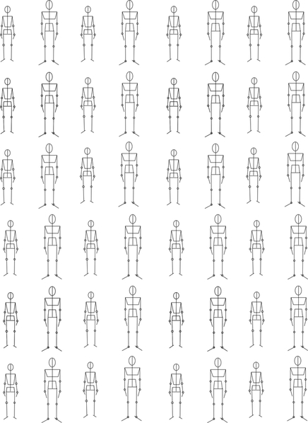
I drew up a scale sheet of figures in 1:48 upon which a decent armature can be fashioned. At least now I know the proportions are right. The woman's figure is scaled to 5'5" and the man's at 6 foot. This is not too scale so I've attached the image separately as well. The man scales to 1.5" tall so you can use that as a reference. The shoulder and pelvic pieces are supposed to be brass or some other stiff material. These were based on figure drawings found in a Google search.
Attachments
Another holiday workday while Tennis was still on. Using my armature diagram, I soldered one together (the male version) and added some clay. I noted the hinge points with a Sharpie for the elbows, knees, wrists and ankles.
I used PE brass to make the pelvic/thorax pieces, continued using the twisted wine bottle brass wire and a piece of phosphor bronze 0.021" rod for the spine/neck. I wasn't sure if the wine bottle brass was solderable since it could have been lacquered to prevent oxidation, but it soldered just fine. My first attempt at adding the clay was to add some cylindrical pieces of Sculpey slid up the arms up to the shoulder, and then a second piece up to the elbow. I then tried to add the torso pieces and completely screwed up the arm clay. And then armature broke at the spine/pelvic joint.
I redesigned the joint a little bit by flattening the phosphor bronze piece to give more surface area for the joint, and I put a little hitch in it so it would drop over the leg wire that was flat on the pelvic piece. This made it much stronger. Then I didn't do anything with the extremities, but instead worked only on the torso, leaving a small gap at the pelvis/torso joint so I could bend the spine a bit if I need to for correct positioning. I fired this part since it was very delicate and I kept deforming it when holding it. I eventually grabbed the neck rod with a hemostat and was able to work on both clay lumps without wrecking either one.
I think I may finally be on the right track. I cut brass pieces for one more male figure, and then I'll attempt a female. There are four figures in total so I'll have more practice.
I noticed something interesting when staring at the Night Hawks enlargement. The man with the hawk face is wearing a very hip, dark blue shirt. The painting was done in 1941. I had no idea that bright colored dress shirts were hip in that era. I remember when the bright dress shirt colors came out in the 70s and 80s. Who knew they were being resurrected.
Attachments
Happy Tuesday. Making figures is slowly going to drive me nuts. At this small scale, the slightest deviation (larger) when applying the clay immediately turns the figure into the Incredible Hulk. Then, there's the problem with the sculpey not sticking to itself after it cured and you're applying more clay to join the moving parts, and all the joints separate. I had to use CA to hold it all together. Then there's the problem with the head… need I go on?
I then started adding some clothing, but since the figure was already sort of bulked up when I added the clothing layer it even got bigger. He looks like he's wearing a hazmat suit. I added a lapel on the jacket and tie between the open sides. In the picture Hopper shows the man's jacket unbuttoned.
I would love Mr. Artista to teach me how to do this is 1:48. Everything I'm looking at on the Web is in much larger sizes. Much of the problem I think I'm having is simply trying to do this in O'scale. I looked through the entire Artista catalog and the only one I found that would work was the ice cream vendor since he has the same kind of hat as the counter man. Non of the seated figures were dressed correctly. I could look at them again and maybe modify the figures rather than starting from scratch. I'm going to take a break and wait until the Sculpey liquid products arrive. I've bought Sculpey Bond which specifically is used to glue together Sculpey and then bake it. I've also bought Sculpey liquid polymer clay again to give me some more options. I've at least go the armature part figured out.
Attachments
By Jove, I think you are onto something here!! Looks great!
Miles,
I am REALLY looking forward to learning how this one is going to end...
With your standards of realism, modeling those figures using these techniques is quite an undertaking. I don't mean to be a Debby-downer, but I fear that you are heading straight toward the Uncanny Valley. Even the very best of of the professionally-produced O-scale figures look slightly creepy. This is why some of the ultra-realist modelers eschew human figures completely.
My best guess is that the only way you will satisfy yourself is by making models of actual scanned people on a 3-D printer.
Knowing your work, however, I suspect you may prove me wrong. ![]()
One of my followers on this thread, Gerry, has offered some O'scale people kits to me that I can kit bash to maybe make some Night Hawks folks and I'm taking him up on the offer. Kit bashing should be easier than scratch-building these little guys.
Had very little time in the shop today, but used it wisely. Another readers suggested using the foundation stone to tie the steps into the building's theme, so I started that process today.
I laminated the stone to one of the profile pieces using "normal" Testor's tube cement and then made a corner piece that was the scale 3 feet of the step width (3/4") and adding the 5/16" protrusion of the window box giving 1-1/16" width. I then subtracted 0.040" (one styrene thickness) from this and cut the piece. I then allows the stone laminate to stick out one thickness so the edges would me perfectly in the corner. I didn't allow for this when skinning the building proper and was not happy with the material thickness visible at the edges (live and learn). I glued the inner profile piece to this end piece at the 3/4" mark, and put 1/8" square styrene corner blocks to square it up and give it some substance. I also added some of the same material cross-wise at the step end to square that end up. I added one more small piece of styrene to square up the mating to the building.
And before I go one step further I better trace the profile onto the steps that are going on the left side. There is a slight difference in the dimensions from the right side so I will custom measure that length and not depend on the length of this one. I have my Duplicutter set for the height. Speaking of height, it is set to accept a 0.040" slab on top to meet the door height. The top slab should be thicker, more like 6 scale inches. Not sure how that would work.
Attachments
Shapeways can 3D scan a person in full color then 3D print them in full color sandstone. If you run into more problems, then you could try that.
Andrew
I'm familiar with Shapeways, but I don't know how to create a good 3D drawing of these people. I've just started learning how to use Blender, which is better than SketchUp to do organic shapes, but I'm very, very low down on the learning curve and it doesn't work very well on an Apple MacBook Pro with a touch pad.
I got the word that my Sculpey liquid products are shipped so it won't be long till I can attempt to use them. Meanwhile, a faithful reader on my other forum where I post this identical thread, is attempting to shape his own people using a slightly different approach and he's sharing his results with the forum. Instead of trying to work in layers, he's loading up the armature and carving it in one go. We'll see if it's more successful. My problem with that method is that you keep deforming already-sculpted areas as you hold onto the piece. It's so small there's very little to grab onto. Layering and baking enables you to harden parts that are already correct so you won't wreck them moving along.
Got the exterior steps completed today. Glued them all together, painted concrete color and painted the stone.
After cutting and gluing the left step unit, I measured and glued up the top concrete platform. I made it a two-layer affair out of 0.040" sytrene, sanded the edges to match the layers (which were glued with tube cement) and then slightly rounded the edges as concrete often is. The top pad needs one back corner notched to wrap around the window box. I did this with a razor saw. I glued the steps starting with the top riser which also needed a notch to conform to the top platform sticking out a few scale inches from the stone foundation.
Each riser and tread had to be custom cut since there is some small deviation between the step cuts. After gluing (and reinforcing with thin CA) all the treads and risers I went back and files all of the ends flush front and back. The treads all have rounded edges and protrude a bit over the step below.
I mixed up some concrete color as before using a mixture of Tamiya Wood Deck Tan and Medium Gray. It came out a little darker than the mix that I used on the rest of the building's mortar. You can see this difference. I didn't realize that I had save that previous mix and could have used that. It wasn't until I went to save the new mix that I found the older bottle. Oh well...
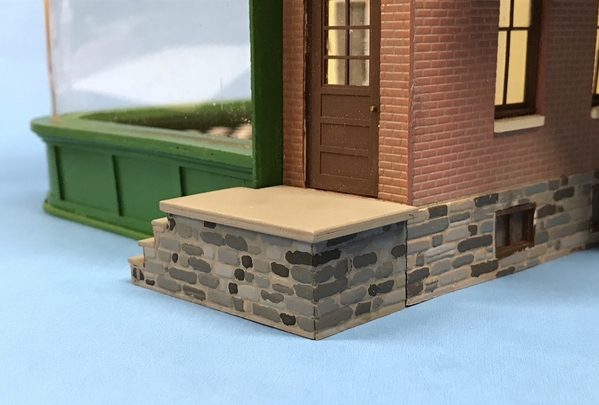
The effect of the stone and concrete is what I was looking for.
Here's the building with the steps in their place (not glued).
I was thinking about making the railing out of soldered brass, but I'm rethinking that since the slats would have to be soldered into holes drilled on an angle. I'm not looking forward to that, so I'm probably going to build them out of styrene. It will be a simple affair with a rectangular top rail and sound supports. Brass will be much stronger, but much more challenging to build.
I can't install the steps until the window assembly is in. Can't put the window in until the interior is fitted out, and I can't do the interior until the (%Y()_(5-^3@%)* little people are in place. Those people are now smack dab in the middle of the critical path. I may fill the time waiting for the people problem (hmmm… sounds like a job for HR) to be solved by building some nice small exterior LED lighting fixtures which are needed too. I also need a plumbing stack vent on the roof and can start crafting the down spouts. Still stuff to do...
Attachments
Nice job on the steps, Myles. I think making the side of the steps match the maconary was the right choice.
You really have gone above and beyond on this, and by laying it out step by step it lets us understand the craftsmanship that is going into it.
One thing I am wrestling with is that huge curved window of glass. Even today doing something like that on a 1:1 building would be a huge undertaking. I have trouble seeing why back in the day they wouldn't have gone with something easier for a building such as this.
Thank you. The curved window is not my call, it was Edward Hopper who drew that restaurant with that large curved window. It would have been MUCH easier to have flat windows. I still have to add some vertical mullions which I'm going to do with green painted tape. Hopper supposedly modeled it after a restaurant on Greenwich Ave. in NYC, where two streets joined. As you can see, the window is actually wider than what I'm doing. Whether this "real" restaurant had a curved window such as this is unknown, but one can imagine that he didn't just dream it up.
As I noted much earlier in Night Hawks part of the sage, Hopper warped the perspective making the counter a closed triangle. If your eye follows the line of the counter, you'll see that there's not going to be an opening to let the counter man out. Story goes that he drew it this way so the two main characters are seen more frontally. I am working in the real world and chose not to warp the image to conform to "American Impressionist" sensibilities. Like I've also noted, I have the painted Lally Column ready to go in when the ceiling is installed. My upper window trim is not the same as in his image, but my lower sill is pretty close. I didn't want to restrict the visual area any more since I want to show the insides and it will be viewed at distance of 4 feet. Sort of Trainman Impressionism. Night Hawks from painted in 1941.
There's no visible front door either so I'm assuming that you get into the place off stage right. I sure wish I had more stools. I only have six off them. I could get some more cut, but would want them cut from aircraft ply, not solid maple sheeting. Need some cross-grain to keep all the leg parts from breaking.
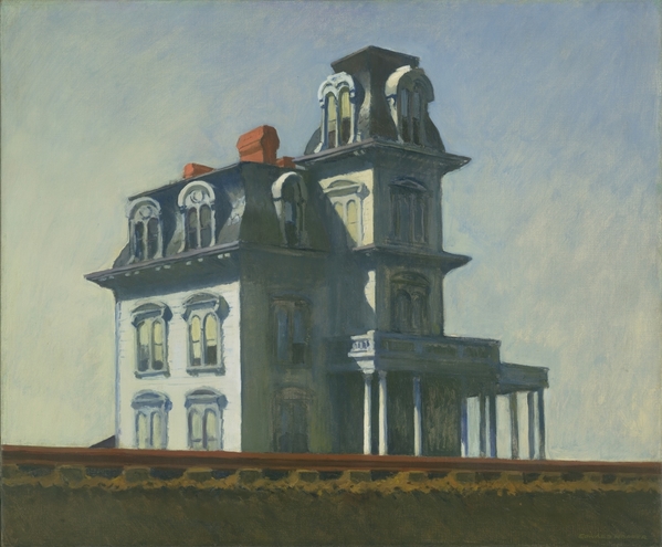
Another painting that evokes emotion is "House by the Railroad" painted in 1925, which also could be a great project for us model railroaders, especially since there are railroad tracks right in the picture. Again, it has tons of detail and a great Mansard roof. If I want something else to do when I'm bored, I could see what I could do with this beauty. Right now, I'm getting another quote on laser cutting the Bronx Victorian town house which has similar 2nd Empire details. Like that one, this one lends itself to getting all the gingerbread details 3D hi-res printed.
Attachments
I know why you are doing it that way. What I am trying to figure out is why the people in Hopper's universe did it that way. I can imagine the conversation between the architect, builder and owner.
A: I have this really cool idea. Rather than having multiple windows on the first floor we use one piece of glass that curves at the corner.
B: where am I going to get that piece of glass? How am I going to transport it to the building site? How do I keep it from cracking during installation?
O: How much is this going to cost me? How am I going to recoup that cost from the rent that crummy diner will be paying me? Do you know what my monthly payment on the loan from First Bank of Plasticville is? And what if someone puts a rock through the window.
Got it. But I don't think Hopper drew it as one piece of glass. There are mullions separating it into 4 sections: the central (small) curved piece, 2 large flat pieces and 2 more smaller pieces. I'm going to put those strips on too, but it won't be perfect since the thickness of the Plexiglass keeps the front and back mullions from actually meeting.
Yes I agree with Trainman Impressionism! That’s a great term for it!
Bill, Yes it is the engineer in us that thinks of all these things! Having an artist daughter, I understand a bit how the artist Hopper thinks differently. Believe me, they think differently! LOL
Happy Monday, and Happy New Year to all of my Jewish followers. It's 5779 (which is interpreted as the time from Creation, not from the Convenant with Abraham which is understood as the beginning of the Jewish faith). Since I am not a 6,000 year old Earth person, that date is only symbolic to me. Understanding that it takes up to 800,000 years just to create a Hawaiian island, and we're watching one being created right now, my technical understanding prevents me from accepting the literal interpretation of Creation. All I know is Judaism has been around a heck of a long time.
It was an exercise day so I got to the shop late. I am entertaining Gary Poole on Wednesday and the shop needed so serious organizing. Nothing like a visitor to light a fire under you butt to get into action. Gary saw an article about me in a Louisville publication (he has relatives here) and asked about me at the train store and we got connected. He owns a massive (100' X 30') layout in a warehouse that he purchased in Wayne County, NY.
I did do some work first. I repainted the concrete on the steps to lighten it up a bit. I placed the steps on the sidewalk it was to sit on the layout and the contrast was too sharp. I just brushed painted it since it had a nice base coat and the colors were similar. I then measured and laid out the design for the simple railing that I'm going to scratch-build out of styrene. The top rail will be 0.040" X .100", bottom rail will be 0.030" X 0.080", vertical supports 0.060" X 0.060" and the bars 0.040" round rod (all Evergreen).
I use an old Bar Mills wooden model box to hold all my Evergreen strip stock, and it was an utter mess. A long time ago, I had sorted it all by type, but it was getting more and more random. I was spending a lot of time shuffling through this box looking for a specific size. THOSE DAYS ARE OVER (at least for now). I stopped working on the steps and decided to organize this mess. I cut up some cardboard 3 X 3" pieces and called out the widths on them. On the Evergreen rack at the hobby shop, they're sorted by thickness. I'm more concerned about width as my first consideration so that's how I'm indexing it. Then I stacked the stock from the thinnest to thickest. It took about 1/2 hour to do this, but it will be worth it.
That got me started. I saw, in either a Facebook page or in one of Fine Scale Modelers' Tips pages, that a fellow made a simple set of tool holders by just taking some scrap wood and drilling some holes in it. I can do that! So I first made one for the pliers and cutters. The largest hole I can drill without a spade bit is 1/2". For the mechanics pliers I had to use a smaller (29/64ths) drill so they wouldn't flop over. This was a chunk of the first iteration of my layout's control panel and that flange that was still glued on worked to my advantage so it would tip forward. That's German dimensional lumber and ply on that piece. Also shown is the holder for the needle files using a slightly-bigger-than-1/8" drill.
I then quickly made one for the tweezers. This is not all the tweezers, but it's the ones that get used the most. For this I drilled clear through and then glued a piece of ply to the back to keep them from falling through. Have to be careful reaching for them to keep myself from being impaled on them.
I then did more general cleanup with some more to go. When Gary gets here on Wednesday, at least I won't embarrass myself.
Lastly, Gerry's little people came today and I believe they will solve the little people problem. They are in multiple pieces and the arms are positionable. The man has a Fedora hat and could fill in for Hopper and there are some women too. And they're seated figures as well as standing. Even if they're not perfect, (scale seems slightly undersize) they are a great start! I'd rather have them a little slight than oversized. Thank you Gerry!
Tomorrow, I'll finish the cleanup and then get to work fabricating the railing and the little people. My wife commented about my new found organization, "Now all you have to do is remember to put the tools back in their new holders…" After 50+ years of marriage, she knows me well… way too well.
Attachments
Myles,
i follow every one of your posts with great admiration. When you mentioned you studied industrial design awhile back it went a long way in explaining where your skills may have been so finely honed. In college i had two fraternity brothers who were in the college of architecture and one dorm mate who was an industrial design major, and i was always amazed at the skill and creativity their projects demonstrated. Keep your posts coming.
Happy New Year
It makes me very happy that folks like you (and many others) appreciate this effort. It's hard to believe that this thread is running now for 6 years with many of you are still following. I'm also glad that I am healthy enough in mind and body to keep it all going.
I was an industrial design major for much too short of a time. It's a long story and someday, if I'm feeling annoyingly nostalgic, I will regale you with it. Meanwhile, most of my intensity around design is that I am a frustrated design engineer. Even during my extensive training career, whenever I had a chance to do something interesting involving design I would take it. As a retiree, I'm actually living out a life-long desire. As a kid with a 13 X 4 foot O-27 layout I dreamt about having a big railroad and only now 60 years later do I get the opportunity to realize it.
Today I built one of the two outside step railings that I need. It took all afternoon to build one. I started by cutting the pieces to length, and laying out the spindle spacing with a machinist dividers. I then tack glued the top and bottom rails together by just a drop of solvent cement at the ends of the bottom rail to hold it in place so I could drill both sets of holes in exactly the same places. The bottom rail sits between the end posts and is therefore shorter than the top rail. I had to pay attention to this setback when I glued them together.
I drilled the ends of the posts and CA'd a short piece of 0.021" brass so It will have some mounting strength on both top and bottom. One of the holes was out of line, but it's not noticeable in the final assembly.
I assembled the spindles into the bottom rail first flush with the bottom and then inserted into the top rail letting the excess protrude out the top for later trimming. The top rail, as I noted, has holes corresponding to the brass pins in the end posts and these were glued with solvent and then CA cement. I then glued the bottom rail in place. I quickly found that I positioned the post too close to the end and had to glue a styrene spacer to fill the gap.
After the glue dried I filed all the protruding spindles and rods so it was ready for painting. The right angle rail was next and only had one end post since it shares the corner one. That led to a challenge since I was measuring from a 45 degree angle cut since I mitered the top rails at the corner. As I'm writing this, I think that was overkill and greatly increased complexity of the build since the hole for the corner posts brass pin came way to close to the miter cut. For the left side's railing I'm going to make the corner a butt joint. I located and drill the brass pin holes into the "cement" pad and temporarily fit the rail onto the step.
I custom measured the side rail for this particular step since the left and right steps are slightly different widths. I then had to build the angle rail. I first tried to do this on my drawing. Everything was going well until I tried to assemble the parts and found that my holes were not drilled at the correct angle (too close to vertical) and the assembled rail just didn't fit and I couldn't bend it enough to make it work. So I went to plan B which was to build it in place.
I drilled and glued in the corner post at the bottom step. I probably could have had this post at the pavement level, but I realized that it would just waving around in the breeze until the building was planted, so I terminated the rail at the bottom step so the entire step could be a complete assembly. I then measured, cut and sanding the 45° angle on the top end, and noted where the brass pin hole would be on the bottom end. I drilled that hole and glued the top rail in place.
I measured the distance for the bottom rail in situ and worked the cutting/sanding in stages to creep up to the final fit. Holding the lower rail on top of the upper rail, I sighted straight down to find the center of the steps and made a mark where that point would be on the bottom rail. I drilled the 45° holes with the starter drill (a carbide 0.021" drill) and then marked this position with the drill using the bottom rail as a template on the top rail. I then drilled the starter holes in the top rail. I opened up both sets of holes with the 0.040" again at 45°. It was a tricky drilling job since the top rail was not that securely held in place.
Again, I put the pins through the top rail and bottom with the pins roughly flush with bottom rail's underside. After positioning the bottom rail I added solvent cement to all the joints and let it dry.
At this point I was at the end of the session, but I was a bit concerned that the steps might extend to far into the existing sidewalk next to the building, so I stuck the building on the layout to ease my concerns.
As you can see, there's plenty of sidewalk next to the steps so that worry was without cause. It looks nice in that corner and the curve of the window follows the curve of the street corner nicely. You can also see the utter destruction of the streets due to the moisture that was present from the dishwasher leak. Even though there was no direct flooding—the plastic sheeting prevented that—it still did some damage. I'm going to have to remove all the structures (luckily I didn't glue any of them down) remove the Strathmore upper layer as carefully as I can so I use them as patterns to cut new laminates, and then cut and glue down the new surface. In this case, It's going to be Masonite since my curbs are way too high and a thicker top layer will work. I hate doing work over!! Some things on this layout are already five years old and will start requiring maintenance just from being there.
Attachments
Nice job on the railings, Myles. I admire your patience and attention to detail and realism. Your pictures didn't come out in the writeup. They did come out at the end under "Attachments" though. So I was able to follow along.
Yes Myles, if we’re to print this out and put it in book form, I may not be able to lift it!! Excellent information and dialogue!
The little stoops and steps are looking great, as does the nearing completion building looks in its planned corner location!
You guys are too kind! I fixed the post to include the missing images.
Well… it's Monday and I'm back from my Detroit trip. It was definitely a trip fraught with mixed emotions. On the unhappy side I was visiting a very old and dear friend (the drummer in my band) who suffered a cerebral hemorrhage and was suffering from paralysis on his left side. He's in a re-had facility trying to recover. On the happier side I visited with another very old friend (55 years) who had recovered from some serious complications from a knee replacement and his daughter made him a 75th birthday party which I was able to attend. I know many of his family members so it was a reunion of sorts for me. My other very old friend and bass player in the band was planning on coming up from New Mexico to attend his high school 55th reunion on the same weekend and we were able to have time together and he saw the drummer too. So we covered a lot of bases. It's a 5.5 hour drive from Louisville to Northern Detroit metro area.
I brought back with me my friend's MTH PS-1 Premiere Cab-forward which got some maltreatment from some of his younger grandkids and needs some desperate work. The side rods were bent, the valve gear is also, and one of the four return-crank die casting fractured. He had left it at a hobby shop in Troy, MI for many months, but they were unable to fix it since they said the parts were no longer available. He gave it to me to see if I could do anything with it. Roundhouse Trains here in Da Ville may have more skill in repairing it. I might try myself also. The other problem is the hobby shop seems to have misplaced the tender. Without it, that engine doesn't do anything. If they can't find it, I don't know what the remedy is.
I got back to "work" today. First of all Costco had LED shop lights on sale again so I bought one more. This one replaces the florescent one over the ravine area. I also illuminates the chop saw on that wall. I also attempted to peel up the strathmore paper layer on the streets to see how easy this will be (as a test) and I was able to pull it up in one piece. This way, I'll be able to use the entire strathmore layer as a pattern for any new streets material I'm going to use. Illustration board might work, or I can us thin Masonite.
I could use one more light directly over the ravine area and the back of the layout in that area since there is a dark area there and the new one doesn't reach in there.
I completed the railing assembly for the other set of front steps. This one went considerably faster than the first, but almost had a catastrophe. I had it all finished and wanted to put some medium CA at the base of the posts to lock them into the holes in the pad, but mistakenly picked up the thin CA. To make matters worse, the extension nozzle I have on this bottle has a larger bore than one would like with thin CA. So when I tipped the bottle a giant squirt came out and soaked part of the steps, my fingers and made a royal mess. I scraped the excess off of the pad and attempted to put the railing into the holes since I had removed some of the posts to scrape the CA. When attempting to put the post pin back into the hole (which had now had cured CA in it) I put too much pressure on the post which fractured, the bottom rail was destroyed, but the spindles remained attached to the upper rail. I was able to build a new post and new bottom rail without taking apart the rest of the railing and got it all back together.
So I'll have to touch up the concrete color and mask and paint the railings the BN Green like the rest of the trim. And then it's time to build the little people.
Attachments
That is great you got to see many old friends! It is sad one friend is so bad off from such a serious condition.
Wow, it’s a shame that shop misplaced your friend’s tender. Hopefully that repair project will come together.
Thanks for the kind words, Mark! He was beginning to get some motor control of his left side and then today another setback. He suffered some pulmonary embolisms. He's back in the hospital and there's an additional challenge since using blood thinners is not recommended since he had a brain bleed. I'm assuming the clots are the result of his left leg being out of commission for over two weeks. It's definitely a bummer. I'm very glad I was able to see him.
Today, the little people populating Night Hawks problem was solve with Gerry's gift to me; those O'scale people kits. I was able to cobble together (a la Dr. Frankenstein) figures in reasonable postures to take their place in the vignette. The first person (Hopper himself) was already in a sitting position so I had to add arms that would clear the bar top and slightly modify the hat he was already wearing. It's not an exact copy of the hat, but it will give the right impression. I removed the left hand and turned it 90 degrees so it was more in line with the picture. In the picture, that arm was flat on the counter top, I tried heating an arm and bending it downward, but that only resulted in a ruined arm, so I left it alone.
The other guy (I'm calling him "the other guy") was a different situation since, although I had other seated male figures, I didn't have any more that were wearing a suit. There was one figure with his arms behind his back in a standing position that could work if I could give him new sitting legs and remove the arms to put on others in the kit that were separate. I cut his lower body off and removed the legs from one of the other sitting figures and glued them together. I used a carbide router to remove the arms and put on another set of separate arms, again making sure that they would clear the counter.
Here's the finished "other guy" seated at the bar. His hat was on one of the female figures. I narrowed the top and thinned the brim a bit, cut the top of his head off and glued the hat on.
The lady presented less of a challenge since she's not wearing a hat. The hair won't be as long, but again, this will be viewed from almost 5 feet away and she's sitting behind the man, so as long as it's a nice shade of red hair, it should be believable.
The last thing was the counterman. The picture shows him leaning over, but I didn't have any people in this position. The very formal man was standing straight up. I made a hat out of Super Sculpey. I've found that for these small Sculpey jobs, I can harden them quickly by just using the heat gun for a couple of minutes.
So here's the whole entourage in their positions. I need to get another batch of stools cut since I seem only have five workable ones. I need about a dozen. They all need to dry solidly so I can go back and add some strategic filler in some various ejector pin holes and clean up the joinery a bit. Then I'll paint them. If I'm going to get more stools, I better get cracking since this will again be a bottleneck on the critical path. I'm also going to put a brass foot rail at the bottom of the counter base.
Attachments
I went back and forth from the Hopper paining and your last photograph. Yes, they are quite presentable as stand-ins for Hopper and his group! At 5 feet away, they will look perfect!!!!
Thanks Mark...
And the illusion will be confirmed since I will attempt to match the coloration in his painting. With her red dress, red hair and very red lipstick she'll do well.


