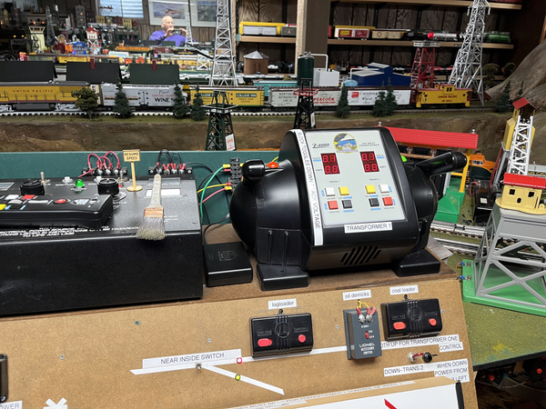
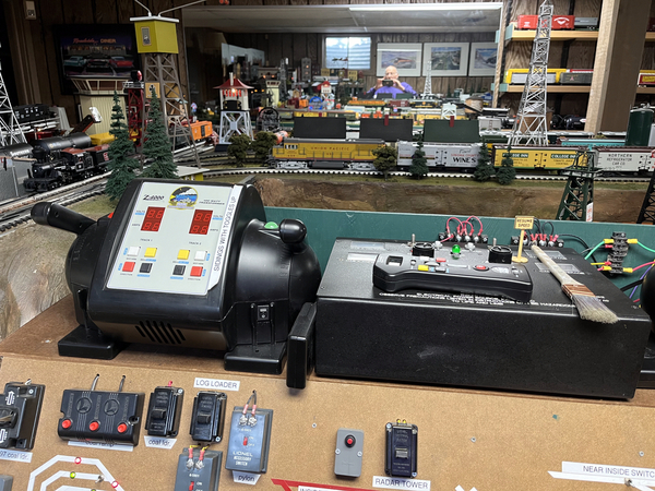
I’m having a hard time, deciding how to control my switches, turntable and blocks


looking for advise.

I’m at the point of my layout where I need to make this decision to continue.

I’ve always been enthusiastic about electronic systems that are constantly being updated.

But I know it’s good to go with the kiss method (Keep It Simple Stupid).

from what I understand, there’s no way to do both control board and digital control

Original Post

Replies sorted oldest to newest

Why not use digital to control your trains using DCS or TMCC and have a control panel with a diagram of your layout and toggle switches to control blocks, and switches? I used Tortoise switch machines with bicolor leds used to indicate in which direction switches are thrown. Also, I have a number of Lionel , MTH and K-Line accessories that have their control switches on the panel. To do all of this on an ipad or your phone would be too much for me to handle. Reach me at milt@paiger.org to discuss further if you wish.


from what I understand, there’s no way to do both control board and digital control

False, you can 100% do both digital control (example LCS or just regular command control address each switch) AND run a physical control panel at the same time.

Many of the LCS or command control modules (example SC-2, or the TMCC version of the ASC box) use relays and thus are compatible with physical switch control methods because they do not interfere- true even for other switch motors and brands- not just Fastrack or Lionel Tubular switches.

You can wire it one way and add another control method later in parallel.

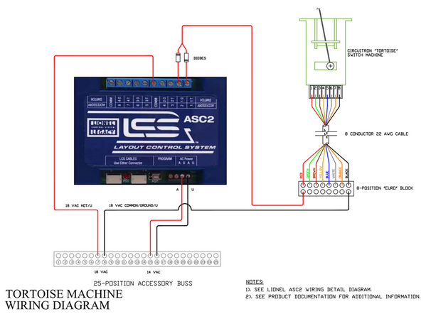
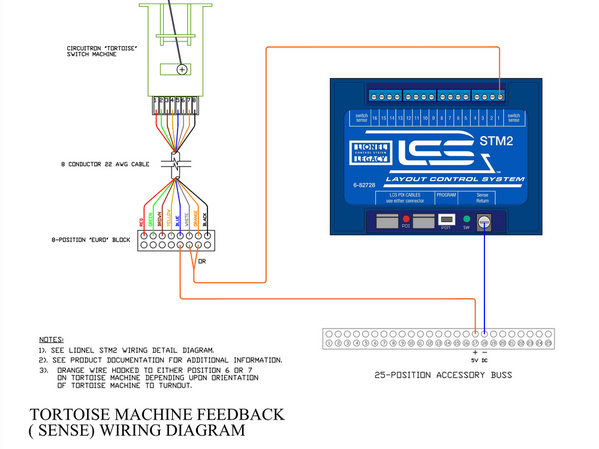
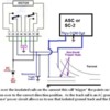
Not so sure a duplicate manual control is easy to do with Tortoise machines. In the connection diagram from my layout below, either terminal one or two of the ASC 2 is always powered to provide the power to the stall motor. The two steering diodes rectify the 18VAC input to set the straight or divergent position.

Just the ASC 2 is needed for controlling the turnouts with a Cab 2. If an iPad is used then an STM 2 is added so the turnout position is always shown correctly on the iPad(s).


IMG_1681IMG_1682

Attachments

Images (2)
  • IMG_1681
  • IMG_1682

Vernon,

i’m using tortoise switches so I would love to learn more about how to use the LCS modules and do a control panel at the same time. Is there any document documentation on how to wire that?

https://ogrforum.ogaugerr.com/...c/156561155754823710

Another topic using the AIU but wiring to just about any of the Lionel devices would be similar (ASC, SC-2) https://ogrforum.ogaugerr.com/...mote-tortoise-wiring

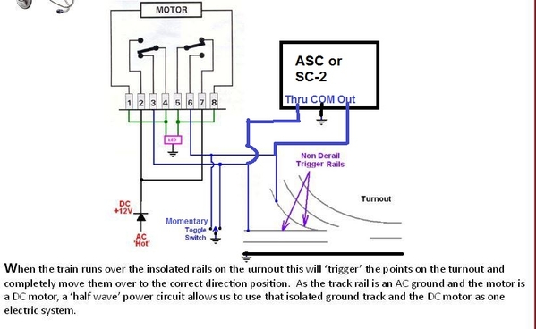
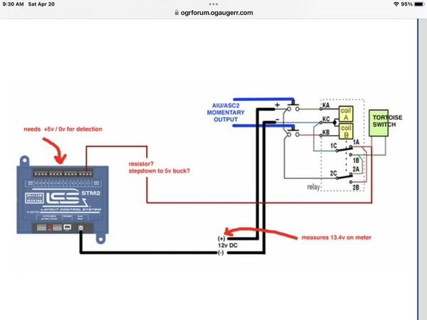
My own edited take on the drawing from one of those topics

Tortoise switch wiring

The momentary (important aspect, you do not want a latching toggle switch- middle off) toggle is the manual control, and the ASC or SC-2 can also trigger and change switch position as well as the anti-derailing sensing rails.

So right there is technically 3 ways control method, all in parallel.

Attachments

Images (1)
  • Tortoise switch wiring

One note, the ASC or SC-2 or AIU, they support either momentary or latching control modes of the outputs.

If you use momentary- you have to press the control button long enough for the motor to fully switch and hit the end limit. This is a training or user habit you must make sure you fully switch by holding the control button or toggle until fully switched.

If you chose toggle or latching mode- then you have the problem of that fighting and preventing a parallel input like anti-derailing sensing or manual momentary button or toggle switch control panel. Again, latching mode makes sure the switch fully moves all the way each time- but then because it's latched and "active", an opposite parallel input  won't work and is defeated by the latching nature. For all inputs (example control panel, command, and anti-derailing) to work, they all must be momentary.

Last edited by Vernon Barry
@AmFlyer posted:

Not so sure a duplicate manual control is easy to do with Tortoise machines. In the connection diagram from my layout below, either terminal one or two of the ASC 2 is always powered to provide the power to the stall motor. The two steering diodes rectify the 18VAC input to set the straight or divergent position.

Just the ASC 2 is needed for controlling the turnouts with a Cab 2. If an iPad is used then an STM 2 is added so the turnout position is always shown correctly on the iPad(s).


IMG_1681IMG_1682

I am wiring my ASC2 and my Tortoise.

In the Tortoise instructions show no more than 12V AC or DC

In your diagram it shows 18V

https://ogrforum.ogaugerr.com/...c/156561155754823710

Another topic using the AIU but wiring to just about any of the Lionel devices would be similar (ASC, SC-2) https://ogrforum.ogaugerr.com/...mote-tortoise-wiring

My own edited take on the drawing from one of those topics

Tortoise switch wiring

The momentary (important aspect, you do not want a latching toggle switch- middle off) toggle is the manual control, and the ASC or SC-2 can also trigger and change switch position as well as the anti-derailing sensing rails.

So right there is technically 3 ways control method, all in parallel.

Vernon,

I have a Barrett Hill DC switch (DB8 board and momentary manual switches) can you power the Tortoise switches through your ASC2 with DC power?

Vernon,

I have a Barrett Hill DC switch (DB8 board and momentary manual switches) can you power the Tortoise switches through your ASC2 with DC power?

The ASC2 output is just relay contacts- so sure, AC, DC, whatever on the output side.

The whole point of a relay is to isolate the input from the output and allow different voltages and currents from the control circuit VS the loaded circuit. That said, the ASC2 itself, beyond the PDI cable, needs an AC power source to activate the internal relay coils.

As with any device you are considering buying, I read the manual FIRST and the specifications https://www.lionelsupport.com/...250%20LCS%20ACS2.pdf

Attachments

Images (2)
  • mceclip0
  • mceclip1

Vernon,

I have a Barrett Hill DC switch (DB8 board and momentary manual switches) can you power the Tortoise switches through your ASC2 with DC power?

I was trying to research this system and maybe it's just the marketing, but that base- DB8, seems to mention toggle style inputs. You mentioned Momentary manual manual switches.

The most important thing is how the system handles a conflict. Example, if the output of the DB8 is toggled or latched and you parallel the ASC2 relays capable of 20A, the output of the DB8 might fail in conflict (DB8 set one way, the ASC2 commanded another). The hope is that we use momentary on both control methods, and neither latches a state, making the system free for other input (example anti-derailing sensing).

To me, some more robust relay outputs might be better insurance on the Berrett Hill control system, maybe some PTCs or fuses and low current limit on the source just for good measure? This is why I like the common wiring and basically using return path method of control. Any return currents are limited by the motor and diodes before ever hitting any relay, and all they do is connect to common.

https://ogrforum.ogaugerr.com/...c/156561155754823710

Another topic using the AIU but wiring to just about any of the Lionel devices would be similar (ASC, SC-2) https://ogrforum.ogaugerr.com/...mote-tortoise-wiring

My own edited take on the drawing from one of those topics

Tortoise switch wiring

The momentary (important aspect, you do not want a latching toggle switch- middle off) toggle is the manual control, and the ASC or SC-2 can also trigger and change switch position as well as the anti-derailing sensing rails.

So right there is technically 3 ways control method, all in parallel.

Tried your set up and no results

On the power (AC/DC +) for 2&7 do you have to use diodes? If not what voltage?

Now that I am back home I was able to verify how the ASC 2 works in Momentary mode. I have a lot of ASC 2's set to Momentary. The ASC 2's set to Momentary on my layout actuate DZ-2500's, uncouplers and action car tracks.

Using a Cab 2 handheld, enter ACC, then the TMCC address, then push the AUX 1 button. As long as Aux 1 is held down a continuous signal will be sent, causing the relay contact in the ASC 2 to stay closed until the AUX 1 button is released. If an iPad with the LCS App is used, the functioning is different. Touching the icon on the iPad screen causes no action, releasing the icon, that is removing your finger or Apple Pencil from the icon, causes a fixed .25 second closure of the ASC 2 output contacts. That is not long enough to throw a Tortoise actuated turnout. It would require multiple successive touches when using an iPad.

Vernon Barry posted a link at the top of this thread to a design that ScottV uses successfully. ScottV's design has all inputs controlling a twin coil relay. The contacts of that relay are used to power the Tortoise. To me that looks like the best approach to integrating multiple controls of a Tortoise.

Thank you for responding to my post.

I was trying to respond to Vernon on that Diagram he posted I guess that is Scott not sure.

I had a question on the AC hot in the DC 12 V. I know the tortoise switch will not allow anything more than 12 V and all I have available is 18/14 and 10.

not sure if I need a voltage regulator I have 20 of these switch machines and just try to get them started to my first big layout.

I was trying to do a test track. I don’t have my Manuel switches yet so I was trying to wire it without the manual switch and and only to the ASC2 for testing.

Attachments

Images (1)
  • mceclip0

Below is the diagram Vernon Barry linked in his earlier post. Note ScottV is using a twin coil relay to convert momentary inputs to latched inputs that the Tortoise requires. For multiple momentary inputs just add them in parallel with the two blue inputs. The Tortoise will be positioned to the most recent input command.

IMG_3316

Attachments

Images (1)
  • IMG_3316

Use 10V and call it good. These are not electronic switches- a DC can motor and 2 switches.

I had a question on the AC hot in the DC 12 V. I know the tortoise switch will not allow anything more than 12 V- FALSE!!!! There are no electronics or voltage limit. It's a suggested voltage for the motor.
and all I have available is 18/14 and 10.

not sure if I need a voltage regulator I have 20 of these switch machines and just try to get them started to my first big layout.

I was trying to do a test track. I don’t have my Manuel switches yet so I was trying to wire it without the manual switch and and only to the ASC2 for testing.

Again, use 10V first, if not enough after the diode try 14V (which sounds like the Z4000 accessory outputs). There's losses and half wave rectification going on with no filter this is just way more thought than this deserves.

Again, a tortoise is a can motor and internally connected 2 switches- It's not that critical.

Lets try this explanation. This circuit does not use steering diodes like mine does that I posted above. This circuit uses only one diode, as shown on the diagram in the lower left. All it does is half wave rectify the AC power to run the motor. The motor direction is set by which motor terminal has the plus and which has the minus DC voltage connection. That polarity is determined by the two Tortoise internal contact sets. These are pins 2,3,4 and 5,6,7. All the control inputs do is connect the AC input power (from the center rail) after the diode to the outside rail to momentarily complete the circuit. This powers the motor for as long as the pushbutton is held down.

The circuit as drawn shows earth grounds in three locations. That is incorrect since this is a transformer secondary which is not grounded. Those three symbols should be replaced with a "return to transformer common" designation. It would not be good if someone actually connected them to the green wire on the primary side.

@AmFlyer posted:

Lets try this explanation. This circuit does not use steering diodes like mine does that I posted above. This circuit uses only one diode, as shown on the diagram in the lower left. All it does is half wave rectify the AC power to run the motor. The motor direction is set by which motor terminal has the plus and which has the minus DC voltage connection. That polarity is determined by the two Tortoise internal contact sets. These are pins 2,3,4 and 5,6,7. All the control inputs do is connect the AC input power (from the center rail) after the diode to the outside rail to momentarily complete the circuit. This powers the motor for as long as the pushbutton is held down.

The circuit as drawn shows earth grounds in three locations. That is incorrect since this is a transformer secondary which is not grounded. Those three symbols should be replaced with a "return to transformer common" designation. It would not be good if someone actually connected them to the green wire on the primary side.

I think I understand it more now.

I am using the Z 4000 but my question is I’m using the accessory power.

will that conflict anything if I tie to the track common for the derailer or should I be using the power from the positive middle track to power the switches?

Tortoise switch wiring

Here is how I wired it.

AC Hot: Z4000 14V) DC + 12V (with a diode is was about 7VDC) Connected to 2&7 / Common back to Z4000 Common

ASC2: 1T-#3/ 1O-#6 (I did not connect to track for de-rail trigger at this time) (No toggle witch connected)

Jumper wire to (1&4) and (5&8) (Did not connect a LED at this time and no common for LED)

I tried the diodes both was and they fried both times with no movement.

Trying to find out where I went wrong.

For now I went back to the below diagram and works fine. I just will not be able to have both Control Panel and ASC2 Command.

Attachments

Images (1)
  • mceclip0

I have a couple of thoughts on this. First one is the design ScottV has is better because it uses a twin coil relay to power the Tortoise as a stall motor. I believe the problem you have is caused by the design of the internal Tortoise contacts. The motor needs to run for a second to move the connection to the other set of contacts inside the Tortoise. The relay approach flips the connection almost instantaneously.

I have a two rail layout so there is no anti derail connection. I have never needed one because the engine just stops if it approaches an open turnout because the frog power is not correctly set. The best way for local control is to use multiple iPads, or just walk around with the Cab 2.

I agree I think I have the derailer is not a big deal for me keeps me more interactive than the layout. The only thing I wanted to accomplish was having the capability of using the ACS system and also control panel manual switches.

I went to a train show today in my town and just ask a lot of the veterans what they do and it seems they still stick with the old Control Panel switchboard

So maybe i’m over complicating it.

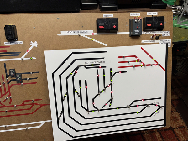
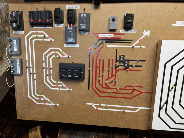
As I said on a previous post using double pole double throw toggle switches to control the Tortoise switch machines and the bicolor LED's as shown on the instruction sheet that comes with the Tortoises give you a visual idea as to how the switches are positioned. A control panel can be simple or highly decorated, but a simple diagram of your layout using auto pin striping tape interrupted by 1/4 inch holes for the toggles and the led's as well as simple toggles to control power to your sidings works flawlessly. No fancy electronics. If you want a walk around throttle us the Lionel or MTH hand held units. The control panel also allows for placement  of accessory control switches. Here are some pics from one of my 37 year old panels. Nothing fancy, just functional work stations. I try to adhere to the KISS principle. (Keep it simple, Stupid)3498B794-0E06-4F5B-A909-E5D490DCB939318CBF0D-023A-4324-9E2F-D710C12E6CA638A09992-00E0-4149-B4A2-7EC40CEB1AA20D921EBF-C621-4EB4-84A9-088DD090A2C6

Attachments

Images (4)
  • 3498B794-0E06-4F5B-A909-E5D490DCB939
  • 318CBF0D-023A-4324-9E2F-D710C12E6CA6
  • 38A09992-00E0-4149-B4A2-7EC40CEB1AA2
  • 0D921EBF-C621-4EB4-84A9-088DD090A2C6
@triplex posted:

As I said on a previous post using double pole double throw toggle switches to control the Tortoise switch machines and the bicolor LED's as shown on the instruction sheet that comes with the Tortoises give you a visual idea as to how the switches are positioned. A control panel can be simple or highly decorated, but a simple diagram of your layout using auto pin striping tape interrupted by 1/4 inch holes for the toggles and the led's as well as simple toggles to control power to your sidings works flawlessly. No fancy electronics. If you want a walk around throttle us the Lionel or MTH hand held units. The control panel also allows for placement  of accessory control switches. Here are some pics from one of my 37 year old panels. Nothing fancy, just functional work stations. I try to adhere to the KISS principle. (Keep it simple, Stupid)3498B794-0E06-4F5B-A909-E5D490DCB939318CBF0D-023A-4324-9E2F-D710C12E6CA638A09992-00E0-4149-B4A2-7EC40CEB1AA20D921EBF-C621-4EB4-84A9-088DD090A2C6

I agree that’s what I’m gonna do. I appreciate it

looks good.

Add Reply

Post

OGR Publishing, Inc., 1310 Eastside Centre Ct, Suite 6, Mountain Home, AR 72653
800-980-OGRR (6477)
www.ogaugerr.com

×
×
×
×
Link copied to your clipboard.
×
×