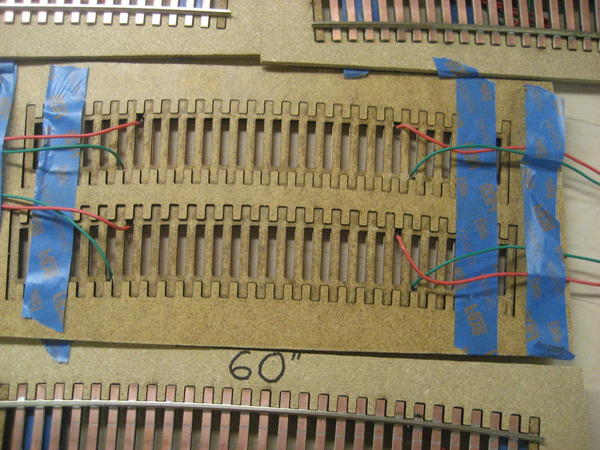
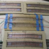
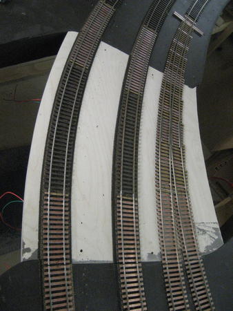
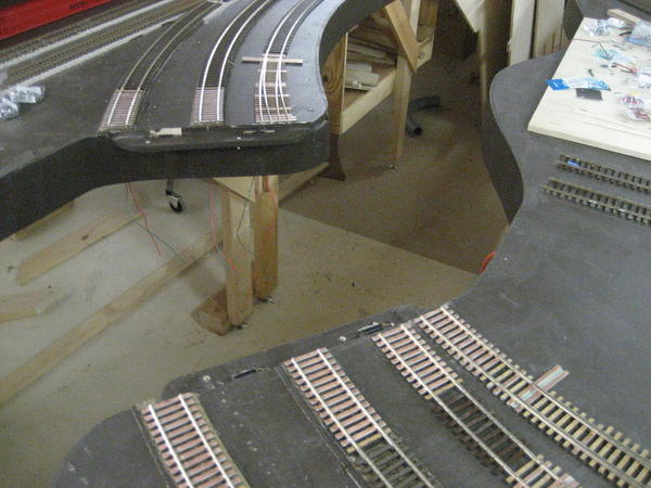
Working on a layout with several curved lift out sections.  I always use stiff  "Snap Track" straight sections at module and lift outs to assure track alignment. 


Not having any large radius rigid curved track on the open market I turned to Brad Strong 801.884.6354  a custom trackwork builder.  He supplied a variety of sections with pre attached drops on each end so as to have feeders for when the track is installed and then I will  slit the track piece as needed for seperation.


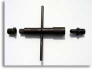
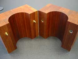
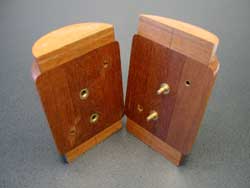
Photos should finish the explanation:

July 2013 015

July 2013 017

July 2013 018

Attachments

Images (3)
  • July 2013 015
  • July 2013 017
  • July 2013 018
Original Post

Replies sorted oldest to newest

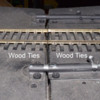
I have a curved lift up section with a 54 in radius. I used Atlas Roco flex track with six wood ties on each side of the joints. I spiked the rail to the wood ties. See the attached photo. In addition to he deadbolts I have a 1/4 in carriage bolt with a wing nut through the bench work at the joint. I tighten the wing nut to hold the lift up in place after I adjust the alignment at the joint. The lift up has been in service for about five years with no problems due to changes of seasons.


Larry Kline

Pittsburgh, PA


Curved lift up joint


Attachments

Images (1)
  • Curved lift up joint

I was recently looking at a lift-out section on a friend's HO railroad. I noticed that he had originally used vertical alignment pins but now had drywall screws. He says the pins didn't always align accurately enough so now he aligns by eye and gently turns down the screws to hold position. Of course alignment shouldn't be as critical with O-gauge, but having multiple curved tracks and a switch to boot complicates things. Temperature and humidity changes can affect the wood framework over time.

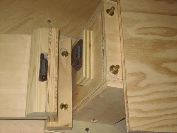
Austin Bill, at times I use magnets to hold lift outs in place.   Sometimes just one magnet and it's contact plate.  Other times I use two magnets face to face as shown for a stronger connection.


Shown below is the bridge abutment on the right and the lift out bridge on the left in an inverted position.


Three bridges 006

Attachments

Images (1)
  • Three bridges 006
Last edited by Tom Tee

Bill, How about a pair of cabinet magnets facing up on each side of the bridge contacting a properly sized metal over hang similar to the straps shown plus a linear bolt action pin mounted on the bottom of the drop span to provide an absolute safe guard against an accidential bumped drop.


The only action needed to drop the bridge would be to flip the bolt action and withdraw the pin.

Tom, that looks great!  I'm going to need a lift out section and yours is one of the most impressive and thought provoking of any I've seen. You spent some quality time designing that arrangement using pins and magnets. Looks bullet proof. Just printed off this thread as I don't want to lose your photos and instructions.


Thanks, 


Butch 

Butch, Thank you for the kind words.  A little background on the dowel pins:

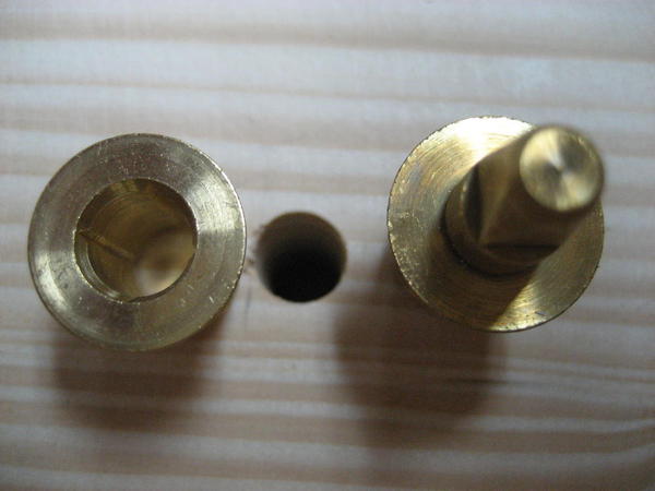
Freeman Square-Head Brass Dowels
Freeman Square Head Brass Dowels are used for hard and soft wood pattern equipment, plasters and plastics.
The square dowel head provides four wide flat areas that fit perfectly into the Dowel Inserting Wrench assuring accuracy and control when installing both the pin and the bushing. The large contact surfaces of the male dowel will withstand the strain of removing without stripping.

The difficulties of squaring the wrench to the dowel and to the work, when inserting, have been eliminated because the Dowel Wrench covers the entire pin of the male dowel down to the flange of the dowel.


Square Head Style
True-Line Style

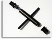
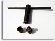
Installation Wrench

Slotted Wrench
Milled Wrench
One side perfectly fits the bushing while the other side perfectly fits the dowel pin

I spot face the hole location in the wooden surface to clear the pin's flange.
Last edited by Tom Tee

All,  thanks for the great ideas.  I chose a swing down bridge because the piano hinge end is really stable and because a swing up bridge won't work for my application. 


Never really considered a lift out bridge.  But, with all of the techniques above I can see many advantages to a lift out bridge which also fits my application.  

Lift outs have been my favorite.  Either mechanical or manual.


I built benchwork for a good sized display RR which has two lift bridges which use the square dowels.  The owner of the benchwork did an expert adaptation of pocket door trolleys to develop a neat pully lift system for one of the bridges.


This RR is now for sale.


If you want some lift out ideas I have an assortmemnt of lift out photos I can send directly to you to keep this thread uncluttered. tt


click on the You Tube icon for an overall viewing:


http://youtu.be/nG5qv-mUv40


Attachments

Videos (1)
Lift out on trolley
Last edited by Tom Tee

Sorry for the delay Tom, but here is video of our lift bridge w/relays for safety and locking brass dowels for alignment and powerwerx/Anderson power poles harness. A lot going on in one little section but works great and looks great w/silk city bridge laser cut job. Thanks for watching and please pass it on this entire benchwork/setup is for sale and on the for sale section.

http://youtu.be/MPi7q2thrkQ

I agree. I've seen Tom's work in the past and he is a master craftsman when it comes to benchwork so I was not surprised to see how nicely your layout is constructed. I really like your basement too. What a really cool train room. Now that's what I call a man cave. I'm happy to hear that you're not leaving the hobby. I hope you can find a good home for the layout. My favorite part of the video is going through the bridge. That looked really cool.

There is a range of product which would serve well.  Size #3, #4 or #5.   However under the guidance of a shop who uses these in another field I selected #4 size.


I use the #4 size for module set up purposes also. I used #4 in  The Train America Studio  portable layout seen at York awhile ago.  These alignment dowels can make bolts. screws, wingnuts obsolete or at least optional.  Simply draw close together and clamp the frame member.  I like to use welders vise grips, see below.


I did make my own female seat installation tool for doing ledge installations by machining a 1/4" drive socket extension to fit the inside corners of the round hole. If you have not seen the product that statement would sound contradictive.


Do not try this installation with out using the installation  tool.  You will regret it!


You will also need to spot face the benchwork to receive the dowel flange.


162020Square-Head Brass Dowel - Size 4 - Complete Set of 50


/Bx163555Installation Wrench (Freeman & Master) - Size 4


163595Counterbore - Size 4


Proper installation of dowels and bushings for precise alignment of patterns and core box halves is one of the more challenging processes to explain. This guide will show you in detail the proper procedure, which will apply to all of the dowels that Freeman supplies.


The two diagrams on the right show brass dowels used to align two halves of a core box (top) and two halves of a pattern (bottom). Installation of brass dowels (used in wood only) are relatively simple, requiring only a drill to create a hole of the proper size and depth and a special wrench to insert (and remove) the dowels and bushings.

Installation of steel dowels (used in aluminum, cast iron and other metals) is more involved.


winding down over view 003

Look closely  to see one of four crevices that the square drive grabs to screw in the female dowel half.


For module match up with these dowels simply use the swivel pad welders vise grips:

Attachments

Images (1)
  • winding down over view 003
Last edited by Tom Tee
Post

OGR Publishing, Inc., 1310 Eastside Centre Ct, Suite 6, Mountain Home, AR 72653
800-980-OGRR (6477)
www.ogaugerr.com

×
×
×
×
Link copied to your clipboard.
×
×