Karl & John,
l had six boards made of Karl’s design and purchased all the components Karl recommended. I have never “built” a board. I have a Hakko FX-600 pencil iron. My question is do I bend & insert all the components then solder from the back side? Does the board & components need to be pre-tinned? What temp should I set the iron? Leave the leads long and snip after soldering? What’s the best tip to use on the iron?
Thanks
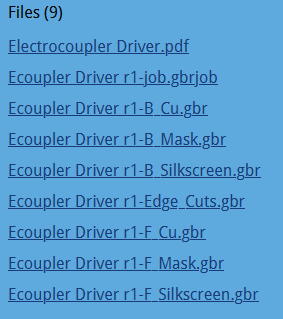
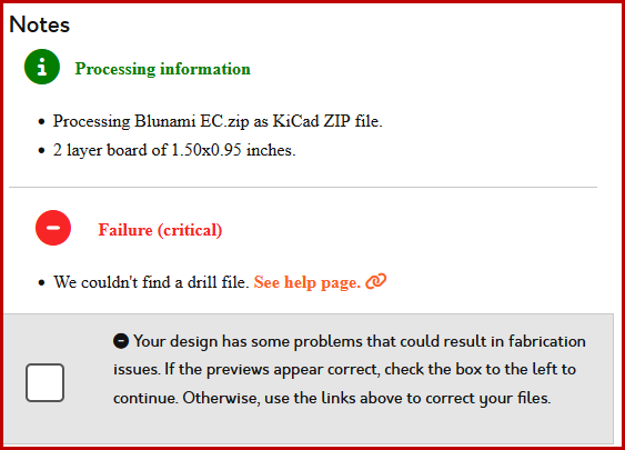
I'm curious how you got them made without the drill file? 
I use 550F for most thru-hole work, and 500F for SMT components. For virtually all the work I do with the soldering station, I use a needle-point tip.
Insert the shortest components and solder them from the other side, that repeat with the next size. I typically keep the boards in a panel and build a bunch at the same time if I can, makes it go faster. You do not have to pre-tin components or the board, at least not in my experience. Trying to tin the board or components would crease all sorts of issues! Yes, solder the leads, then trim them.