While I'm upgrading my SD40-2's in my project in the Hi-Rail section, I also decided to upgrade one of my older Lionel engines to Command Control, in this case the colorful 18018 Southern Mikado, with the Electric Railroad DC Commander (thanks to fellow member GGG). Before getting it hooked up with the other components, I decided to test if the commander itself to see if it reverses correctly.

I put it on the track, and connect the tender tether to the engine's to test in conventional mode. The good news, no shorts or anything bad occurred. The bad news was I couldn't seem to get the engine out of neutral. I flipped the run/program switch, but it stayed in neutral. I followed ERR's wiring diagram correctly - red and blue motor wires, green ground wire, and black hot wire (as per the engine's specifications) - so I can't figure out what's wrong.

image

Attachments

Images (1)
  • image
Last edited by Mikado 4501
Original Post

Replies sorted oldest to newest

Well, here's something a little funky while I'm still waiting to test the Mikado in a Command enviroment.

I've completed one of the two Command upgrades to my SD40-2's. That one, I used the Cruise Commander. The thing is this one did cycle forward/neutral/reverse as per expected in conventional mode.

In addition to testing in the Command enviroment, I'm going to have to look into the engine again just to be sure the wires weren't crossed, and hopefully I didn't blow the DC Commander with that or some stray static electricity...

Last edited by Mikado 4501

The color coding in older Lionel engines was a little dubious apparently.

The blue and red wires in the engine lead to the motor brushes. White leads to the ground, and black goes to the center rail pick ups. So one would figure that the wires to the tender would match (with green being ground in this case).

But no sparks, smoke or explosions yet to the board, so that must be good.

Last edited by Mikado 4501
Mikado 4501 posted:

The real issue here is opening up one of these plugs...if anyone has a good idea how without causing too much damage, that would be great.

image

There is no reason to open this plug.

You can use an ohmmeter to ring out the wires. A sharp meter probe can touch the silver locking tabs shown in the picture and the other probe can touch any of the four wires coming out of the other end of the tether cable.

Write down the color of each wire and its position in the plug as you ring them out.

Last edited by RoyBoy

Fortunately, after testing with my multi-meter, the wiring in the engine and tender was correct, according to ERR's instructions.

However, there was a little bit of instruction I caught on - that the common ground wiring should be on one of the motor mounting screws, not the chassis.

I'm still going to test with a friend's command base and remote later this week just to be sure.

Last edited by Mikado 4501

Okay, after testing in Command mode (thanks to a friend) and using John's program method, the commander still failed to respond.

I also tested it with one of my other commanders (using for the SD40-2's in other project) and still had no response, whereas they all responded in both conventional and command mode.

My common sense is telling me that, in spite of the fact my wiring is as should be for the commander, that not all of the sources of power are getting to the commander. This bewilders me, since I tested the locomotive with both engine and tender tethers connected to the old QSI reverse unit prior to placing the new commander in, and everything worked fine.

*Sigh*

Okay, I've checked the leads again, and noticed something bizarre. When setting my multimeter to checking resistance, the ohms went up when touching both the AC hot lead and the center rail, but also went up when touching the hot lead with the outside ground rails.

Second, when checking resistance to the blue wires to the second motor brush, it didn't respond...until I touched the outside of the can motor instead.

Third, the red wires responded to resistance on both the first and second motor brushes.

I'm not sure what it is about this engine that makes upgrading it so tedious, but it's starting to get on my nerves. I don't get it. Has anyone else upgraded these engines to Command, and if so, have you run into these problems? I'm considering upgrading similar Lionel steamers from the 90's, and I really hope I won't run into these things again.

Last edited by Mikado 4501

Okay, after a trip back to ERR HQ, the DC Commander turned out to be stuck in a single direction, which Ken and the guys at ERR fixed quickly.

But one more issue to sort out before the upgrade is complete...

I hooked the DC Commander to the tender, and the engine reversed as should in conventional mode. The only problem was when I hooked up the RailSounds board to the sound converter (also hooked up to the commander), the bell wouldn't shut off. Also, that the whistle wouldn't activate when I pressed the whistle button.

I'm not quite sure what the problem is, other than that a DC surge seems to be going into the board that won't turn off the bell.

If the Sound Converter is causing the bell to ring all the time, something is wrong with either the wiring or the board.  I've used the Sound Converter in several installations, and unless it's getting a serial command for the offset, it's just passing the AC to the sound board.

You can see the schematic and code used in the Sound Converter in the TMCC Documentation thread, here's a direct link: ERR Sound Converter Documentation and Code.

imageimage

As far as I'm concerned, the wiring is what it should be according to basic instructions, but I'll have to look deeper into the schematic to make sure. The bell not turning off and the whistle not being able to activate tells me unwanted DC surge is going to the conventional board, but that's all I can judge now.

Attachments

Images (2)
  • image
  • image

Hmm...  I just plugged one in on my bench with an old Signal Sounds board, it worked exactly as it should.  When I checked, with no horn or bell being commanded, I see no DC voltage out of the Sound Converter outputs.

Note that the power outputs from the sound converter have to be isolated from ground, if you have one of them grounded, you'll get continuous DC and what you describe.

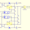
For your reference, this is the output circuit of the Sound Converter.

Attachments

Images (1)
  • blobid0
Last edited by gunrunnerjohn

Update on 6/16:

I decided to replace the conventional sound board with a fresh new one. I couldn't remove the old wires from the hall sensor and its plastic bracket, so I had to solder the blue, green and yellow wires to it instead. I think this works better since the original wires were too short, and I added some flux.

The bad news is when I powered it up, the replacement sound board's steam sounds, whistle and bell failed to sound, just like when I tried to fix the bell problem with the old board, but seemed to make the issue worse...

My gut is telling me that the sound converter needs to be fixed/replaced now, because the amplifier and speaker IS working when I power it up, because I can hear the short audio garble during power up. I could be wrong, but any experience is again welcome. I plan on sending it back to ERR regardless.

Last edited by Mikado 4501

7/11 UPDATE:

After some much rethinking, I decided to go all new sounds for this engine. Mostly to use less space and the tender and make it more convenient in case of a later issue.

One of the issues earlier of why the engine refused to reverse (and reared its ugly head) seemed to be that the motor wouldn't get consistent connection to the ERR commander, and would stay in neutral 99% of the time. And occasionally, it would shift into another direction, but then soon go back to neutral. This happened even after doing the reset commands. And for the record, I tested the motor with DC power from an HO transformer and it moved in both directions perfectly.

I decided that a new engine to tender connection would fix the problem. The old tether was showing its age, but I didn't want to open it up. I see that ERR offers tether connections (4 and 2 pin) which should fix this problem. Correct me if I'm wrong, though I'll be needing new tether anyways to connect to the headlight and smoke unit.

Last edited by Mikado 4501

George, what would he need a separate wire for the cab light for?  There's no place on the TMCC board to independently control it.  If he has a cab light, I'd just power it from track power as most TMCC stuff did.

I normally use seven wires of a tether for TMCC, but since I use the MTH tethers, I double up one of the wires for the smoke as they're pretty small.  That gives me a couple of spares.  In the rare instance that I have a front electrocoupler, I use one of the spares for that feature.

gunrunnerjohn posted:

George, what would he need a separate wire for the cab light for?  There's no place on the TMCC board to independently control it.  If he has a cab light, I'd just power it from track power as most TMCC stuff did.

I normally use seven wires of a tether for TMCC, but since I use the MTH tethers, I double up one of the wires for the smoke as they're pretty small.  That gives me a couple of spares.  In the rare instance that I have a front electrocoupler, I use one of the spares for that feature.

Your correct, I was thinking repurpose of smoke output.  But he has smoke.  G

Add Reply

Post

OGR Publishing, Inc., 1310 Eastside Centre Ct, Suite 6, Mountain Home, AR 72653
800-980-OGRR (6477)
www.ogaugerr.com

×
×
×
×
Link copied to your clipboard.
×
×