Another fantastic educational and useful thread.
Thanks,
John


|
|
Another fantastic educational and useful thread.
Thanks,
John
@Rod Stewart posted:Hokie 71; this is a very neat idea IMO. I would have never thought of that! I have never had an issue with removing excess wires from the underfloor, nor do I disconnect anything from the trucks, but your idea should help to save time converting cars equipped with these light sockets. I like it!
If I remember correctly, first one I did was a full vista dome (your instructions inspired me
), I followed MTH disassembly instructions and they start with disconnecting the truck wires. this did allow me to have an easier time fooling with the wires under the seats to make the connections these need. Sadly, I did not get the idea to reuse a socket until the second regular car.
Since I like to locate the module either in the vestibule area, or a restroom, I would likely still put MF pigtails in the DC module-to-led strip wires, and hardwire the re-used light socket to the module AC pads. But that's just me, a personal preference thing.
I agree with preferring vestibules and restrooms but I ran into a few issues and starting using double sided foam tape to the ceiling. Pray it lasts as long as I am around. It is amazing how it is not visible for regular viewing. Since the led strip and the power supply were both on the ceiling, I conserved my limited stash of JST pigtails. Now that I have more pigtails from your excellent kits, I may start adding them since it is a good idea.
Question: For the other original car lights, do you just clip their wires flush to the seat frame? Or?
I have been able to simply remove the other bulbs and leave the bases and the holders in place. the led strips fit into a small gap between the clear plastic "bridge-holders" and the roof. Bottom line is I don't touch any of the native wires.
Rod
Hokie 71; this is POSITIVELY BRILLIANT! I wish we would of had this conversation say about 20 sets of car conversions ago! I think you have probably just re-written the procedure book for doing a car conversion. I can hardly wait to do my next set just to try this out.
The part I especially like is there is no need to change the original wiring. That will sit well with the "purists", (though I certainly don't fit in that category heh heh!) ![]()
TAKE NOTE ALL YE WHO ASPIRE TO CONVERT PASSENGER CARS TO LED LIGHTING:
Hokie71's way of doing it looks like the fastest and easiest way to git 'er done! My hat's off. ![]()
Rod
So taking Hokie71's idea to the next logical step, I think it would be kinda neat to pre-make a batch of modules up with a converted bulb socket and say 4" pigtail solder to the AC inputs, and the female end of the JST 1.25 pigtails soldered to the DC outputs. You could also pre-soldering the male end of the JST pigtails to the led strip, and you're all set. This would pretty much eliminate having to solder anything in the car while doing a conversion, which is bound to save time in the end!
And I just happen to have a large box of car light sockets and bulbs sitting around under the bench, that I had no idea why I was keeping. Betcha can't guess where they came from??
Is this a great forum or what? ![]()
Rod
For those folks who may not be familiar with operation of the observation car marker led boards, attached is a summary of what it does and how it to use it. Sorry I did not post this earlier! ![]()
Rod
Here just for reference is the Aug 2021 topic that deals with the care and feeding of the observation car marker led boards: ![]()
Rod
I completed my first board and car. I used Hokie 71’s light socket method on this RailKing car and the lights look great! Many thanks John, Rod, Hokie 71!!!

Ordering from Digi-Key. They are out of the LM317TG. Which equivalent should I order?
One more Digi-Key sub, 200 ohm trim pot. they only have 12. what could substitute for that?
If DK have the LM317T (no G) that will work. If no stock at all they will often direct you to another site that stocks them. How many do you need? They are readily available on ebay from offshore but delivery is about 2 weeks.
regarding the the pots, what board rev are you using? If its the original R1.0 that will accept the 3362P top adjust, or the 3362S side adjust, or he 3296P end adjust precision pot.
Rod
I was going to order the latest rev of the board.
I sent you an email about kits. that may fix my problems.
Hi. I have some of the v1 boards I need to build now that I have time. I saw the lm317 and pot alternates above. The choke and resistor are a bit hard to find on the original part list. Any suggestions on those? Thanks!!
@NYCBuffalo posted:Hi. I have some of the v1 boards I need to build now that I have time. I saw the lm317 and pot alternates above. The choke and resistor are a bit hard to find on the original part list. Any suggestions on those? Thanks!!
How many of each do you need? Maybe shoot me an email and I can fix you up. Email in my profile.
Rod
I have bought and used several of these kits for lighting passenger cars. I'm now considering using these to light some bldgs with the LED strips. The bld already has a transformer connection for some incandescent bulbs, so would just tap into that to provide power.
With that said how many LEDs in the strip can I feed with one circuit board without getting too hot? I have a large bldg where I would like to use around 60 leds. If each LED uses around 20ma, then that would be around 1.2A. I may be able to add a heatsink or I could split the LEDs up into 2 groups of 30 and use 2 circuit cards. Will the little pigtails included in Rod's kit handle the amperage?
Ken
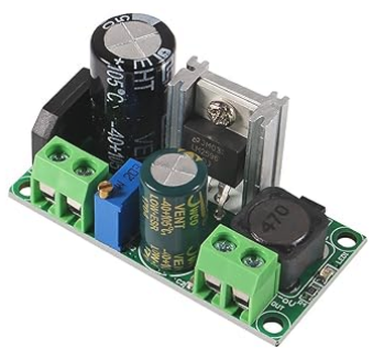
Ken, if you're trying to run a bunch of LEDs at full intensity, these constant current modules aren't what you need. You should be shopping for a variable voltage AC-DC buck module. Search for these on Amazon, four for $12.99 shipped Prime for free.
UMLIFE 4PCS AC/DC to DC Step Down Buck Converter AC 5-30V DC 5-48V 24V 36V 48V to DC 2.5-35V 12V Voltage Regulator Board 2A Adjustable Volt Power Supply Module

Thanks John. I actually have one of those buck converters and will use in this building. I still have quite a few kits of yours/Rod's and was looking for other possible uses since I have no more passenger cars to convert.
Have you considered using strip leds, same as used in pass cars? I recently did a large 2 story RK station that used 19 sections, 57 leds, and lit it with one of the lighting module kits using a 12 ohm resistor for R1. That gives about 110 ma max output and worked like a charm.
Rod
Here's a picture of the above station.

There are led strips under both sides of the front door canopy, under the full length of the back canopy, and full length inside above the front 2nd story windows. I thought it turned out pretty well. YMMV.
Rod
Rod, that is the exact building I am modifying by putting LED strips under the front and back canopies. I was going to use a total of 20 sections, 60 LEDs. Since I have the converter John mentioned, I will go ahead and use that.
I like your Miller Engineering sign on top. Did you feed that with a separate feed from a 4.5V DC supply or did you use some type of circuit to convert from AC to DC?
Ken
@Kenjr posted:Rod, that is the exact building I am modifying by putting LED strips under the front and back canopies. I was going to use a total of 20 sections, 60 LEDs. Since I have the converter John mentioned, I will go ahead and use that.
I like your Miller Engineering sign on top. Did you feed that with a separate feed from a 4.5V DC supply or did you use some type of circuit to convert from AC to DC?
Ken
Interesting coincidence re the same building. ![]() The Miller sign is fed off the same 14VAC supply to the building, using a AC-DC converter board with a fixed LM7805 Vreg. Works just great.
The Miller sign is fed off the same 14VAC supply to the building, using a AC-DC converter board with a fixed LM7805 Vreg. Works just great.
Rod
@Kenjr; did you get your RK Station led mod done? Just curious. ![]() Pictures would be good heh, heh.
Pictures would be good heh, heh.
With the holidays and travel, still working on it. I also ordered the union Station sign and will install.
I'll get a couple of pics tomorrow
Finally a couple of pics. I had to dial down the voltage on converter for the LED strip lighting to better balance with the existing lights.


Nice ken; that turned out very nice indeed! And that Miller UP sign looks perfect up there. All good. ![]()
Rod
Looks great, Ken!
Not being an electronic wiz, I'm curious about the differences between the circuit used in the kits vs the buck converters that John recommended for buildings. I gather one limits current and other adjusts voltage? Both allow me to drive some 12V LED strips from my transformer input and adjust brightness. Are there any advantages of using one vs the other, maybe smaller size or higher capacity? I did an experiment with a kit and hooked up 60 LEDs on a strip and powered up from transformer near full brightness and the regulator only got slightly warm to the touch after 1 hour.
@Kenjr posted:Not being an electronic wiz, I'm curious about the differences between the circuit used in the kits vs the buck converters that John recommended for buildings. I gather one limits current and other adjusts voltage? Both allow me to drive some 12V LED strips from my transformer input and adjust brightness. Are there any advantages of using one vs the other, maybe smaller size or higher capacity? I did an experiment with a kit and hooked up 60 LEDs on a strip and powered up from transformer near full brightness and the regulator only got slightly warm to the touch after 1 hour.
The heat dissipated by the 317 is a direct function of the voltage loss dissipated through it. For instance if you use 18VAC track power rectified to filtered DC at about 24VDC and the 317 regulates that down to about 9VDC; thats a 15 volt loss. For 60 leds running as 20 sections of 3, at say 3ma per section, thats a total of 60ma. So the power dissipated is 15 x .06 - 0.9 watts; almost a watt. That 317 with no heat sink will get pretty toasty.
OTOH if you are using say 12VDC accessory power, the loss is only about about 3V and the power is 0.18 watt, and the 317 will be quite cool. The lighting module kits work well for loads up to about 100ma (with R1=12R). Thats what I am using on my MTH station to light 19 sections of leds, 57 total, using 12VAC accessory power. It does not get hot at all, though I never actually figured out the power loss.
For higher regulator load applications like 1/2 amp or more, you are likely better off with an inexpensive buck converter. They are generally switching type voltage regulator, so the heat generated is considerably less for the same load. Most are DC to DC, so you would need a bridge rectifier and filter cap if the supply is AC. AC to DC buck converters are also available.
Rod
Thanks Rod. So does that mean I can use 12VDC to power the passenger board kit? I have both 15VAC and 12VDC available to power buildings, so wondering which would be better.
After I wrote the last response I realized I could hook up directly to 12VDC power just would have no ability to dim the LEDs. If I can just use the kit to drop the 12VDC to 9vdc, that would be great.
@Kenjr posted:After I wrote the last response I realized I could hook up directly to 12VDC power just would have no ability to dim the LEDs. If I can just use the kit to drop the 12VDC to 9vdc, that would be great.
Yes the lighting kit will work with 12VDC supply no problem. And you should be able to dim the leds satisfactorily to where you want them. If for some reason they are not bright enough you can use the 15VAC supply just as well.
If the board won't put out the power level for the brightness you need, switch R1 to a 12R resistor and you are good. If a 12R resistor (or something close) is not handy, two 24R in parallel will work. ![]()
Rod
@Kenjr posted:After I wrote the last response I realized I could hook up directly to 12VDC power just would have no ability to dim the LEDs. If I can just use the kit to drop the 12VDC to 9vdc, that would be great.
Cheaper than the kits would be to wire about 2 or 3 diodes in series with your 12v DC power source and lights which will drop the output to 8 to 9.5 volts. Diodes are dirt cheap.
Careful how low a voltage you go to with those diodes. At 7.5 volts or less standard strip 12V leds make no light at all. Don't take my word for it; go ahead and give it a try! ![]() And at 8V they use a measley 0.28ma per 2" section.
And at 8V they use a measley 0.28ma per 2" section.
The useable range for passenger car lighting IMO is about 8.8 to 9.4V. And the best way to get the intensity you want is probably with an adjustable regulator source. That's just me.
Rod
I tried the 12VDC supply and everything works great. Brightness is just right.
Access to this requires an OGR Forum Supporting Membership
