
I took the liberty of moving grj's original files for this project over to a new topic just to make them easier to find. The original topic started in late 2016 and is some 7 pages long; these files are found on page 5.

The only thing I have added to this is my user notes in Word format as an attachment. The gerber zip file is also attached below. I want to emphasize that grj is the sole creator of this circuit and these original files! 

mceclip0

mceclip2

mceclip3


Attachments

Last edited by Rod Stewart
Original Post

Replies sorted oldest to newest

I would like to mention how well this board works.  To date, I have built and installed 30 of these modules with no failures.  Further, I would emphasize(as recorded in Rod’s user notes) that a simple increase in value of R2(brightness adjustment) to say, 500 up to 1000, will allow for dimming the lighting even more, for those who prefer that effect.  For my taste, 500 was the preferred value.

The pcb can be ordered here(in sets of three)from Osh Park:  DIY-GRJ-JWA Passenger car lighting PCB  I don’t have an off shore link for the pcb, but others do.  You will need to set up an account to order, but once on this site that will be straight forward.  I ordered my parts from Digikey searched individually then add them to your cart.  Of course you may select any other distributor of your choice, including off shore sources.

Due to the freely given advice from GRJ, Rod Stewart and others, I decided to go ahead and attempt this PCB build, even though a total novice at electronics.

My question is regarding the Voltage Regulator (LM317TG) - it arrived from Digikey in a foil bag with conspicuous warnings about harm to the component from static electricity. What do you fellow forum members do in this case? Antistatic mats and/or spray? Wear a grounding device? Not wanting to invest a whole lot in antistatic measures, may  I just ignore the warnings and go ahead? Would everything still work?

Many thanks for the help. 

Glad to see you are giving one of these projects a try, hope all goes well and you find it enjoyable.

I don't know about the others, but I have never taken any special precautions. I do just as you suggest, ignore the warnings and go full speed ahead. I have worked on many computers over the years, dabbled with electronics and other stuff and never zapped anything. Well that is  from just handling something anyway. (Improper connections, wrong voltages, etc. are another story...)

However, if you are working on carpet or something that can easily generate static, that could be a bit different. If you often get zapped when you touch something in your work area, then some precautions might be justified. Wrist grounding strap or something like that. 

Last edited by rtr12
Bob "O" posted:

Due to the freely given advice from GRJ, Rod Stewart and others, I decided to go ahead and attempt this PCB build, even though a total novice at electronics.

My question is regarding the Voltage Regulator (LM317TG) - it arrived from Digikey in a foil bag with conspicuous warnings about harm to the component from static electricity. What do you fellow forum members do in this case? Antistatic mats and/or spray? Wear a grounding device? Not wanting to invest a whole lot in antistatic measures, may  I just ignore the warnings and go ahead? Would everything still work?

Many thanks for the help. 

Those regulators are practically bulletproof, no worries.  I've used hundreds of them (actually thousands), and I don't do any special handling.  Digikey ships stuff like connectors in similar bags at times, and I'm sure they're not static sensitive!

@Rod Stewart posted:

I took the liberty of moving grj's original files for this project over to a new topic just to make them easier to find. The original topic started in late 2016 and is some 7 pages long; these files are found on page 5.

The only thing I have added to this is my user notes in Word format as an attachment. The gerber zip file is also attached below. I want to emphasize that grj is the sole creator of this circuit and these original files! 

mceclip0

mceclip2

mceclip3


Can I substitute the item below for C1? Digi-key does not have ECA-1VM471 in stock.


Digi-Key Part Number
P5554-ND
 
Manufacturer
Panasonic Electronic Components
 
Manufacturer Product Number
ECA-1VHG471
 
Supplier 
Description
CAP ALUM 470UF 20% 35V RADIAL

Digikey cart share

I don't know how long Digikey retains a "shared cart".  Above link should get you to a starting point for the parts list for this project including the original and alternate capacitor (choose 1)- presumably at some point the original capacitor will return to in-stock status and it's a bit less expensive.  The idea is you simply click on above link and it loads your shopping cart for a quantity 1 order.  Edit the quantity for each item.  Who knows if this saves time but I've always thought this was a neat feature from DigiKey.

@TedW posted:

The pcb can be ordered here(in sets of three)from Osh Park:  DIY-GRJ-JWA Passenger car lighting PCB  I don’t have an off shore link for the pcb, but others do.  You will need to set up an account to order, but once on this site that will be straight forward.  I ordered my parts from Digikey searched individually then add them to your cart.  Of course you may select any other distributor of your choice, including off shore sources.

Hi, I have made similar boards to these and put in many of my coaches, this looks cleaner than what I have done. My question, when ordering the PCB, you mentioned ordering in sets of three, is that automatically done, say one order @ $3.80 / 3 PCBs? I want to make sure I don't end up with 3 times what I need.

I have never ordered these before, hope I don't sound to stupid.

Ray

@Rayin"S" posted:

Hi, I have made similar boards to these and put in many of my coaches, this looks cleaner than what I have done. My question, when ordering the PCB, you mentioned ordering in sets of three, is that automatically done, say one order @ $3.80 / 3 PCBs? I want to make sure I don't end up with 3 times what I need.

I have never ordered these before, hope I don't sound to stupid.

Ray

When you order boards from OSHPark, they are in quantities of three, that's the way they do business.  It's clear on the website the quantity you are getting.  Right after you drop the ZIP file with the Gerber files in it on the page they calculate the cost and show you this notice.  You can order three, six, nine, etc., they come in groups of three.

Attachments

Images (1)
  • mceclip0
@TedW posted:

Here’s a sample order as an example, choose the 2oz copper option for the same money and more current capability.

Actually, given the fact that the whole circuit only handles milliamps, more current capability is a moot point.

That being said, I actually do select the 2oz copper option, but for a different reason.  It's also .8mm thick instead of 1.6mm thick!  The thickness is why I pick it, no need to have the board any bulkier than necessary.

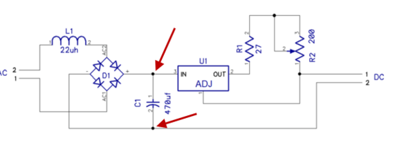
A question about the 470uF capacitor recommended in GRJ's circuit.

I have been greatly helped by contributors to this thread and thank them for my being able to convert 8 passenger cars to LED's. So far each PCB I have built has worked well. There is some minor flicker at very slow speeds over some of my older switches, but vastly better than the old incandescent bulbs.

I just acquired 2 new passenger cars (Lionel 1927620) that are already equipped with flicker-free LED lighting. I have noted that on track power-up, these cars take several seconds to reach full brightness and on power-off, they decay very slowly, perhaps over 3 full seconds. Is that due to a different capacitor or some other function?

I still have 7 more Polar Express cars to convert and if I can do a simple upgrade on the capacitor, I would do that to get the longer decay time. Of course, it would have to be the same pin spacing to fit GRJ's board and not be too much bigger.

Thanks for all the expertise freely shared on this Forum!

Bob

The capacitor is simply a storage device, the larger the capacitance, the more energy it can store.  The intensity of the lighting (and thus the current draw) will determine how long the energy in the cap lasts to keep the lights on.

Truthfully, I really have not had issues with the 470uf value of the cap, even at slow speeds over switches.  If you're seeing issues, I'd be checking the integrety of the pickup rollers and wheel axle wipers that supply the power.  Normally with passenger cars over switches, at least one roller should be on the powered track, and any power interruptions would be very small.  What kind of switches are you seeing this effect on?

The amount of storage and the current setting directly affect the hold-up time for the lighting.  The dimmer you run them, the longer they'll last during power interruptions.

Here's a 1,000uf cap that  will drop in and double the capacitance.  It is taller than the 470uf cap, but the same lead spacing and diameter.

Rubycon 35PK1000MEFCT810X20

Today, I got around to building a PCB with the 1,000 uf cap. But I had a frustrating afternoon. Could not get it to work and wonder if I messed up somewhere. I know it's a long shot, but can you tell from the photo where I went wrong?

What happens when I input 17.5 - 18 V AC: I get about 6 - 6.5 V DC out, measured at the output terminals. This output won't light my strip of LEDs (3528 ribbon style, rated for 12V DC.) Turning the pot makes no difference. If I apply DC current to the same LED strip directly, ie not through the board, it lights just fine, even at 6 V DC, although it is fairly dim at that voltage. Should I swap out the 1000 uf cap for the 470 uf and see if that works?

(I checked and re-checked everything I could think of for over an hour. Ready to jump off a bridge but my wife poured me a big glass of Malbec and now I am feeling better.)

Bob

Attachments

Images (1)
  • 7BE4B84B-4949-4E7B-ADFA-1198D80530B5

Bob; it's doubtful the cap is the problem IMO. Those boards have all worked perfectly for me, even with 1000 uF caps installed. I would bet the problem is the 317T since everything else looks good. From the pix the center pin soldering looks a bit suspicious, though from the bottom it might be just fine. I would recheck that for sure. If that doesn't solve the problem i would cut out the 317 and put in a new one. They are pretty cheap after all. Several months back another gentleman was building a few of these and had some troubles. It turned out the pack of bulk 317's he bought had several defective ones. Seems hard to believe I know, it sure seemed odd to me. Don't think I have ever had a bad one. Worth checking.

Rod

@Rod Stewart posted:

Bob; it's doubtful the cap is the problem IMO. Those boards have all worked perfectly for me, even with 1000 uF caps installed. I would bet the problem is the 317T since everything else looks good. From the pix the center pin soldering looks a bit suspicious, though from the bottom it might be just fine. I would recheck that for sure. If that doesn't solve the problem i would cut out the 317 and put in a new one. They are pretty cheap after all. Several months back another gentleman was building a few of these and had some troubles. It turned out the pack of bulk 317's he bought had several defective ones. Seems hard to believe I know, it sure seemed odd to me. Don't think I have ever had a bad one. Worth checking.

Rod

Rod,

Here is the bottom of the PCB. The regulator is from DigiKey, LM317TG. I am a novice at this type of soldering. However, I have built about a dozen of these, using the 470uf and they are all installed and working flawlessly. Nevertheless, I am no expert!

The cap should make no difference in the output current.  That is a LM317 regulator, right?  It looks OK visually, but I can assure you that many people have built the same board and are using them, so something is amiss.

What voltage to you get measuring directly across the capacitor at the two arrows?

John,

The voltage across the cap, with 17.5 V AC in, is 2.3V DC. I have no idea if that is good or bad.

Thanks to both for your prompt replies.

Bob

Attachments

Images (2)
  • 1C4215A3-F1C2-49B3-A7BB-268A6C9591C2
  • 37346691-4420-416A-A992-76540B3178A9
@Rod Stewart posted:

For the heck of it why not put in one of your 470 uF caps and see what happens?

Rod

I wonder if the cap is actually defective?  I'd pull it and put one of the 470uf ones in and see if it works.

Rod and John,

I started from scratch and built a new board with all new components, paying attention to my soldering and using a 1000uF cap again. No luck, didn't work. So I pulled it and put in a 470uF cap and everything works fine!!

Go figure. I have lots of the 470 caps, so I will stick to those for now.

Thanks for helping.

Bob

Obviously, something is going on with the caps, are they 35V or greater rating?  If you got them from my link on Digikey, I'd be surprised if they're bad!

@Rod Stewart posted:

Bob, that's very strange. Glad it's solved though. I wonder if you got a bad batch of 1000UF caps?? If they are Digikey you would have some recourse to get them replaced. If they are offshore, hmmm, good luck!

Rod

They are Digi-Key and yes, John, I used your link. I ordered only 10 of them, so no big expense. Not sure I could provide any evidence to Digi-Key that they are faulty. It is much more likely that I did something incorrectly, twice, but no idea what.

No doubt I will try and use the 1000uF caps in the future but going to give it a break for now. More later if the third attempt succeeds. With your combined experience, Rod and John, that these are reliable devices, I am satisfied that it must be mysterious human (mine) error.

Appreciate your time on this.

Bob

Attachments

Images (1)
  • 83778AB7-79FC-4A31-B17E-9C9A9D12CC4A

They looked to be installed in the correct orientation, not much else you can do to those caps to cook them in that circuit.  I looked at the picture again, and the only thing that comes to mind is you connected the AC to the wrong connector.  Noting that you used the same style connectors for both AC and DC, if you connected AC to the DC side, you would get some very funny readings!

FWIW, I always use different connectors for power and signals on anything I build, that way it's not possible to connect the power to the wrong place.

@Rod Stewart posted:

Bob; my curiosity is burning; have you tried swapping out one of the 1000 uF caps for a 470 in either of the failed boards??

Rod

Rod, yes - my second build was with the 1000uF cap and when it did not work, I de-soldered it, removed and replaced it with a 400uF cap. The operation was then perfect.

They looked to be installed in the correct orientation, not much else you can do to those caps to cook them in that circuit.  I looked at the picture again, and the only thing that comes to mind is you connected the AC to the wrong connector.  Noting that you used the same style connectors for both AC and DC, if you connected AC to the DC side, you would get some very funny readings!

FWIW, I always use different connectors for power and signals on anything I build, that way it's not possible to connect the power to the wrong place.

John, good tip on using different connectors. To avoid that blunder of mixing up the AC input with the DC output, I checked and re-checked with the markings on the spare PCB, as seen in the first photo.

Both you guys are awesome in the interest taken in my problem. That's what makes this Forum so valuable!

Bob

I'm stunned that a 1,000uf cap fails and a 470uf cap works, that makes no sense!  I've actually tested that circuit with a 2,200uf cap to see how long it would hold the LED's up, and it didn't change the operation, and it never even occurred to me to think it might!

FWIW, my previous production run of the lighting boards had a 680uf cap, that worked just fine.  That was going to be my standard going forward, but I couldn't get them for the latest production.  The electronic parts shortage is biting everywhere.  I had to settle for a 470uf cap again, the largest value I could get in the form factor for the production board.

I'm stunned that a 1,000uf cap fails and a 470uf cap works

@Rod Stewart posted:

Bob, I too am shocked that the cap switch solved the issue. Clearly the smoking gun is the 1000uF cap

I couldn't stop thinking about this. So I built another board but did not solder in the cap. Instead, I inserted first the 470uF and bent the legs to get good contact, then applied power - working. Then I put in the 1000uF cap and bent the legs and it worked too!!

So you are both right - nothing wrong with the caps. I must have erred somewhere, twice, when soldering the components on both the first 2 boards. Reminds me of the saying, "I learn from my mistakes and can repeat them exactly."

I will test all the caps that I have left on this temporary board and maybe try to test the first caps that got blamed for the failure. I nipped off the legs to de-solder them but will cobble something up.

And the decay in the lighting after power off is noticeably longer with the 1000uF caps. Happy camper here. Thanks to both.

Bob

IMG_2990IMG_2992

Attachments

Images (2)
  • IMG_2990
  • IMG_2992
@Bob "O" posted:
And the decay in the lighting after power off is noticeably longer with the 1000uF caps. Happy camper here. Thanks to both.

Obviously that would be the case when everything is working.  FWIW, I found that even my original 330uf cap for my lighting modules was sufficient to kill almost any flicker.  I increased it to 470, and briefly to 680 for the production runs.  With the component shortages, I can no longer get the 680 caps, so I'm back to the 470.

Quick question on this subject.  If I have a strip of led lights, and I just hook it up right to a 9 volt dc battery, will it lit up without any other circuitry?  I have a Halloween display item I would like to light up but not much time to build anything fancy electronically, but I could certainly find time to quick wire up a battery and a switch.

I hasten to add, with the ampacity of the typical 9V Alkaline being 400 MAH, if you run have 40ma of draw, they'll only last 7-8 hours.   A simple variable DC supply like this 120VAC->9VDC Module at Digikey for $4.48 would be a much better choice.

Datasheet for LD05-23B09R2

Thanks John,  thanks @Rod Stewart.  This is for a display that happens 1 night year for about 3 hours.  2/3 intensity for 8 hours is perfect!

OK you can cut on the red line below at any place you see a pair of oblong copper pads. Each 2" section of the strip contains 3 leds and one resistor (the black thing) in a small series circuit. You have to cut only at the pads, in 2" increments.

So lets say you want 10 sections, 30 leds; just cut at the 10th pair of pads. Each section of 3 leds will draw about 3-4 ma of power, so judge accordingly. And yes you can solder wires onto those pads. Observe polarity when hooking up the battery.

leds-cut

Rod

Attachments

Images (1)
  • leds-cut
@Rod Stewart posted:

I took the liberty of moving grj's original files for this project over to a new topic just to make them easier to find. The original topic started in late 2016 and is some 7 pages long; these files are found on page 5.

The only thing I have added to this is my user notes in Word format as an attachment. The gerber zip file is also attached below. I want to emphasize that grj is the sole creator of this circuit and these original files!

mceclip0

mceclip2

mceclip3


That you for your help & information however I downloaded your notes & printed out & then downloaded the 7 pages of Gerber files & tried to print but no program in my new computer would allow me to open & printed these pages. Wondering what prgram you use to open & print these files. Your help is greatly appreciated

Another option is OshPark domestically. Their price per board is higher, but if you only need a few that would work. I beleive their price is about $1.25 a board in batches of 3. Again as grj says you upload the gerber zip file to their site and go from there.

If you only need 10 or 20 boards I can mail them to you inexpensively. Shoot me an email if interested. I can also help with placing a board order for you for delivery to your address if needed.

Rod

@ffjon posted:

I hope I don't cause any ill feelings but I was looking at a low cost alternative for installing LED strip lighting and came across this video on YouTube:

How To Add LEDs To Lionel MPC Passenger Cars

His "design" uses just capacitor and voltage regulator. I'd appreciate any thoughts on this approach.

No hard feelings here, you're free to use whatever technique you find useful.

A couple of points that you don't get with this method.  The first is intensity adjustment, and there is also the lack of DCS compatibility.  Those cars with the huge cap right after a full-wave bridge will hammer the MTH DCS track signal.

@ffjon posted:

I hope I don't cause any ill feelings but I was looking at a low cost alternative for installing LED strip lighting and came across this video on YouTube:

How To Add LEDs To Lionel MPC Passenger Cars

His "design" uses just capacitor and voltage regulator. I'd appreciate any thoughts on this approach.

Jon

Very interesting but I like the idea of the adjustable pots on gunrunner Johns site, but that was very good to know. Thank you for your help.

@ffjon posted:


...

His "design" uses just capacitor and voltage regulator. I'd appreciate any thoughts on this approach.

i dont think so

By my reckoning, your linked youtube video shows "just" a capacitor and a bridge-rectifier (not a voltage regulator).

To each his own but I think the photo (clipped from your video link) is RIDiCULOUSLY bright!  GRJ's module allows brightness control...amongst many other benefits.

Full disclosure, I have absolutely no business relationship to GRJ's goings ons and arguably we disagree here on OGR more than we agree!   Also, you get support from fellow OGR participants with his module which is absolutely priceless IMHO.

Attachments

Images (1)
  • i dont think so
Last edited by stan2004
@stan2004 posted:

By my reckoning, your linked youtube video shows "just" a capacitor and a bridge-rectifier (not a voltage regulator).

To each his own but I think the photo (clipped from your video link) is RIDiCULOUSLY bright!  GRJ's module allows brightness control...amongst many other benefits.

Full disclosure, I have absolutely no business relationship to GRJ's goings ons and arguably we disagree here on OGR more than we agree!   Also, you get support from fellow OGR participants with his module which is absolutely priceless IMHO.

Stan, I suspect he's also driving the LED's way past their rated 12VDC spec.  He has a bridge rectifier and a pretty large 4700uf cap, so I'm guessing unless the voltage on the tracks is in the 9-10 VAC range, the output DC is way over 12V.

Live and Learn though John, redoing a batch would cure the desire for too simple.

I am hoping to actually be running MY trains by this time next year, the new house is likely 3 months from completion and I can begin to finish the packed pax cars with your LED boards. I have been doing club trains for 13 months as wait for my place to be finished. I think I can build a board in like 5 minutes now, so production times will not be an issue.

Finding the boxes with all of MY components will be a treasure hunt for sure.

@Rod Stewart posted:

Another option is OshPark domestically. Their price per board is higher, but if you only need a few that would work. I beleive their price is about $1.25 a board in batches of 3. Again as grj says you upload the gerber zip file to their site and go from there.

If you only need 10 or 20 boards I can mail them to you inexpensively. Shoot me an email if interested. I can also help with placing a board order for you for delivery to your address if needed.

Rod

Hi Rod, being new to the Forum I am not sure how to send you a email. Would like to ask a couple questions. So I need some guidance on how to shoot you a email. Thanks for your help.

@DCS213 posted:

Hi Rod, being new to the Forum I am not sure how to send you a email. Would like to ask a couple questions. So I need some guidance on how to shoot you a email. Thanks for your help.

Click on the profile name, the public profile will pop up, any public email address will be there.

For example...  Email obscured for privacy concerns.

Attachments

Images (1)
  • mceclip0

Rod, Have either you or GRJ thought of offering complete DIY kits of these modules? Complete kits (less LED strips) including: boards, parts  and an instruction sheet with an illustrated wiring diagram? Perhaps in a minimum of 12 or even 20 kits per package? It would be perfect for those of us who enjoy assembling, but HATE ordering through the mazes of DigiKey or Mouser catalogs, or, worse yet online from China!

@hokie71 posted:

Rod, very well done.  I may have missed it but where does the LED board on page 6 come from?  Seems I saw it in a previous post but can't find it.  Thanks.

I should have probably elaborated on that point. I posted those boards in a topic back a few months ago, and they really make obs car marker lighting slick.

I have the bare boards available and I charge $.50 a piece for them. I can also make the gerbers available for anyone who wants to order them from OshPark or wherever.

I should add here that several of these boards can be shipped very inexpensively in a regular envelope marked “Non-machinable”. I have shipped them this way a couple of times.

Rpd

Last edited by Rod Stewart

Following this thread over time, brings a lot of information about the DIY passenger car lighting module.  Many of you know that I have built and used this module for all my passenger cars, thus developing a modest amount of experience in the build.  To that end, I have put together a short instruction sheet to demonstrate the relative ease in putting together this very useful lighting PCB.  Please use it for help in not only the PCB build, but also to see for yourself if it is something you may want to try.  The instructions are basic, if I am not clear in the instructions, or, you have any questions, please do not hesitate to shoot me an email(in profile)  Give it a try!!

Attachments

Last edited by TedW
@TedW posted:

Following this thread over time, brings a lot of information about the DIY passenger car lighting module.  Many of you know that I have built and used this module for all my passenger cars, thus developing a modest amount of experience in the build.  To that end, I have put together a short instruction sheet to demonstrate the relative ease in putting together this very useful lighting PCB.  Please use it for help in not only the PCB build, but also to see for yourself if it is something you may want to try.  The instructions are basic, if I am not clear in the instructions, or, you have any questions, please do not hesitate to shoot me an email(in profile)  Give it a try!!

@TedW sent me this file a couple of years ago. As a complete novice at soldering and PCB building, it was a perfect stimulus to get me going. A must read for anyone thinking of doing this. Thanks @TedW.

Bob

@Rod Stewart posted:

Posting the latest update to my lighting installation tips, in pdf format in case it's helpful to anyone.

Rod

A gentleman who recently bought some builtup modules from me had a few questions regarding AC wiring and led strip attachment. So I figured it would be a good idea to clarify things a bit in the installation tips document; revised and pdf copy attached below.

Rod

Attachments

Add Reply

Post

OGR Publishing, Inc., 1310 Eastside Centre Ct, Suite 6, Mountain Home, AR 72653
800-980-OGRR (6477)
www.ogaugerr.com

×
×
×
×
Link copied to your clipboard.
×
×