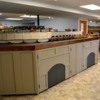
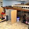
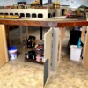
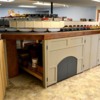
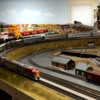
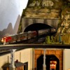
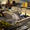
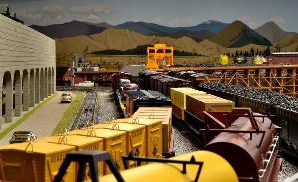
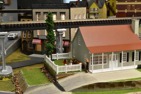
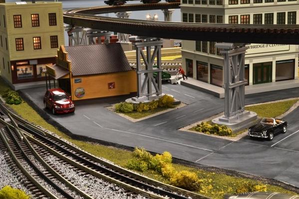
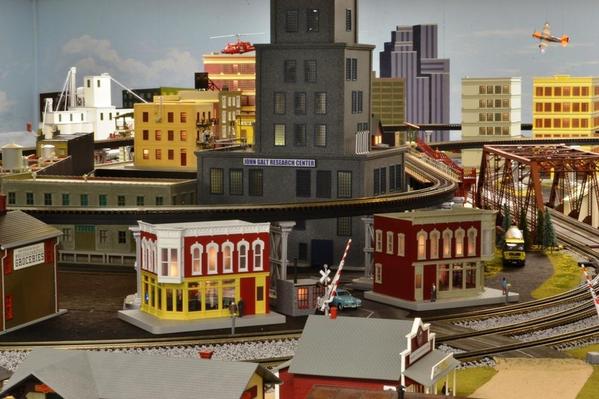
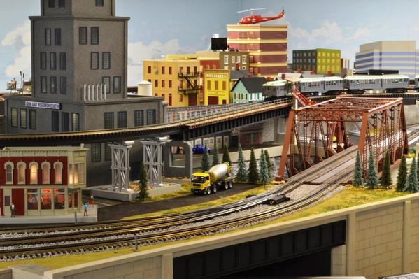
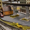
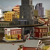
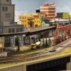
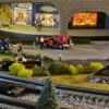
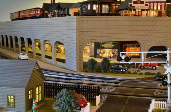
Very impressive!
Alex...this looks just fantastic! I dabbled around with my subway about a year ago but stopped working on it and have been busy with other projects. Your wonderful effort is going to get me started again!
Thanks,
Alan
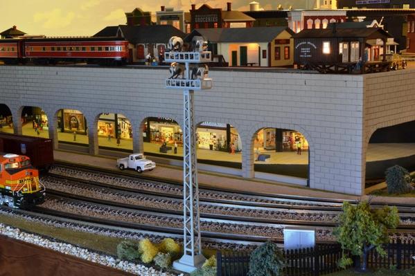
Wow! What a great idea. The subway mall is an awesome addition.
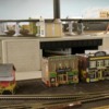
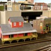
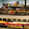
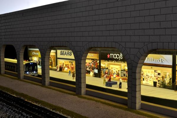
WoW. I actually did a double take when I glanced at the Sears and JcPenny storefronts. The realism is outstanding!
It truly looks like you are looking through arches toward the fronts of the stores.
As always, great work!
Brian
Zett, Luvtrains, Brian –
Thank you for your nice comments and approval!
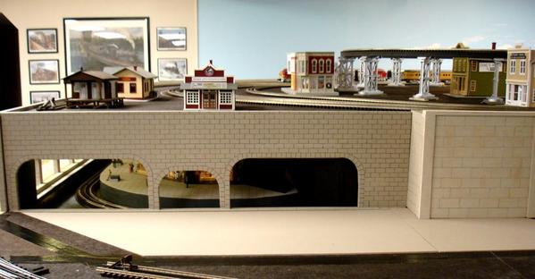
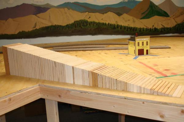
Alan – Remember, you were the one who got me started using the pink foam boards for rock walls and arches. In addition to the arches in front of the subway mall as I posted two days ago, I have used that method many times already.
One thing I really like about this method is being able to build the walls off site and then installing them and make them removable.
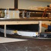
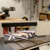
Here are more examples. (Click on the pictures to enlarge them)
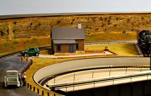
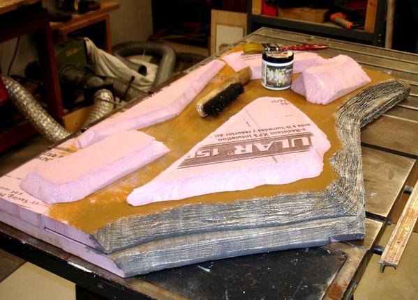
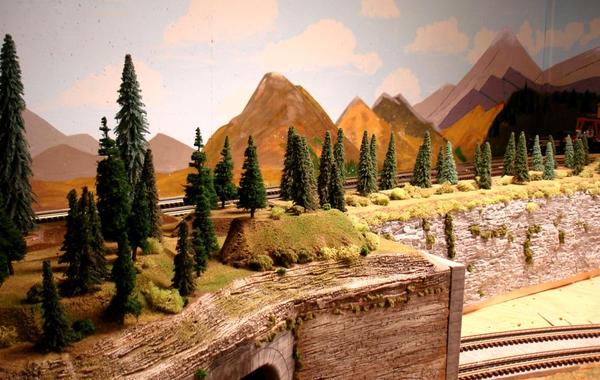
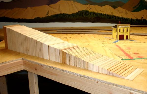
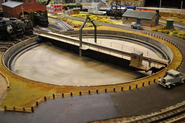
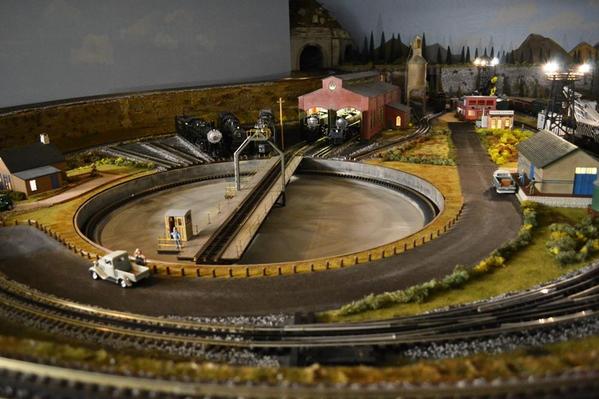
Early on, and as inspired by Patrick H.'s use of the pink foam for his marvelous rock walls, I used pink foam for the walls around the graded track on my layout, such as around the turntable area. I used the method Patrick described to prepare the foam: beat it with a crow bar, make horizontal cuts with a saw (I later used a hot knife), and scratch it with a steel brush.
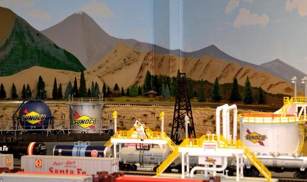
And around the refinery:
Then I started using the pink foam wonder other places, as Alan had suggested, such as here:
BEFORE
AFTER
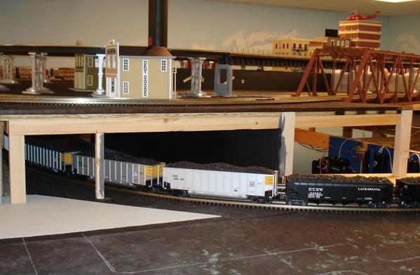
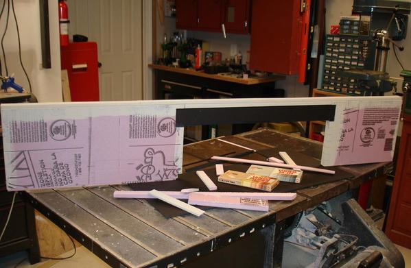
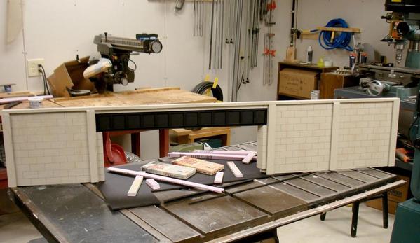
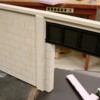
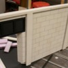
I made that wall, as well as all the others, off site. Here is a picture of the back of the wall:
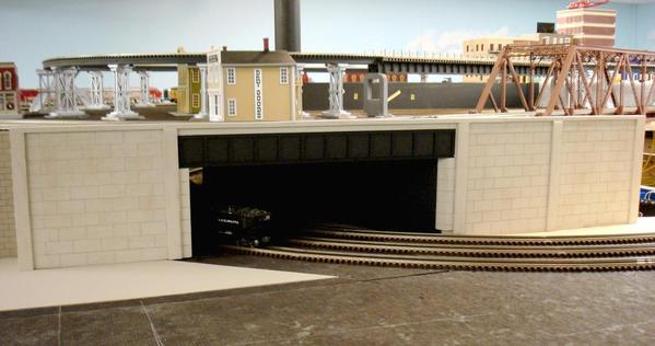
And the front:
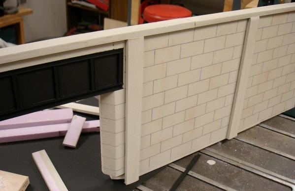
Detail: (The beam is 1/4" black foam board with plastic H-column at the bottom, horizontal, and plastic I-channels for the vertical braces)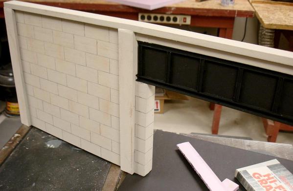
Detail:
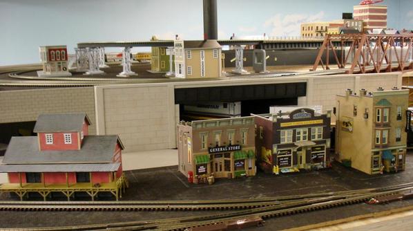
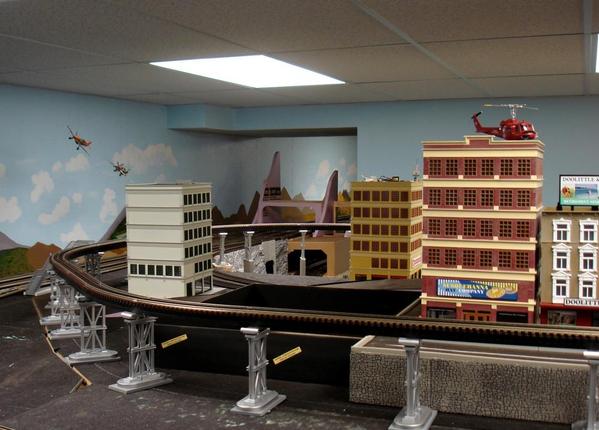
Some buildings in place, ready to add the road, ballast and other ground cover.
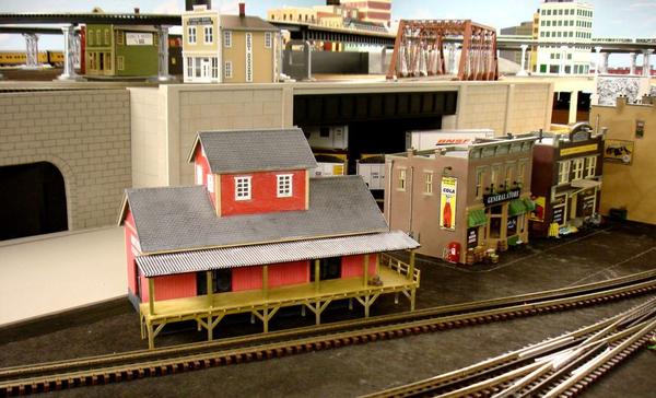
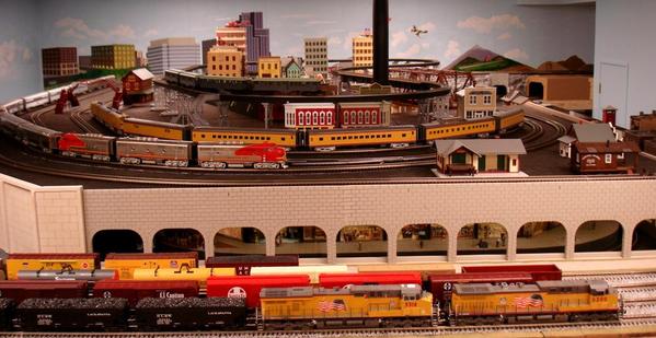
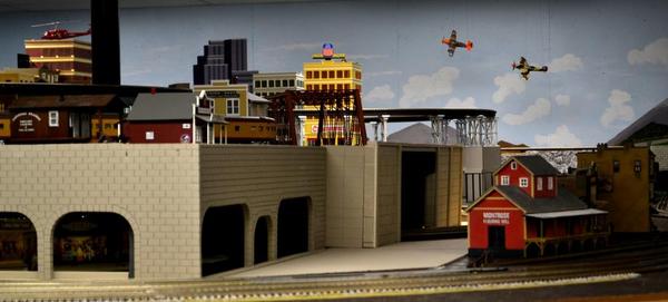
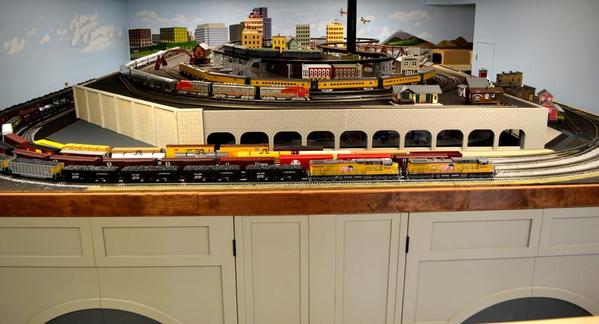
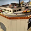
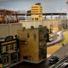
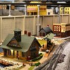
Another shot of the subway mall, from the side.
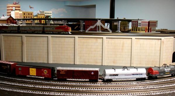
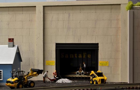
Another example of a simulated poured concrete wall, which also is easily removable and there is an access hatch in front of it.
Thank you for looking!
Alex
Attachments
How did you make the joint lines?
Alex, I'm always waiting for new posts of your progress, they are wonderful!
Leandro ...
Sorry I did not reply sooner, but I was at the “Mid-America 3-Railers” meet and at then at the wonderful picnic for the group at Alan’s (leavingtracks) house this weekend.
Lou -
I use 1/2" thick pink insulation board for the walls that resemble cut rocks, as the ones with arches around the subway mall, and also for several tunnel portals. I use 1" thick for walls that resemble poured concrete walls.
I tried many different methods for cutting and 'scribing' the pink foam board, and have settled on mainly two methods. For straight cuts of the 1/2" thick board, I use an X-Acto No. 26 blade and a straight edge. For cutting the 1" thick board, I use my band saw. The 1" thick board can be cut with the knife as well, but it is a bit tricky to maintain the cut at right angle throughout; but it can be done.
For cutting curves I use a hot wire and a template made of 1/4" masonite, but plywood or any other hard material would work fine for the template.
After the foam is cut to size, I paint it with latex wall paint that I buy at Home Depot in sample-size containers (about 8 oz) for under $3, and they will mix any color you want. (The foam can't be sprayed because enamels will dissolve it.)
After the wall is painted, I use a pencil to scribe the rock and poured form lines. For rocks, I use a slightly blunt pencil; and for poured concrete forms a slightly sharper pencil. I make my rocks 1/2" x 1" (2' x 4' full scale), and the concrete forms 1" x 2" to simulate a 4' x 8' sheet of plywood as may be used in real.
The poured walls also have an upper ledge and vertical reinforcements that are strips of foam 1/4" to 1/2" thick and 1" wide. I glue these to the wall with hot melt glue.
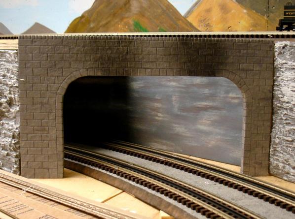
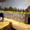
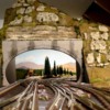
Here is an example of a tunnel entrance I am about ready to install. (click to enlarge)
Leandro -
Thank you - I'll continue to post as I progress.
Alex
PS. I forgot: For the tunnel portals - before painting them, I hit (softly) the wall surfaces with the ball end of a ball peen hammer.
Attachments
Alex,
Thanks for sharing! So many techniques to try when I get to that phase. Your layout is really coming along, look forward to seeing more in the future ![]()
-bruce
Alex, Your layout is really looking GREAT. Thank you for taking the time to post all the info and pictures. Keep ,e posted on your "POLE BUILDING SOLUTION" ![]()
a ball peen hammer! Never would have guessed that trick. Your portal looks terrific. I think I've got to try your method when I get to build my "real" layout.
Ron, the newbie.
Hi Alex beautiful work as always and really
great techniques.
THANKS, ALEX
Alex, you should write a book. Great work.
I agree with Lou. You should write a book. This thread is an incredible education. Keep 'em coming. Thanks.
Ron, the newbie.
Ah...this is a case where the student does better than the teacher!!![]() Alex, the portals look great.... I just finished cutting out another 8 feet of portals which are going on the south side of the city (you know where that is). I have still decided to leave out the blocks in this case because I want that poured concrete look. I will be scribing blocks with keystones over the openings and capping the tops of the walls then dry brushing vertical streaks on the flat "poured" surfaces.
Alex, the portals look great.... I just finished cutting out another 8 feet of portals which are going on the south side of the city (you know where that is). I have still decided to leave out the blocks in this case because I want that poured concrete look. I will be scribing blocks with keystones over the openings and capping the tops of the walls then dry brushing vertical streaks on the flat "poured" surfaces.
Keep those pictures coming!
Alan
Nice work with the foam. I like your walls and portals. I may be copying your techniques for a similar subterranean project I have coming up. Take that as a compliment as intended. Thanks for sharing.
Your post 4/20 10:03,
You used plastic "H" and "I" channels on the foam wall. Where do you purchase the plastic channels?
Enjoy each and every post, your layout looks fantastic. Thank you for your time to take pictures and posting them. They have provided much inspiration to all of us following your progress.
gsn1-
I buy the I, H and other structural shapes at the hobby shop and at train shows. My "LHS", 25 miles away (Mark Twain Hobby Center) normally has a good assortment and they discount it 10% or so. I also buy similar supplies from T and K Hobbies, and from Tower Hobbies.
As luck would have it, there was a vendor at the train show to which we went in Springfield, MO a couple of weeks ago (as part of the Mid-America 3-Railers meet activities) who was selling these and a lot more at 50%, 60% and 75% off! Evidently, the gentleman had bought the inventory of a store that had been hit by a tornado, and paid a minimal price for everything. I bought quite a bit of building supplies
BTW, the structural shapes that I use are the Plastruct ABS, dark grey in color, and are stiff; they are not the white, styrene variety, which is more flexible.
Hope this helps.
And thank you guys for your nice comments!
Alex
Alex, this is looking great, very nice foam work!
Alex, smart move on making the top hatch removable on your tunnel. I would imagine this will make track cleaning much easier in the future.
Bruce
Rich, Bruce -
Thanks! I try to make access hatches, etc. whenever possible, even if the need does not manifest itself initially. So far, every hatch has come in handy.
Even though I have a bit of it to do yet with portals and mountains, I decided to take a short break from the 'foam work' so I could work on the fascia.
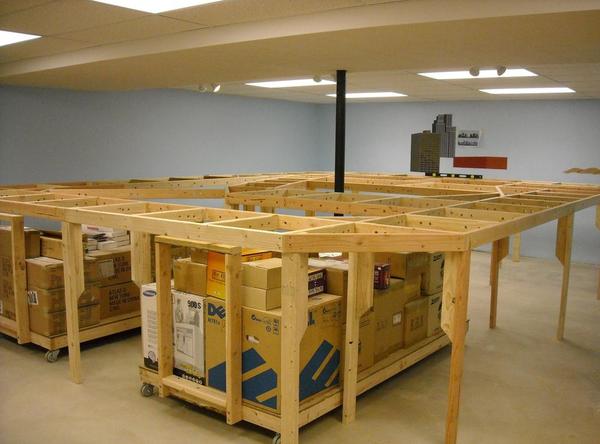
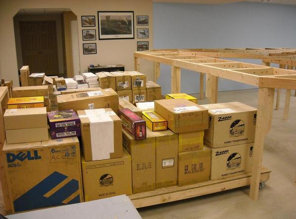
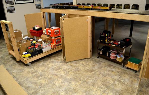
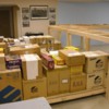
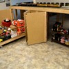
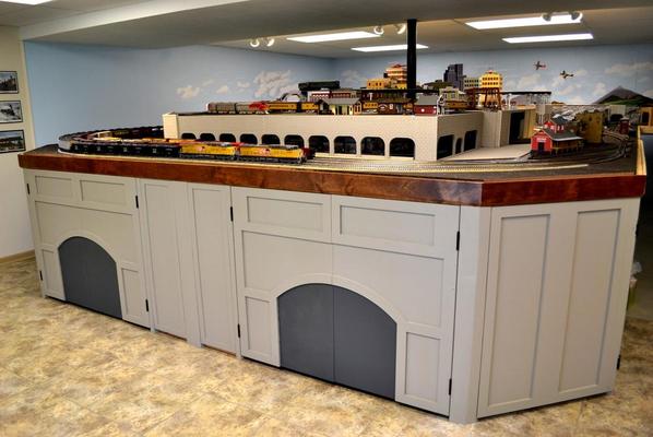
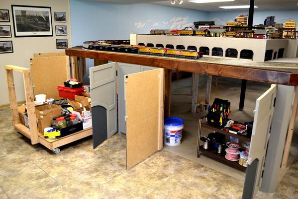
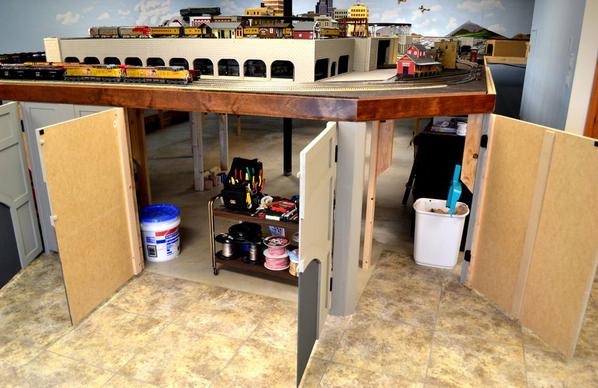
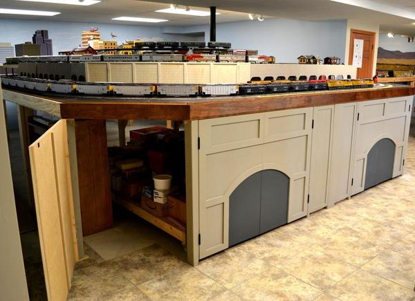
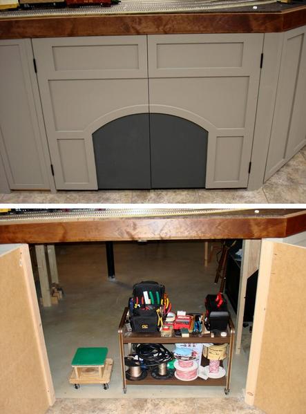
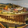
You may remember that I had built two carts to store and move the dywall and 2x4's around when I was finishing the basement (Aug 2010 through Jan 2011). I decided to keep them to store the train stuff under the layout, and they served me well. After a while I was able to disassemble one of the carts, and it became the base for the Subway Shopping Center as I described a few days ago.
Here is what the carts looked like about a year ago: (Click on the images to enlarge)
Carts under the layout . . .
And wheeled out for easy access to the supplies. . .
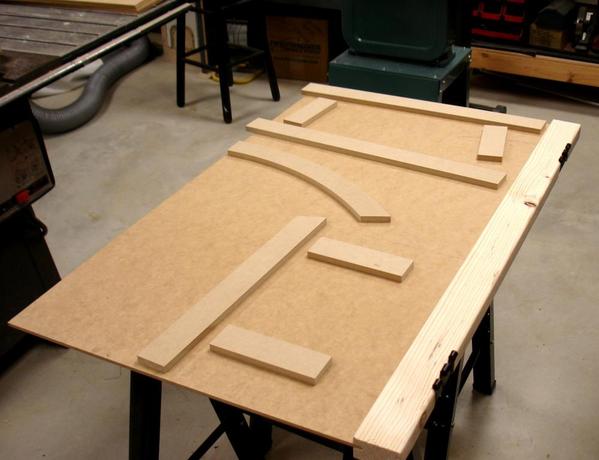
I have seen so many of you guys so wonderful things with MDF that I decided to give it a try for the fascia for the front of the East side of the layout.
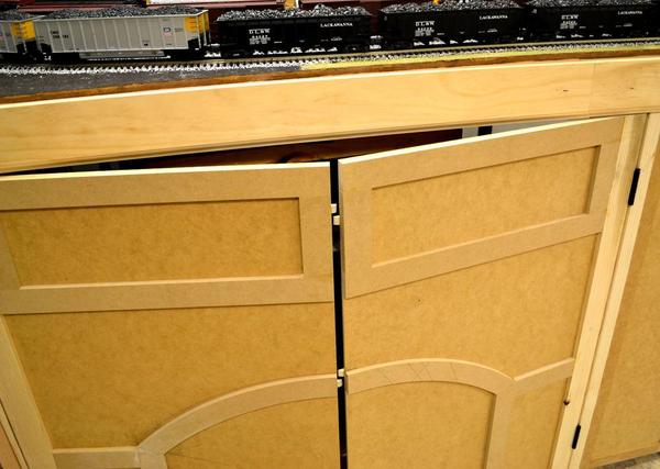
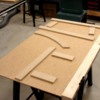
Starting with a 2' x 4' sheet of 1/4" thick MDF, a slotted 2x4, and some pieces cut out of 1/2" MDF . . .
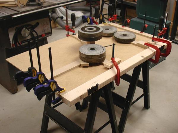
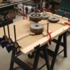
Add some glue and clamps . . .
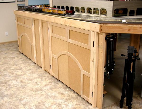
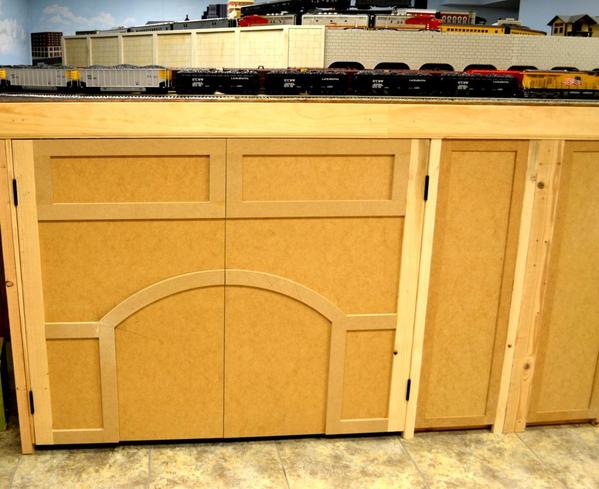
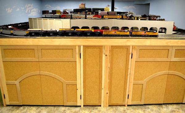
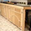
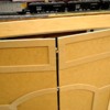
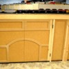
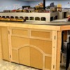
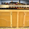
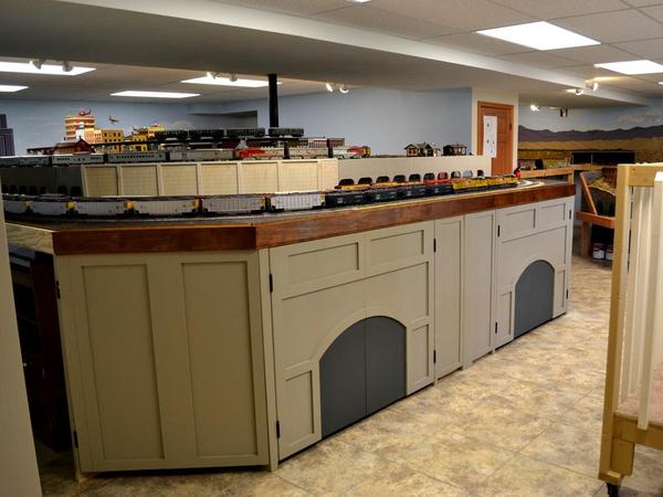
And voila! Some doors for the fascia. The hinges are of the loose-pin type, so it is easy to remove the doors if necessary.
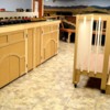
And they open up easily as well, for access to supplies and to pull the remianing cart out.
The doors interlock with small home-made tabs, and I used magnetic latches to keep them shut. I will be painting the front in a couple of days.
(What appears to be a cage in front of the layout is one of several viewing platforms.)
I will make two more doors for the angled corners, but the rest of the layout will have curtains around it.
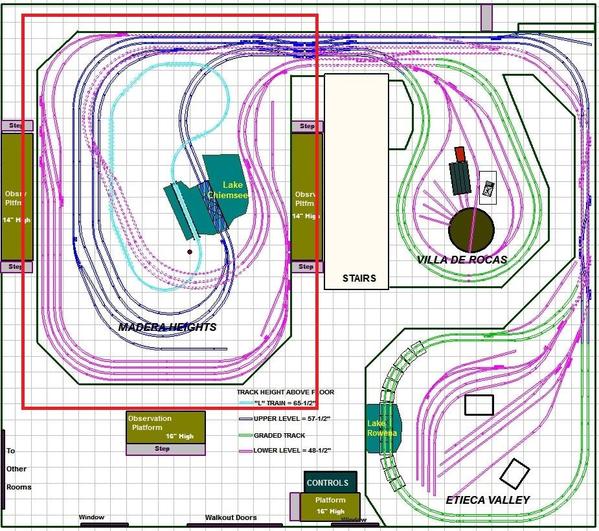
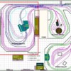
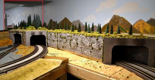
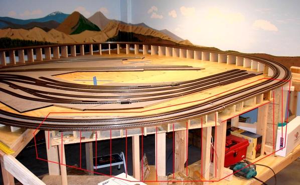
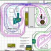
Next, I have a few new pictures to share with you that I just took of the area denoted by the red rectangle shown below.
Thank you for looking!
Alex
Attachments
Nice job on the doors! I have become a huge fan of MDF as of late.
Hi Alex that look's awesome what a professional job
I love it.That's all I use is MDF and masonite on my layout
THANKS, Alex
Alex...I just saw your posts above on the door....WOW....so this is what you were telling me about when you were here a couple weekends ago! Very nice work for sure....boy am I envious with you having that great workshop a few feet away from the layout area....really comes in handy for a talented guy like you! The doors look wonderful...makes me feel I am looking at roundhouse doors..![]()
Alan
Alex - Everything you do looks FANTASTIC! I always look forward to your updates
Beautiful work Alex. Your layout is an inspiration to all of us "wannabee" high rail modelers like myself.
My first thought when I saw the doors was that they resembled a "Tunnel Portal". They look great as they are, but did the thought ever cross your mind to finish them to look like a stone portal. With your talents I think they would be a real conversation piece finished that way.
REV
Alan, Louis
Thank you for your nice comments – very much appreciated.
REV,
You may not believe this, but I was ready to post this, and when I opened the thread to do so, I read your nice comment and suggestion.
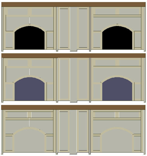
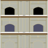
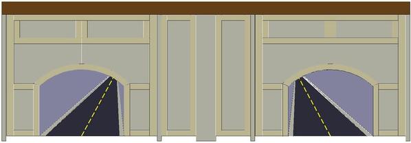
Yes, I indeed had portals in mind. The question now is one of colors if I do want the arches to resemble tunnel portals. I sketched the image, below, to solicit opinions, and since colors are simply a question of taste, there can be no absolute correct or incorrect answers – just honest opinions.
“A Question Of Colors”
(In the image I colored the raised features of the doors a different color so they would show up better, but when I paint the doors, all will be the same sandy-beige color, with a fine textured finish that resembles sand.)
What color would you paint the area under the arches? Flat black, dark grey, or the same as the rest of the doors? (Click to enlarge)
The top two may better represent tunnel portals, and the third more or less just doors, as perhaps for a roundhouse, as Alan suggested.
Thank you for looking (and contributing!)
Alex
Attachments
They look pretty good as is. I thought they were already finished. I would go with a concrete gray. I liked Floquil Reefer Gray for a richer gray base on a recent project that had cut stone details, then weather it down with chalks for your deal I think. Just a bit, because you have so much area that you want to give it texture, but that's enough. The concrete and aged concrete are too yellow. Doesn't work for me.
I have a similar subterranean station project coming up. I thank you for your blazing the trail. Great to see you having fun.
I guess it's a case of "great minds think alike", or some sort of "carma" I guess.
I kinda like the black, or possibly some darker shade of grey, that would more resemble the inside of the tunnel. I would also add some angled raised pieces above the portal arch, that would sort of "fan" out, further adding to the "stone arch" effect.
My first thought when looking at the design was that the portals were actually highway tunnels rather then train tunnels. Either way, I would add either tracks or a center dividing line starting at the bottom and "fading" out as if to create a sort of perception of depth inside the tunnel, as the line, or tracks appeared to get further away. It would be pretty easy to just paint over the lines if the effect didn't look right.
Whatever you decide Alex, it's going to look great.
REV
William, Rom -
I will start with a dak grey; the same paint I used for the edge of the raised floor of the shopping center (see below) and see how that works out.
REV,
"...I would add either tracks or a center dividing line starting at the bottom and 'fading' out as if to create a sort of perception of depth inside the tunnel..."
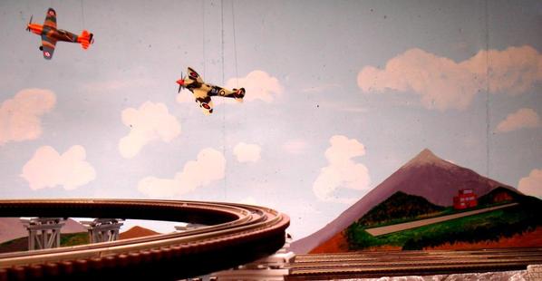
Now, that is a cool idea. I'll sketch it first and see how well I may be able to create that perspective. I have been able to paint the buidlings on the walls somewhat in perspective, and they look OK (at a distance). A couple of weeks ago or so, I also painted a runway on the wall to go along with two airplanes I had just hung from the ceiling. That worked OK as well - I think . . .
Thank you, guys!
Alex
Attachments
Alex......both look great to me. The runway sure gives the appearance of depth that I had in mind. I'm sure you'll have no problem with the perspective issue. As I said, even if you don't like the look, it will be easy enough fix.
REV
I should have the doors done in a day or so, and will post some pictures for your critique.
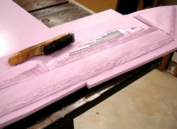
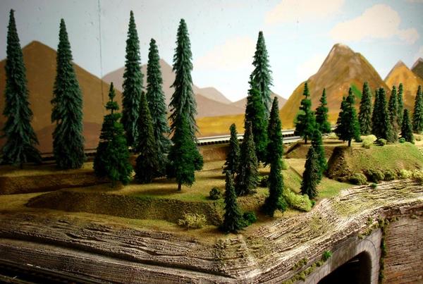
In the meantime, I more or less finished the section that I started with my post of April 29, above. I will add a few more trees, but you should get the idea.
The stiff wire brush does a nice job on the foam, don't you agree?
Oh, and I will also add a few deer in this 'forest'
I will have a few more pictures of the area - soon.
Thanks for looking.
Alex
(Edited to add):
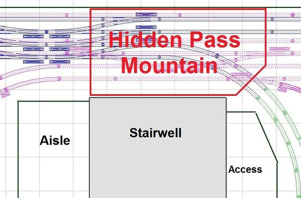
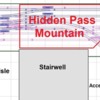
Oops! Forgot this picture. It shows where the Hidden Pass Mountain will be located (red line) behind the stairwell. It will have two tunnel entrances on the west side (this side) and a wide tunnel entrance (four tracks) on the east side. Will start working on this very soon.
Attachments
Very nice my friend!!! I'll bet that wire brush makes short work of putting in the "layers" of rock which creates a sedimentary effect.
Thanks,
Alan
Alex that's coming out so beautiful.
Great work your a true pro.
THANKS, ALEX![]()
Thank you, Alex!
Doors are now painted and the top stained and varnished. As you can see, the area under the arches is a darker grey, and we (Judy and I) are still wondering whether they would look better the lighter grey as the rest, but I am going to leave them as they are for a while, as they look OK.
As was mentioned before, another option is to paint something that would simulate depth, as perhaps a road into a tunnel (last picture, below). I can try this by painting a foam core board and cutting it to fit under the arches. However, the objective of the fascia is to hide the framework and not to get too fancy ![]()
But now I want to work on something else (the Hidden Pass Mountain) so the fascia for this section will stay as it is. Judy is looking for material to make the curtains for the rest of the layout.
And the doors still open
The texture is like sand paper. I added an anti-skid compound to the paint to achieve the finer texture, and I like how it turned out.
This may be something to try later on.
Thanks for looking!
Alex
Attachments
Alex it looks beautiful, I really like the dark color or even the last
picture. Alex paint it with railroad tracks and then paint a headlight
of a steam engine so it looks like a train is coming.
It can of course just stay the way it is its simply beautiful
Just professional work. I'm always looking forward to your
projects. Thanks for posting
Thanks,Alex
Hi Alex,
When you were installing the elevated sections of your track I saw that you were cutting support's graduated about 1/8" each 6". How did you attach the supports to the track supporting bed and to the decking on top of your benchwork? Did you predrill pilot holes from the top down? Thanks!!!
Alex,
Those are good suggestions and definitely things to be considered. Thanks!
Popsrr,
I just glued (Carpenter's Glue) the spacers to the 5/8" plywood top, and the QuietBrace to the spacers - at the same time. There was no need to add additional weight to keep everything in place and make the excess glue ooze out; the track and QB weight were sufficient. To add the glue, I just lifted the QB and track slightly, slid the spacers out, added the glue, and slid them back in place - one at a time.
However, I did not glue anything until AFTER I had the trestle bridge finished in case I had to make any adjustments to the track. But no adjustments were necessary. In the meantime, before gluing, the spacers just cooperated nicely and stayed in place ![]() .
.
That sure brings back memories . . .
March 26, 2011 - Spacers for one of the two grades.
April 16, 2011 - Track at trestle site on temporary supports.
July 17, 2011 - The trestle and grade at Etieca Valley complete (at top of picture), and the grade at Villa de Rocas ready to have its spacers glued.
Alex
Attachments
I would leave the painted doors as they are.
How steep was your grade in terms of %?
Lee,
Yes, the doors will stay as they are at least until I run out of things to do (![]() )
)
The layout has a dual mainline throughout, with Ø108 and Ø99 curves spaced 4.5" center to center. The grades are 2% for the inner track and slightly less for the outer.
Thx!
Alex
Alex....
The doors turned out fantastic!! I think they look fine just as they are....very nice job!
I will be getting in touch soon...
Alan
Very nice Alex. You continue to amaze me. Very nice quality work.
Alex, Thanks for your reply on the supports.
What size wood are you using for the supports?. Do you use the same width as the track support or have some relief? What are you allowing for width of the QB? Is the QBan 1" wider on each size? Thanks again Alex. Bill
Don, Alan -
Thank you for your kind words.
Popsrr,
Most of the supports were/are 3/4" plywood I had left over from other projects. Sort of an overkill, but a good place to use left overs, and they were stable. Others are 5/8" thick. I cut them the same width as the QB, about 8-1/4", as explained next.
The distance from outside tie outer end to inside tie inner end is 6-3/4” on my dual main. I cut the QB 1-1/2” over this, making it 8-1/4” wide. I angled the cuts 30° and that leaves about 7/16” from the tie ends to the QB edge on both sides.
A curved section:
And a straight:
Hope this helps you, and do let us know how you end up doing it.
Thx.
Alex
Attachments
Alex, Thanks for all the good info. Looking at your pictures is the "FABRIC" looking material sticking out past the tie a covering on the QB? What is your QG thickness? I never have seen it before. I assume Lowes or Menards would have it in saheets. Thanks for all your help.![]()
"FABRIC" looking material" ??
That is just the QB surface, which I painted grey for the straight section, and left it black (as is) for the curved section.
The QuietBrace (a Temple-Inland product) is 1/2" thick. I have only seen it at Home Depot, but others may carry it. It is a sound-deadening material for buildings. It comes in 4' x 8' sheets and sells for $8-$9 per sheet. I couldn't find Homasote, so I used QB, and I am happy with it. (Ask Alan/leavingtracks about it - he has been using it for years.)
Alex
ALEX, THANKS FOR ALL THE HELP.
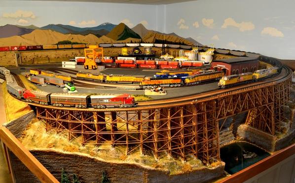
The Hidden Pass Junction Railroad has several tracks that join the two main sections of the railroad. These tracks are located behind the stairwell and hidden from the Control Center; hence the name of the railroad.
These hidden tracks can be seen and accessed from the service aisle (22 inches wide) and the lower level tracks are hidden from view for quite a span. The upper level tracks are readily visible, but I wanted to hide the short sections (about 4-ft) that are directly behind the stairwell, so I am building a mountain in this area.
The upper level tracks enter the mountain in two pairs from the west side, but all four are together on the east side and require a wide tunnel entrance. After considering several alternatives, I elected to use an eliptical-shape portal. NOTE: In the pictures below, North is down.
The Hidden Tracks - Upper and Lower Levels:
Mountain location (red line) as seen from the west side. The three portals shown are for the lower level tracks.
The pink foam shows the location of the mountain as seen from the west east side.
The east side wide portal is done! Eventually, you will no be able to see as much of the far side through the tunnel.
Here you can see the stairwell closet.
This side of the mountain will be connected with the other side at the top.
As seen from a passenger riding the "L" train.
Thanks for looking.
Alex
Attachments
WOW Alex that is just awesome work, I love the way that you built the mountain,
and the top above the tunnel portal is just beautiful. Alex you really should write
a how to book or make a video. You are a true professional, and every morning when
I first sign on I look for your updates.
Thanks for sharing, Alex![]()
Hey, Alex -
With as many pictures as I have been taking of the construction as I progress, your suggestion definitely is not out of the question. I would say that I post about 1 out of every 25 pictures I take, so there would be plenty to arrange in some sort of logical progress and to provide tips. But would there really be any interest?
Thx!
Alex
Finally finished the west portals and tied or connected the two halves of Hidden Pass Mountain. I like the west portals best.
West Portals
East Side
West Side
Thanks for looking.
Alex
Attachments
Alex It came out just beautiful.
Thanks for sharing.
Alex
Alex....
Got home to your e-mail with these pictures....your mountain and tunnels are very nice! I like how you went with the concrete poured type of portals and especially the 3-D appearance of the West portals. By the way, I will PM you either later tonight or tomorrow as far as what is coming up in June and the rest of the summer.
Alan
Thank you, Alex and Alan!
- - - - - - - - - - - - - - - - - - - - - - -
While I was waiting for the paint to dry on the mountain and tunnel portals (above posts), I started on Lake Chiemsee, which is the largest lake on the Hidden Pass Junction RR.
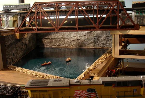
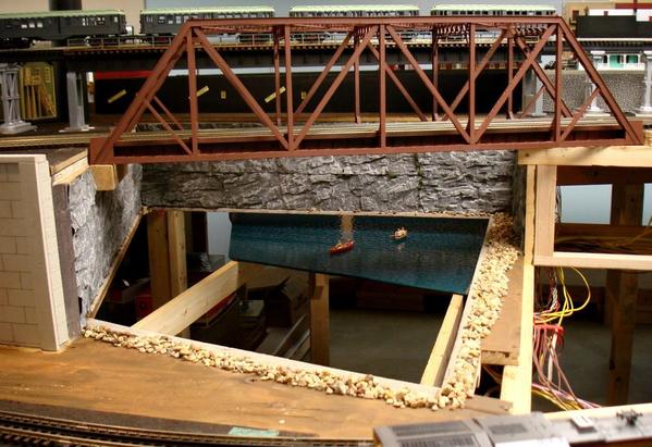
It is made of a piece of Aquatex glass (thank you Dennis Brennan) approximately 24” x 43” x 41” x 46” with just one right angle. I painted the bottom of the lake, the side of the glass with the most texture, Rust-Oleum Night Tide. I liked the Camouflage Green that Dennis and others have used for their harbor scenes, but since mine is a lake, I wanted a hint of blue, and the Rust-Oleum Night Tide fits the bill nicely.
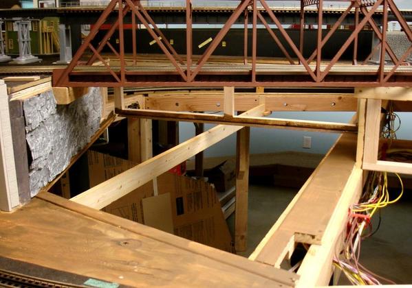
Due to the somewhat trapezoidal shape of the glass (except it has no parallel sides) it is easy to slide it back about two inches out of the three-sided grooved frame, and lower it. I built two rails under the lake to rest the glass once it is slid out from its frame. The rails are about two inches lower than the glass.
[Click on pitures to enlarge]
Lake Chiemsee almost finished (not done with details around the lake)
Another view
Glass slid out of the frame to become an access hatch
The 48X-size giant pops up to do detail work.
Frame detail and rail. The grooves on the frame are 3/8 deep and 7/32 wide (glass is 5/32 thick)
View of the frame at the front side.
Little by little, I'll get it all done . . .
Thanks for looking
Alex
Attachments
Looks great. I really like Dennis Brennan's idea of using the aquatex glass to represent water, and I like the blue color you used more than the green color I've seen in other examples.
A suggestion for the details, to have some sort of small boat ramp to allow the canoes access to the lake. There could be a dirt road and a vehicle parked with a rack on top for the canoes, or even some people waiting and setting up a picnic.
trestrainfan -
Yes, I like this color too. And those are good suggestions for details around the lake. I have some Scenic Accents that I have used on my other lake, and will see if I can work similar details on this one, as well as what you suggested.
Thanks!
Alex
Added a few more "openings" on the East side. (Click on pictures to enlarge.)
Made this timber portal out of left over pieces from the trestle.
Steel H-Column reinforced 'hole in the wall' serves as observation point for O-Gauge operator, and as access for the railroad maintenance crew.
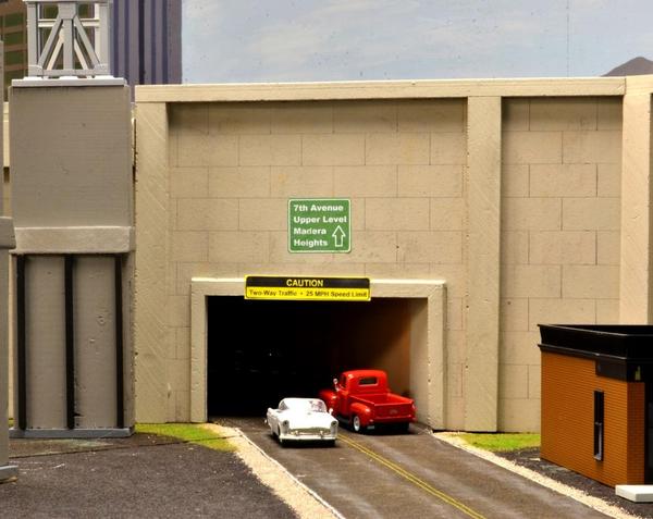
Road tunnel leading up to second level. Idea 'borrowed' from Alex Malliae.
Thank you for looking!
Alex
Attachments
I love the tunnel portals!
Well done!
The use of the "water" as a "pop up access point" is fabulous!
Peter
Peter,
Interestingly, so far I have made eight tunnel portals (not counting the ones that consist of girders, beams and H-columns), and all are different! ![]() I plan to make a video of trains running through these portals, hopefully starting today.
I plan to make a video of trains running through these portals, hopefully starting today.
Yes, that access hatch (lake) has already come in handy a couple of times, and I suspect that it will be more so in the future.
Thank you for your nice comments!
Alex
Alex the tunnel portals look great and thanks for the nice comment
about the road tunnels. You also gave me so many idea's from your
layout. That's what makes this forum so great we all help each other.
Thanks very much, Alex
Alex,
"That's what makes this forum so great we all help each other."
Yes, I agree: Like minds working together towards a common goal ![]()
Here is a more recent picture of Lake Chiemsee - not quite done yet, but looking better.
Attachments
Fantastic as usual my Friend!!
Alan
Alex, great pics, but you have to see it to believe it. Thanks for inviting Rose and myself to see it in person. Well worth the extra miles going to St. Louis.
Al
Al,
Thank you - you are welcome anytime!
BTW, I am just about finished with the Lake Chiemsee expansion and resort area - will be posting pictures soon.
Thanks again.
Alex
Alex, GREAT WORK! You give me so many ideas, if I only use a small portion of them it will be a great benifit. You should do a how to video or book.
Thanks for keeping us posted.
Mike,
Thank you for your nice comments. I have been taking pictures of what I do all along, about 2500 so far, and may look into what it would take to edit them and add some text to create a book.
Speaking of which, here are some pictures - four new ones and six from a few days ago. (Click on image to enlarge.)
Thank you for looking!
Alex
Attachments
Alex looks great. superb work.
Thanks,Alex
Ah yes...that last picture makes me want to jump in to cool off....it was 108 here today!!
Fine job as usual Alex....
Alan
Rich, Alex, Alan -
Thanks!
Well, I almost made it. ![]()
Yesterday would have been the first day since I started the layout 17 months ago that I would have not done anything to the layout, excepting the days I was not home, of course. All I had done up to dinner time was to run trains! ![]()
But after dinner, I happened to glance at the last area that was not ‘finished’, and just had to do it. It was another hatch that remained as an empty hole, it took a couple of hours to finish, and now I can say that all the ‘Heavy Construction’ is done.
All the track, basic wiring to the track and to the turnouts, (and a few accessories), all horizontal surfaces, all retaining walls and all tunnel portals are done. At least round one, that is.
Now I can concentrate on ballasting the rest of the track, adding the rest of the buildings, roads and ‘grassy areas; completing the street and other lighting, the train signals, and wiring the rest of the control panel.
When that is done – another year perhaps – I’ll get started on computer control. ![]()
In the meantime, I’ll run some trains and take some videos.
Thanks for looking!
Alex
Alex, congratulations at reaching your 17 month checkpoint! Look forward to seeing all your updates.
Bruce
Thanks, Bruce!
I was planning on waiting until the 18th month, the year-and-a-half mark, to deem basic construction done, bit it came a litle sooner - probably because now I am retired!
Here are a series of pictures I took yesterday of the current completion of the layout. (25 pictures take a lot of room, so it would be just as easy to click on the first thumbnail, below, and advance from picture to picture.)
Next will be a video of a ride along the entire layout one time.
Thanks for looking.
Alex
Attachments
Looking mighty fine Alex! I have enjoyed following the progress.
Steve A.
Impressive work Alex, especially the trestle span over land and water and all the different tunnel portals. Much to be proud of.
Alex....a beautiful set of pictures of a world class layout!!
Alan
How did I miss all this?? Amazing work sir!
...
I was planning on waiting until the 18th month, the year-and-a-half mark, to deem basic construction done, bit it came a litle sooner - probably because now I am retired!
...
Congratulations, Alex, on reaching this major milestone! I can't think of a better way to spend time in one's retirement. I only hope I'm blessed with the same opportunity in those years.
I've got a HUGE project in the planning stages that I'll be soliciting feedback on shortly. And watching your progress here (among a few other forumites as well) has been nothing short of inspirational.
Many thanks for sharing your adventures in O-Gauge trains with us.
David
P.S. I think I recognized an Intermodal Crane from my forum sales earlier this year that made its way onto your masterpiece of a layout. Glad to see it being used!
Steve, Dewey, Alan, SaabsndTrain –
Thank you for your comments; and as always, they are very much appreciated indeed.
David,
Yes, that is the crane I bought from you and it was a perfect addition. The Intermodal yard is one of the areas I have not detailed at all, but I will do so soon. I will have the crane operational, and plan to do an automatic cycle where it travels back and forth and raises and lowers a container, but will not drop or pick up a container; at least not automatically.
Thanks to all –
And Happy Independence Day!
Alex
Thanks for looking!
Alex
Thanks for looking!
Alex
Incredible imagination and workmanship, Alex.
After viewing all 8 pages, I can say that you guys will never see any pictures of my layout....I would be embarrassed for you to see how little skill I have. Fortunately my 3 year old grandson won't care.
I love the tiered look and I hope to copy it as well as I can....once I get my room built in the attic. :-( It's just too hot to work up there this summer.
Attachments
Hi Alex such a beautiful video, I've been waiting for you to post a great video going
around your layout. That was a great ride, I watched it twice and will watch it again
tomorrow morning. Thanks very much, Alex![]()
![]()
Leandro, Bill Alex -
Thanks for your comments!
Bill - That is a great picture of your grandson - he is welcome to 'engineer' my trains anytime!
Alex - Funny thing is that immediately after I posted the video and watched it on YouTube, I noticed several areas that I had intended to finish (scenery wise) before taking the video, but forgot. I had watched the video many times, but overlooked those details.
Sort of similar to proofreading what we write; we can read over our own mistakes time and again and not detect them until we 'publish' the piece. Oh well, it took me only a day to finish those areas, so they will be ready for the next video, on which I am working right now.
THANKS!
Alex
Somewhere in this thread someone mentioned oiling a switch motor with light oil. I don't think that is a good idea. The only thing I can recommend for lubing stuff is 5W-20/30 motor oil It will never dry out and become gummy like most other lubes do. 3 in 1 oil, most greases, Lionel Lube, etc., all dry out and become hard or gummy.
Alex, fabulous workmanship on that layout. Loved the tour! The INSIDES of those tunnels are neater than my office!!! ![]() Seriously... I don't think I've seen the inside/underneath of a layout look so neat. It's gotta be a joy to work on if you ever need to debug anything. Definitely an inspiration for us all.
Seriously... I don't think I've seen the inside/underneath of a layout look so neat. It's gotta be a joy to work on if you ever need to debug anything. Definitely an inspiration for us all.
Thanks again for sharing your talents!!!
David
David,
Thank you!
I added black foam core board to some of the tunnel insides if visible from the viewing areas so they wouldn’t look bad for pictures. I attempted to paint a couple to resemble a rock interior, but really did not spend a lot of time on those. Eventually, I plan to install Heiki rock foil that I have left over inside some of the more visible tunnels.
Other than that, the video shows part of the the 2x4 main frame and assorted 1x2,1x4, and 2x2 upper level support frame. The area under the layout is clear except for a couple of rows of boxes along a corner under Etieca Valley, so working under the layout as for wiring is very easy. Also, the lower level is 4-ft high, so the clearance from the floor to the bottom of the 2x4s is around 44 inches, and this helps a lot also.
Early on I made a small dolly/scooter to sit on and scoot around under the layout. I made its height such that I have about an inch or two clearance between my head and the bottom of the 2x4s. The picture below (click to enlarge) shows the scooter and service cart, and where I stored them.
The comments, suggestions, ideas, and solutions to problems I read from the forumites most definitely are an inspiration to me!
THX!
Alex
Attachments
Alex, I was watching Eric Siegel's latest video blog and found what may be the problem you had with your Legacy Signal at that tunnel entrance. I cant find the post you started on it for some reason, maybe you have already solved the problem, but I thought you would want to take a look.
Starts 9 minutes into the video
Great video Alex. Thanks for posting.Still laying my track on my layout but your posts and others have given me guidance. The 50 + sheets of quiet brace have worked out very well.
Dale H
Zett,
Yes, I solved it pretty much the same way as Eric showed. I ran a wire from the actual ground connection of the outlet, up to the layout and under the upper level for the length of track that was giving me problems; about 6-feet or so. I used insulated wire and it works fine.
A minor point about Eric's video: He said that the ground on the outlet runs to a ground rod. Actually, the ground terminal wire (usually bare wire) and the common terminal wire (white) of the outlet both run to the same bus bar in the electrical or circuit breaker panel, and on to ground. When I finished the basement – from scratch – (the 6th I have done and hopefully last one) I did all the wiring myself, as everything else, so I know that the outlets are properly wired.
To avoid removing the outlet plate and working on the outlet itself, some suggested using a three prong plug to connect the ground wire (ground plane is a misnomer) to ground. Others suggested the method Eric used; i.e., using the screw that holds the outlet plate as the conenction point since it screws into the outlet frame, which should be at ground potential. This last method is probably the best for anyone to use.
Dale,
I am glad your layout is coming along well and that you are doing well yourself! Looking for your progress reports too!
Thanks for the nice comments.
Alex
I think you may need these?
MTH Catenary Hardware Pack
And I think you need these...
RealTrax - MTH 8-Piece Catenary System
Hi, Jake!
As F.Smaritano mentioned, the ovehead electric cable/wire system used to supply electricity to the trains is called a Catenary. There have been several threads posted by contributors who have these on their layouts.
I would suggest you start a thread on the "3-rail, O-27 . . ." forum section and entitled it "Your experience using a catenary system as the actual power source." Ask how easy or difficult it is to install one. I am sure that you will see many good answers.
Here is one on the subject:
https://ogrforum.ogaugerr.com/d...400#3400749726000400
Good luck, and thank you for your P.S. ![]()
Alex
P.S. FWIW, the word catenary actually means the curve described by a cord when suspended from its ends.
Jake,
Regarding catenary hardware - If you want to know what is available 'new' and what is needed, you may call Jason /Jason's Train Shop at (814) 495-4329 and ask him those questions. You can tell him Alex suggested that you call him ![]() .
.
Also, I see that you posted your questions on another already on-going thread; this may or may not work. Don't be bashful about asking until you get the answers that you need.
Good luck!
Alex.
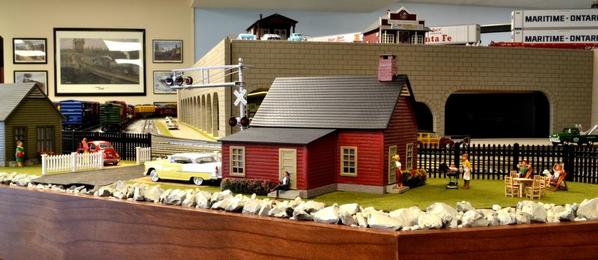
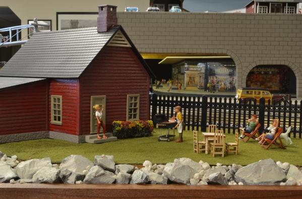
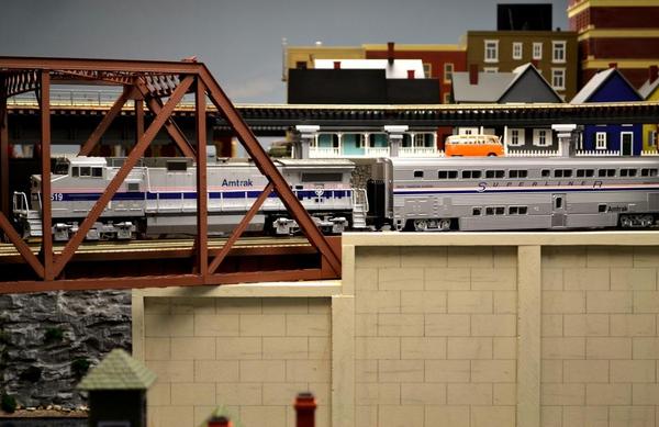
Friends, it has been a while since I updated my layout construction thread, but that does not mean I have not been working on it! I have been making progress on some scenery details to three corners of one portion of the layout. I also have a new Amtrak passenger train.
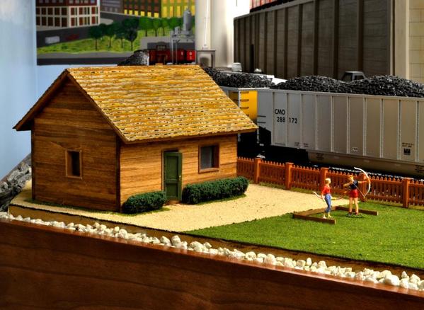
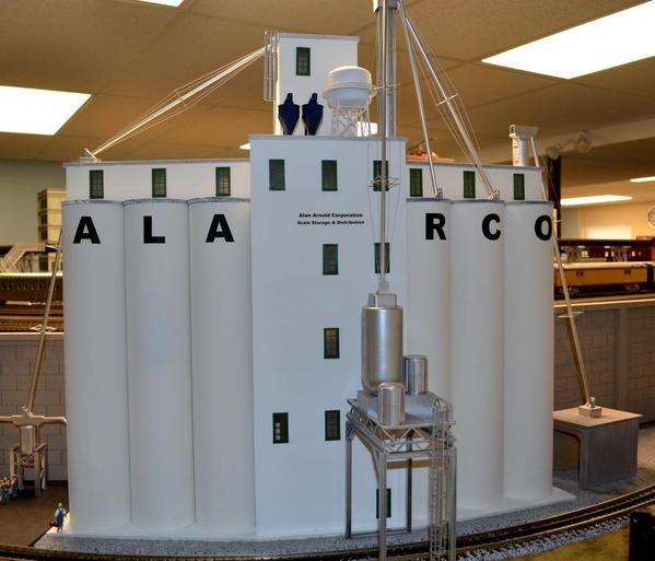
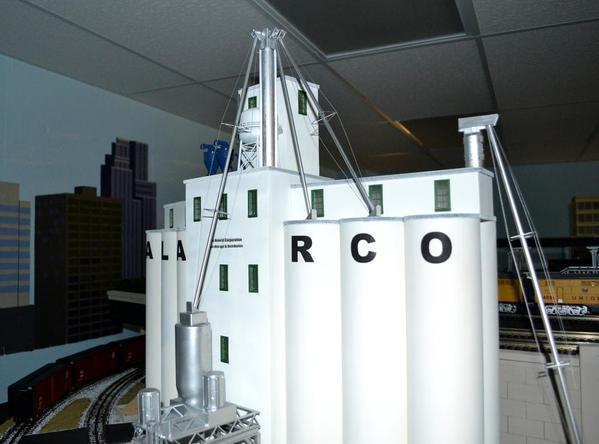
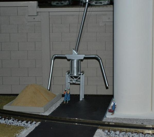
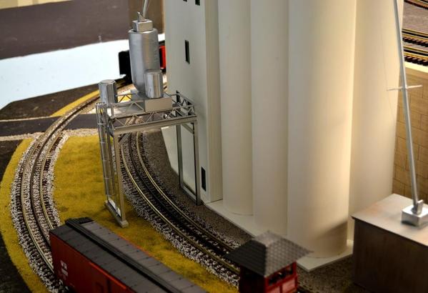
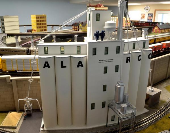
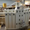
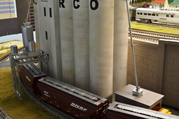
The NW corner has a couple of houses next to a railroad grade crossing, the NE corners now has an archery range, and the SE corner is the venue for the superb ALARCO granary, which as many of you have already seen, I covered in it own thread.
Here are some pictures - (click to enlarge or click on the small pictures below for a really nice black background - new feature of the forum?))
Thank you for looking!
Alex
Attachments
Alex,
Your layout is beautifully done. Please post more pictures and a track plan. Keep up the good work.
Lou
Absolutely amazing photos. The scenery looks fantastic, keep the photos coming.
Alex....
I am becoming ashamed of my layout!!! Your pictures of the progress are amazing....just beautiful. By the way, got the piping you made for me installed last night. I will post some pictures soon.
Thanks,
Alan
Alex such amazing beautiful scene's, and craftsmanship
I enjoy your photo's very much. Thanks, Alex
Lou, Chris, Alan, and Alex -
Thank you for your nice comments!
Lou, the track plan for my Hidden Pass Junction RR has proven to be more enjoyable than I had envisioned, and even I sometimes lose track of where the trains will be coming from and have to look at the diagram or at the control panel. The stairwell, which I thought was a big impediment, turned out to be a nice division between the two sections of the layout.
The Hidden Pass Mountain, as you can see below, is behind the stairwell, and is where the junction occurs for both the upper and lower levels of the two sides of the layout. Another feature that is not readily seen is that each of the two mains has a double reversing loop.
I have most of the scenery done for the lower level of Madera Heights, and one block section of buildings on its upper level is also done. Now I am ready to start ballasting the second level of Madera Heights, after which I will start on Villa de Rocas and Etieca Valley. Following that, I will continue working on the controls until I have full computer control. I have enough fun to last me for a good while.
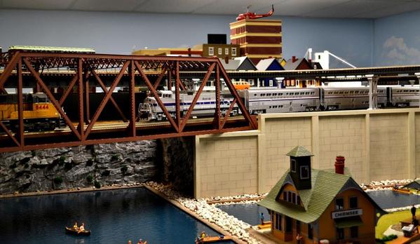
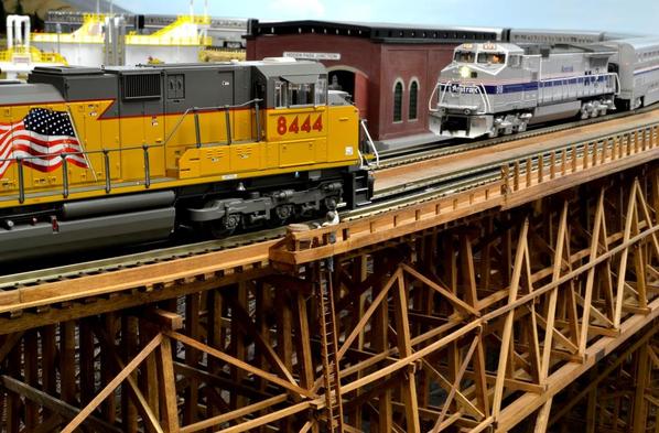
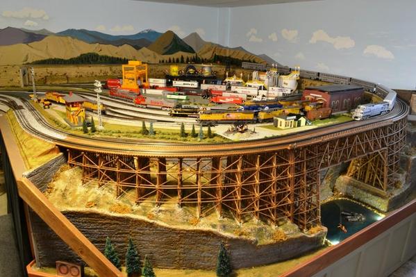
Here are a few pictures of trains crossiing the Judy Jane Trestle.
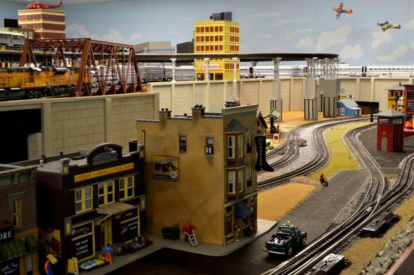
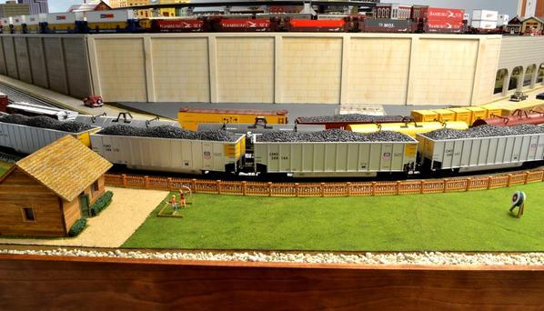
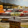
And the yard just outside the subway shopping center.
Thank you for looking!
Alex
Attachments
Thanks Alex, it is as beautiful as can be, and I am sure that it gives you many hours of operating enjoyment.
Lou
Excellent Alex,
Looks great!
Alex once again I must say your layout is pristine
JUST BEAUTIFUL
ALEX
Awefully quiet lately. You still recovering from the visit?![]()
Alex,
I have 2 Questions, which I am hoping you can provide some fairly detailed answers to. ![]()
#1) What type of wood (dimensions of wood) did you use for the foundations/ piers for your transition ramp from the upper to lower level? Part II of that question is; how did you figure/ find the measurements you needed to determine your angle of elevation from the Starting Pier to Ending Pier? And Part III; how did you cut the angle on each pier?
#2) Did you build your curved trestle from scratch? If so, what type of materials were used to build it? I'm asking this question because, for my layout I would like to build a 4 foot long trestle with a straight section of 32 inches, and the remaining 16 inches having a curve that would line up with an O-72 radius.
James,
I am sorry I waited this long to answer your questions, and wonder if I am too late. I wrote an article for OGR Magazine, which appeared in Run 256 (April/May 2012). In those nine pages I described most of the details of construction. And yes, I designed it and built it from scratch.
And thank you all for your comments!
Alex
If you do not have the magazine or otherwise have any questions, please email me - I'll be glad to help you out any way I can.
Thx!
Alex
I have not updated my layout is this forum for a while, but that does not mean that I have not been working on it.
Here is a video to bring you up-to-date (same as posted in the 3-rail 0-27 . . . forum)
Enjoy!
Alex
Hello Alex. I recall that you chose to use QuietBrace for sub-roadbed noise reduction. How's that working out for you?
Alex,
Your layout is amazing. I really love your trestle bridge.
Beautiful layout. The word has been used before but you are an amazing talent. I just marvel at your creations.
My wife and I recently were guests at Alex and Judy's. His layout is beautiful and runs perfectly. The quiet brace has worked as planned and greatly reduces the noise level.
Alan
Alex WOW the layout is looking WONDERFUL!! i REALLY liked therBNSF POWER and coal train. Very very nice indeed. Thanks for shating with us.
Boy Alex,
I cant get over how well your layout is coming out. Just superb and something to really admire. I may have mentioned this before but I just love when the engine comes out of the tunnel and down the long sweeping S grade. Fantastic layout from a fantastic person.![]()
Alex,
I watched the video last night on my big TV. Really looks great.
-Ted
Stellar layout.The video was fun to watch too!
WONDERFUL! You make it all appear to be so easy....but I think we all know it's FAR from easy. You're doing a fantastic job and thanks for dedicating so much time to posting your pix and comments on the forum.
Be safe, be well.
I have failed to take the time to post recent pictures of the Hidden Pass Junction RR, so here are a few of the areas I have modified more recently - thumbnails below. (I've been working on other train-related projects other than on my layout - but these have been extremely enjoyable as well.)
I will be posting a new video in a few days, and plan to have close ups of the more interesting areas.
Thank you for your interest!
Alex
Alex
Attachments
Great Pictures as always Alex. I really enjoyed visiting with you and Judy with my "friend" a few weeks ago.
Hope all is well and please keep the pictures coming.
Hi Alex,
You really got a lot of scenery work done, and it really looks beautiful. Very well done
thanks for sharing, and you know I'm looking forward to seeing a video!!!
Alex
Alex,
I was wondering. Are they designing an Engine that runs on Static Electricity at the John Galt Research Facility??
Ayn Rand is alive and well on your railroad LOL
Happy Railroading,
Ed
Amazing layout! Your scenery is looking great!
Roger,
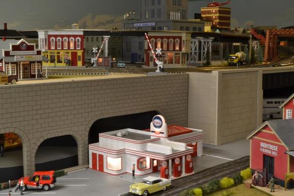
I was able to take a little time since you were here to work on two, rather neglected corners and install two operating accessories. The Esso Gas Station and adjacent parking lot, the Woodsman spot, and an unloading car site.
Alex,
It goes without saying, you are welcome anytime. I am counting the days to York and to visit you and see your layout then.
Ed,
Most definitely! As a matter of fact, in the rear of the building on the lower section rooftop, there is a Ultra High Speed Friction Drive Static Generator.![]()
Jim,
Thank you as well!
Alex
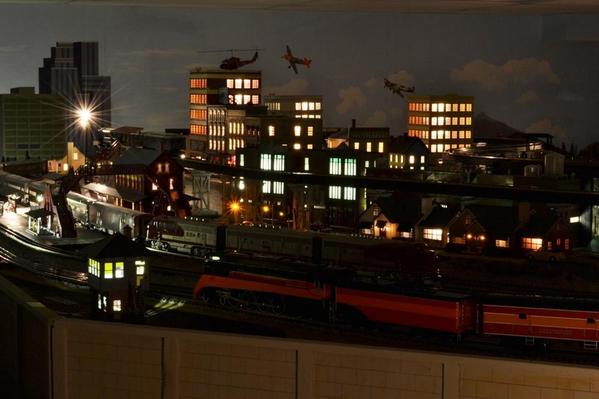
Really cool---love the night shots
Thx for posting
Joe S ![]()
Joe,
I appreciate your comments. Thx!
I will use this opportunity to post my latest video here in case anyone looks in this forum section for updates. The video shows recently improved areas. Please note that the video is HD, and shows very well in large TV's.
Thank you for watching!
Alex
Alex,
Really nothing to add that hasn't been already stated. An excellent layout! Wish I could bring my UP locos over and run them with your rolling stock. Well done...sir....well done!
Alex
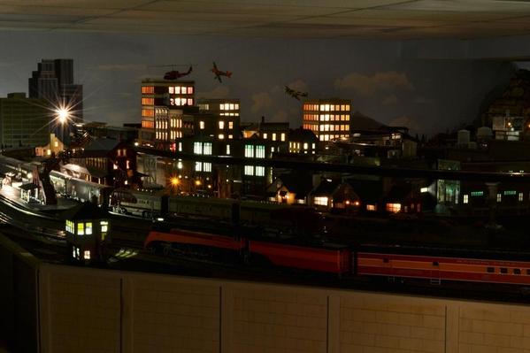
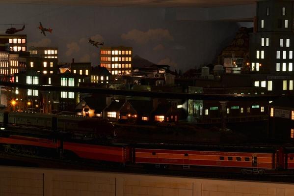
Your layout has really come a long ways since I saw your pop up access hatches. Your efforts have achieved a WONDERFUL LAYOUT. So many GREAT EXAMPLES of your detailed efforts are reafly sean all over the layout. You have already captured my full attention and admiration of your work BUT, The NIGHT PHOTOS are just absoluteY a WOW FACTOR!!! Congratulations Alex. Bill
Pat, Bill -
Thank you for your comments - very much appreciated.
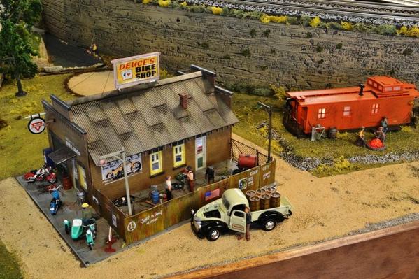
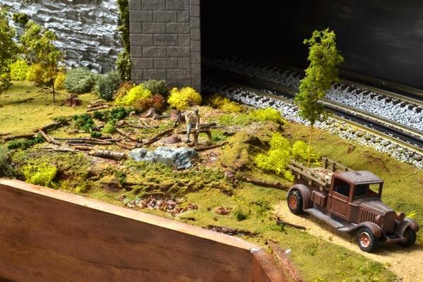
And one more picture, of a scene that I included in the video (above), and which scene I finished just prior to making the video. The Saw Mill -
It is operational, and the dump car is operational also. I will have push button switches on the edge of the layout for fans to operate the accessories. I have done the same at several other locations, and people really like them. (The red button is almost flush with the edging, below, and operates the Esso Gas Station.)
Thanks!
Alex
Attachments
Alex,
Amazing layout! I love your attention to detail and quality of work! Your model railroad is inspirational!
Marvelous layout Alex. How big is it?
Ken
Alex it just dawned on me that this is the layout I will be seeing Saturday, looking forward to it.
Ken
Hi Alex,
Beautiful scene's and expert work as always
Thanks, Alex
A.I., Ken, Alex -
Thank you!
I have a five areas yet to finish; i.e., they still have the raw QuietBrace as surface, and I will be working on them soon.
I am also trying to finish all the wiring. This means connect the remaining 23 turnouts (out of 57) to the control panel, because even though all are connected to the AIU's, I like to have both the AIU control and the toggle switches at the control panel.
I also need to wire the remaining 53 sensors for the turnouts. These are sensors for which I have a patent applied, and sense the true/actual position of the points without contact to the points. They do not in anyway use the switch machine or the control signal to the switch machine, are totally independent and accurately sense the points.
All in all, about 6000 feet of wire to go, to make the total around 14,000 feet.
And then computer control . . .
Ken:
As you will see in a couple of days, the layout room is 33' x 38' and the layout occupies about 80%, or 1000 Sq-Ft. Looking forward to your visit.
Alex
WOW... Nice job, keep up the good work and thanks for sharing!
Great work Alex! Its been great to watch your progress.
Very inspirational Alex....makes me want to put in more hours on our layout.
What caught my eye this morning, is the in depth and detail, in the street, landscaping.
Amazing ! (pic #6)
Alex, You have explained the viaduct, construction, but I have 1 question,??
What are the Grey, Supports, and are they approx 6" high !!!
Really , like both yours and Alan's girder/viaduct construction--- I keep making notes
THANKS !
JD, Louis, LOS, RGP -
Thank you for your comments!
Terry,
I believe that what you are referring to are the MTH Railking Elevated Subway Trestle Set (40-1047, 40-1157). I had to add a 1/4" base at the bottom in addition to the 3/4"-high stringers I had under the track to achieve the proper height to clear the tallest Intermodal car I have, by just 3/16".
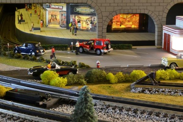
Here a few more pictures of the Subway Shopping area.
Thank you all!
Alex
Attachments
I have failed to take the time to post recent pictures of the Hidden Pass Junction RR, so here are a few of the areas I have modified more recently - thumbnails below. (I've been working on other train-related projects other than on my layout - but these have been extremely enjoyable as well.)
I will be posting a new video in a few days, and plan to have close ups of the more interesting areas.
Thank you for your interest!
Alex
Alex, good afternoon!
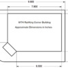
I need a big favor from you, I'm riding my town and need to know the size of MTH Corner Building but without the sidewalk (gray) of your photo DSC_1989 A07 med.
Thank you,
Leandro ...
Leandro,
Is this what you want: (Click on picture for full size)
Let me know if you need any other dimensions.
Alex
Attachments
Alex,
It's been a pleasure following this thread from the beginning. You have done so much in a short time. I look forward to your updates. Keep up the great work.
Andy
Marshel
Alex is a real craftsman and as you can see has done a WONDERFUL JOB on his layout details.
Andy, Marshel, Bill -
I haven't looked at my own (this) thread in a while, and missed your nice comments.
Thank you!
I am working on finishing the scenery in a few areas, but primarily I have been concentrating on automating the operating accessories. I am making the accessories such that at the single push of a switch, the accessory will run for a complete cycle. The pushbutton switches are located on the edge of the layout, and also are connected in parallel with switches on the main control panel.
Visitors can easily run the accessories and I don’t have to worry about the operation being stopped in the middle of a log or drum load, or a dump car stopped before it returns to the ’home’ position. A few accessories, such as the MTH Filling Station, will run automatically once the cycle is started with the switch, but most other accessories require that a switch be held to complete the operation.
Now I can detect and keep track of drums available to load, cut lumber ‘in-stock’ for the Lionel Sawmill to run, dump car in position before it can dump and the dump cycle complete, and so on.
Alex
Alex, great to talk with you this weekend. Sounds like we need to come up there and do an "inspection" of all of these new electronics. I have seen the drum you fixed up and now I would really like to see your sawmill in action.
Hope you and Judy have a great week.
Alex, Hi I have recently finished reading about your layout over a month long period. Your work is fantastic! Before reading your thread I could not begin to think of such a fabulous layout, although the reason I started to read it was the fact that I am in the early stages of planning my own new layout.
In my first thoughts of a new layout I was planning to go with Atlas track, but somewhere along the line I heard that there was a problem with electrical continuity when using the Atlas track. I read the post where you showed how you drilled and then screwed your power supply right to the rail. I'm guessing that method completely removed any such electrical problems. Please advise If my assumptions are incorrect.
Following my doubt with the Atlas track I was pretty sure I would be using Ross switches with Gargraves track, but then, lo and behold, you ran into a problem with your Ross switches, but not the Atlas ones. I don't recall seeing how you overcame your problems with the ross switches, or whether or not you did at all.
The layout I am planning will not be on as grand a scale as you have there, more likely it will be about a third of the size or less; just the same I would like your input on these items before I go and purchase a bunch of track and switches.
By the way thanks for a bunch of good reading, I hope that I can retain enough of your lessons to help with my new endeavor when it finally gets off the ground.
Rich
Thanks for the feedback Alex, it will sure come in handy, and once again that is one fantastic layout you have created. Rich
Alex, great to talk with you this weekend. Sounds like we need to come up there and do an "inspection" of all of these new electronics. I have seen the drum you fixed up and now I would really like to see your sawmill in action.
Hope you and Judy have a great week.
Roger,
I had meant to let you know that in a couple of days I will post (YouTube) a short video of the sawmill in operation together with the preceding operations.
Rich -
You are very welcome.
Alex
Alex, what can I say but WOW!! Love the detail, love the trains.
One of the very best layouts I have seen. It makes me want to
work on my layout. Again Alex it is GREAT Layout. Thanks
![]()
... It makes me want to work on my layout...![]()
That is a very nice compliment, and I hope you do!
Thank you!
Alex
Thanks Alex, looking forward to seeing this accessory in action.
Alex, I cant wait to see your new video. That must be really frusturating with Youtube, I hope that you dont have to redo the entire video.
What camera are you using? Your June video was amazing. I cant wait to see what you have accomplished since.
Thank you Roger and Zett! I really appreciate your comments.
I just posted the video in the "Hi Raill O27 . . ." forum, here:
Believe it or not, that video (5th attempt) still is 'in process' according to YouTube!
Alex
Really cool video Alex, been watching since the beginning, great layout, can't wait for your next post always seem to get better.
Jack
Alex
Well Done IS the Shay Lionel, or MTh???
Steve
Nice job Alex , left message at other post also. !! Thanks for sharing
Great video Alex! Your continued progress has been fantastic!
Jack, Steve, Alex, Louis -
Thanks!
Steve, that is a Lionel TMCC 3-Truck Shay (6-11157), which I run with the Legacy remote.
Alex
Shortly after the first of the year (2014) I started adding a few structures, weathering, and ground cover for the Steam Park in the HPJ-RR, as well as weathering the grain elevators. I would like to share a few pictures of the results. The last picture - the track layout - shows where the grain elevators and the Steam Park are located.
Click on the pictures (or thumbnails, below) for clearer details.
Thank you for looking!
Alex
Attachments
As always, wonderful job Alex.
Wow, all looks fantastic! I think we should all move to the same neighborhood and just rotate what house to go to for dinner every night. We can start at Alex's house.
Hello to you and your wife. Thanks as always for your willingness to share your layout.
Buzz Lee
Fantastic layout.
Alex, Fantastic job. I really like the weathering.
VERY NICE Alex
Ken M
The layout looks great Alex. Really love that grain elevator, especially the way you got it to fit that curve.
Thank you all for your comments! Makes sharing a joy.
Zett,
Cooking is my wife's favorite hobby, so you are very welcome to dine with us!
Buzz,
Judy says hi as well.
Al,
I was apprehensive of weathering the turntable and mess it up, same concern I had with the grain elevators. But they turned out OK. See below - - -
Ken,
Will you be coming to the Great Train Expo in St Charles next weekend? If you do, make sure to stop by.
Elliot,
Oh, yes - Alan (leavingtracks) made that for me. I gave him the dimensions and a sketch of the space I had available, he custom made it, and it fit perfectly! I just added the piping and the weathering - very cautiously.
Thanks to all again.
Alex
A couple more picture of the Millhouse River Studio turntable under different lighting.
Attachments
Looks great Alex............ ALOT of new details. Really nice job buddy.
Alex - simply fantastic! I wish I had your skill.
Hi Alex,
The layout looks fabulous, awesome scenery and superb detail !!!!!
Say hello too Judy
Thanks,
Alex
Alex,
It's always a pleasure to see your updates. Great work.
Andy
Patrick - Yes; going around the second time allows for more details as I am not in that great of a hurry. (Still trying to catch up with you, though.)
Sean - Oh, I don't know about skills, but old age does provide experience.
Alex - I will.
Andy - I'm always glad to share.
Thanks a lot for you nice comments!
Alex
Alex...just caught this update... The layout looks fabulous!! Going over it several times like you have...and adding details has really turned it into a museum masterpiece. I like the weathering as it is not overdone...it looks perfect to me. That grain elevator is nice too!!![]()
By the way, when Alex says Judy's hobby is cooking...what he really means is Judy is a master chef...let me tell you...I know this from experience. The layout is nice but the cherry on top is Judy's cooking. When you are a guest at Alex and Judy's home, it is like being on the best vacation cruise![]()
![]() .
.
Alan
Wow Alex, looks great. Love all the new details and weathering....especially on the grain elevator and the TT pit. Excellent job.... OGR should do a feature in an upcoming DVD/Blu Ray for Great Layout Adventures ![]()
Alex hope to come to the show
Ken M
Looking great with the details Alex. Ive learned quite a lot from your thread. Thank you!!
LOS,
• The grain elevator and the turntable are among the most eye-catching elements on my layout; fortunately, the weathering did not change that, and perhaps made them even better.
• Good enough for Great Layout Adventures DVD? Well, I am not sure about that, but really do appreciate your compliment.
Ken,
I'll be looking for you.
Louis,
Details are slow to develop but lots of fun, and the end results 'usually' are rewarding.
Judging by the progress on your excellent layout, you will be doing your own detailing very soon.
Thanks to all!
Alex
First the "gushing" awesome..inspiring amazing..a worthy accomplishment since 2011...
you have set the bar quite high...(makes my layout look awful..which it is.but I have reasons) . such focus and single minded determination.a clear plan is a must...
.I am always second guessing my designs...(I built many Ho layouts that never got past track because of track changes, in search of the layout that would do it all..)
now I have MTH O scale..collecting for over 10 years..have DCS and only 5 steam and one diesel switcher..and about 40 rolling stock..cost has been a barrier..
which leads to my questions, please pardon if you have already answered, I have not perused every page on your posts,,,
What system are your running..?
Are all your engines and cars MTH?
is there any pictures of your system?
Also interested in your upcoming patented idea..
a few personal questions..
what was your estimated budget for this extravaganza? did you manage to stay with in it..did you start collecting before 2011 or is all this rolling stock and engines since 2011?
will you adopt me? lol
thanks
1drummer,
I started in O-Gauge in January 2008. Prior to that I was in HO for many years and five layouts.
I started with MTH Premier locomotives, the DCS system with one Z-4000, Fastrack and mostly MTH Premier and RailKing cars. I added the Legacy system a couple of years ago and now really like the Lionel Legacy locomotives. I have added another Z-4000 and one ZW-L.
There are many pictures and videos of my current layout in this thread. If you start at the beginning, you will get a good idea of the construction process and progress. I also have tried to provide useful hints along the way.
My 'patent pending' deals with the detection of the actual position of the turnout points using a non-contact method. I learned that monitoring the switch machine may give you the wrong feedback if something blocks the points. The turnout machine may have moved to the desired position, but not necessarily the points. My method, which does not place any load at all on the turnout machine (and does not use reed switches) will let you know if the points are not fully thrown in the correct or desired position.
Well, we have five grandchildren plus two more (neighbors) for whom we are surrogate grandparents, and they keep us plenty busy already, but I appreciate the offer.
Thank you.
Alex
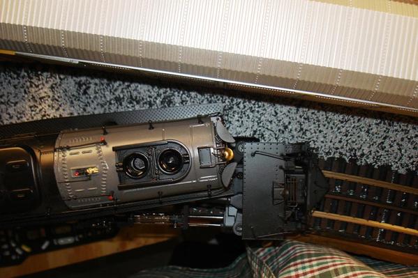
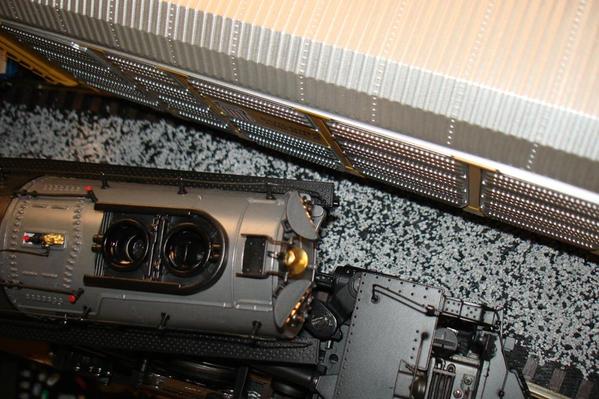
While filming the video below, I had the opportunity to measure the clearances between the Big Boy and auto-rack cars passing each other. The auto-rack cars are 20" long, and the tracks are 4-1/2" apart, center to center.
There was no problem when the Big Boy was on the outer Ø108 curves, as it really does not encroach much in the inner part of a curve, but I was concerned about its front end protruding too far and contacting the auto-rack when the Big Boy was on the inner Ø99 curves with the auto-rack cars on the outer Ø108 curves.
Well, it was close, but no too bad - at least a 1/4" clearance.
And my most recent video. Yes, I posted it elsewhere, but it should be part of this thread as well.
Thanks!
Alex
Attachments
Great!
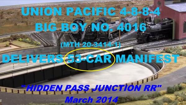
Alex, how many cars are you pulling with that
Big Boy. I counted 53
Very nice
Ken M
Hi Ken!
You counted correctly - 53 cars. The opening screen includes this bit of information, but I selected a color for the letters that makes them hard to read.
Thank you, and we look forward to you visiting us soon!
Alex
Attachments
Alex opens his house a number of times a year for all who can come by and view first hand what a marvelous layout it really is. I have been fortune enough to visit twice and am in awe each time. Thank you Alex for sharing your layout AND they technics you use to build and tweak it into the dream it is today.
An electronics magician, Alex comes up with ingenious ideas on how to get something to work the way he envisions it should.
And Alex, thanks for showing me the MTH remote capability to “Record/Play Back” what a neat feature, and so cool to watch it on Your layout!
Dan
St. Louis
Dan you are so right, if you come within 100 miles of this layout, you need to contact Alex. He and Judy will make your day....by the way, you will enjoy the layout also.![]()
Dan,
I am so glad you have enjoyed your visits here; we enjoyed having you over as well. And I really appreciate all the factual information you have shared with me on how real trains (currently) operate – most interesting and educational.
I have a video planned of the UP diesels operating in the diesel facility using the DCS Record-Playback feature as you saw – it will be called “UP Diesel Shuffle”, coming soon to a YouTube near you.
Roger,
Don’t let the few extra miles over 100 keep you away for long; we are anxious to have you guys visit us again, and Judy is ready.
And thank you both for your nice and considerate remarks.
Alex
Alex, This is Gary, Auburndale Florida. We talked on the phone right after you completed your Trestle Bridge back in 2011. I took several notes and still have them on building the trestle bridge. It is now 3 yrs later and I am just now getting to the trestle bridge. I was wondering if you ever wrote any instructions and building tips? If you did I would sure be interested in getting a copy. You mentioned an excel spread sheet in a very early post where you figured out all the lumber dimensional cuts. Would you be willing to share that also?
Thanks,
Gary
I just re-watched the Big Boy video.....it is fantastic!
Peter
Hi Gary,
Yes, I remember our conversation well. And yes, I wrote rather detailed instructions for building the trestle, and they were published in a 9-page article in OGR Magazine Run 256, April/May 2012. A printout of the resulting Excel spread sheet was also included. Whether you are able to get a hold of that OGR issue, don't hesitate to contact me if you have any questions.
Peter,
Thank you very much for you comment. That video did turn out well and a lot of people liked it.
Here is a link to that video:
Alex
Alex, Great video. I guess I must have missed this the first time around. Hope that you and Judy are doing great.
Thank you so much Alex, this is great. I found the magazine and article. Hopefully I can start working on mine soon. Will keep you posted.
Alex,
As you know I am also using Atlas track. I just wanted to tell you that I used your method of fastening the power to the track and it works perfectly. Also wanted to thank you for figuring it out and posting here for the rest of us. Can't wait to add your point indicators (after I get the switches wired that is, coming soon).
I used the 5/64" bit, ORG's #16 wire and the #0x1/4" pan head screws from Micro Fasteners just as you described. It got pretty easy to do after the first couple connections. It's only a 6'x16' layout and I only have my DCS hooked up right now, but it works perfectly also black rails and all, even with some of the still dirty, used track I have recently purchased (today may be cleaning day).
I also followed your method of track laying using wood blocks with notches for the rails. Drew the curve radius (radii?) with a compass attachment I had for a yard stick (O-63 is the biggest curve I have and O-54 the smallest). It came out pretty well. Had a small gap here and there, less than an eighth of an inch, but for the most part it fit very nicely. I am thinking the few gaps I had may have been due to the used track I had? I had to adjust some of the rails by sliding them one way or the other by about 1/4" or so. One rail would be uneven with the rest on the same piece of track. Atlas track and switches have been a little hard to come by lately, or I would have probably tried to use all new.
Anyway, thanks again for posting all the tips for the things you did while building your layout. It's helped me a lot. I plan to re-do all of mine in a year or two as I can afford to enlarge it, so your post here has been a great learning experience, especially since we are using the same track. That's a great way to connect the power feeds and will allow me to easily re-configure when the time comes.
Alex, this question is a couple of years overdue but when I first joined the Forum, I was checking out everyone's techniques, style of building and designing and I was impressed with the deliberate way that you built and designed your layout and also the incremental steps that you took when building. My question pertains to your spacers that you designed for your track elevation. What type of wood did you use, I believe I can do the same thing in creating the elevation but I'm kinda questionable on what type of wood stock did you use to cut the individual segments.
Alex, I love following your progress. It has been some time since I visited your layout due to health issues. Hope to get up that way again soon, maybe when there is a show near by. Keep up the great work.
That's a great video and a beautiful layout. You have really created a beauty.
I don’t know how I had the time to finish the basement and then the layout while I was still working! I have now been retired for almost three years, and I don’t have enough time to do all I want to do!
I apologize for not answering your posts sooner. I have been reading the “Hi-Rail, O-27 . . .” section o the forum almost exclusively, and did not see these posts.
Roger, Gary, Tom, Maershelangelo, Mike, Chris -
Thank you all for you very nice comments – they are much appreciated!
Gary,
Yes, please – do keep us posted with your progress on the trestle.
Tom,
Glad to see that some of my methods are working for you as well; and you are coming along fine. Hopefully, the Point Position Detectors will also complement your layout.
Marshelangelo, you wrote, in part:
"My question pertains to your spacers that you designed for your track elevation. What type of wood did you use, I believe I can do the same thing in creating the elevation but I'm kinda questionable on what type of wood stock did you use to cut the individual segments."
I used an assortment of mostly scraps of 3/4" plywood and some pine. I spaced the supports every six inches, and each is 1/8” higher than the previous support. This results in 1/4" rise per foot, or about 2% grade (0.25”/12” = 0.02). I used 76 supports for a total of 9-1/2” rise, which took about 38-feet of track.
One thing to keep in mind is that although the track may rise 9-1/2” (in my case) the clearance is not this at all. ![]() This 9-1/2” is from rail top to rail top, so we have to subtract the rail height, track ties, and roadbed surfaces under the track, and any other support.
This 9-1/2” is from rail top to rail top, so we have to subtract the rail height, track ties, and roadbed surfaces under the track, and any other support.
For the upper level, in my case, I ‘lost’ about 1/2" for rails and ties (Atlas track), 1/2" for the QuietBrace, 5/8” for the plywood, and 1-1/2” for the cross braces under the plywood; all of which added up to 3-1/8”, which left me with a net 6-3/8” clearance for the trains.
To support the grade track itself I used only the wood supports and the QuietBrace under the track. I tested the rigidity of the Atlas track over just the QuietBrace, and with the supports every six inches there was no detectible deflection with a 15 lb load applied at a single point between the supports. This would be the extreme, as heavy engine would not be supported by the track at a single axle, but the load would instead be spread over a foot or more.
Hope this helps, and good luck!
Alex
Attachments
Thanks Alex, you have been a great help. The position indicators are definitely in the cards for my layout! I might add, they just keep getting better too. I am changing things around a bit and hope to have things figured out and my mind made up pretty soon.
I don’t know how I had the time to finish the basement and then the layout while I was still working! I have now been retired for almost three years, and I don’t have enough time to do all I want to do!
I apologize for not answering your posts sooner. I have been reading the “Hi-Rail, O-27 . . .” section o the forum almost exclusively, and did not see these posts.
Roger, Gary, Tom, Maershelangelo, Mike, Chris -
Thank you all for you very nice comments – they are much appreciated!
Gary,
Yes, please – do keep us posted with your progress on the trestle.
Tom,
Glad to see that some of my methods are working for you as well; and you are coming along fine. Hopefully, the Point Position Detectors will also complement your layout.
Marshelangelo, you wrote, in part:
"My question pertains to your spacers that you designed for your track elevation. What type of wood did you use, I believe I can do the same thing in creating the elevation but I'm kinda questionable on what type of wood stock did you use to cut the individual segments."
I used an assortment of mostly scraps of 3/4" plywood and some pine. I spaced the supports every six inches, and each is 1/8” higher than the previous support. This results in 1/4" rise per foot, or about 2% grade (0.25”/12” = 0.02). I used 76 supports for a total of 9-1/2” rise, which took about 38-feet of track.
One thing to keep in mind is that although the track may rise 9-1/2” (in my case) the clearance is not this at all. ![]() This 9-1/2” is from rail top to rail top, so we have to subtract the rail height, track ties, and roadbed surfaces under the track, and any other support.
This 9-1/2” is from rail top to rail top, so we have to subtract the rail height, track ties, and roadbed surfaces under the track, and any other support.
For the upper level, in my case, I ‘lost’ about 1/2" for rails and ties (Atlas track), 1/2" for the QuietBrace, 5/8” for the plywood, and 1-1/2” for the cross braces under the plywood; all of which added up to 3-1/8”, which left me with a net 6-3/8” clearance for the trains.
To support the grade track itself I used only the wood supports and the QuietBrace under the track. I tested the rigidity of the Atlas track over just the QuietBrace, and with the supports every six inches there was no detectible deflection with a 15 lb load applied at a single point between the supports. This would be the extreme, as heavy engine would not be supported by the track at a single axle, but the load would instead be spread over a foot or more.
Hope this helps, and good luck!
Alex
Hey Alex, pardon me for the utmost case of extreme tardiness, I was looking over at your page one of the Hidden Pass Junction and saw that you needed a coating of some sort for your wall mural, (I apologize because this was on page 1 and you're on page 10 now) try Krylon Fixative, I believe it comes in a matte finish, maybe even a gloss finish but you can get this maybe at a local hardware store but definitely at an art store, it will serve as a protective for drawings, photos and paintings. I hope it will work on your mural depending on what type of surface you painted on. Once again, apologies for my tardiness, I didn't see that until my second time around reading. - MARSHELANGELO
Thanks to marshelangelo for reactivating this thread. My father introduced me to Marx/Lionel back around 1950 & this is one of the most impressive projects I've seen to date. I've read the 10 page thread & watched all the videos over the last 3 days. All the superlatives have already been used & all I can add is my own WOW! I've been using TMCC & DSC for over 10 years, but am new to OGR (thanks to LHS). I can't decide what my favorite area is; there are so many. It comes down to the Trestle, TT, & Subway Mall. I also like the eclectic style of weaving the Game of Thrones, Downton Abbey, etc. themes into the videos.
My wife has been after me to free up some storage areas & your under table cart idea is perfect. I plan on moving the swinging/hinged doors & attaching them to the end of each cart. When the carts are in place, they will be located under the table using 1/2" dia. tapered pins & bushings in each upper corner.
Thanks for the education.
To me, you are ingenierio/artista, a true Renaissance DaVinci!
Matt


