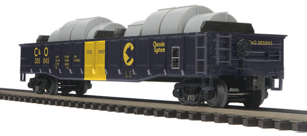
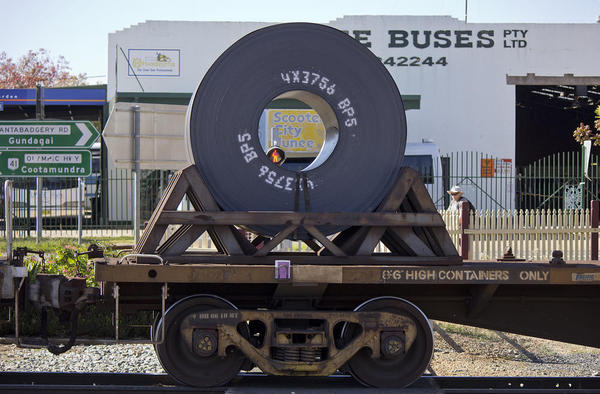
For your consideration, here's a close to prototypical guide to loading your normal (non-specialized) gondolas with coils.


Having once worked in a steel mill with coils (tin plating line, strip steel), I am always amused when I see cars like this.


20-98846


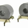
Bear with me and I will explain why.  AtlasO makes some very nice coils that are available as separate loads.  Weaver used to as well until their subcontractor quit and they themselves closed the business.  MTH might offer them as separate items as well.  Anyway, here's a photo of the AtlasO coils, which come in 2 sizes.


DSCN1149

The one on the left is fully 1.5" or 6 scale feet in diameter.  That is a huge coil and, in my somewhat limited experience, fairly rare in occurrence (maybe they've routinely made coils larger since the 1970's, I don't know).  I've seen smaller sized coils that went 60,000-65,000 lbs, but I'm ready to arbitrarily assign 60,000 lbs to the larger coil.  The smaller coil, still a scale 5 feet in diameter, will be assigned a weight of 50,000 lbs.


OK, so here's a regular (non-specialized) gondola 52.5 scale feet long that we wish to load with coils for shipment to a canning facility, automotive manufacturer, or appliance maker.  It's the mid-late 1950s, so coil covered gondolas are not invented yet (1960s for them).


DSCN1146


Note the markings, in particular the Capacity (CAPY) one.


DSCN1147


Yes, it says 140,000 lbs.  The LD LMT (Loaded Limit) marking next to it says 153,700 lbs.


So, if we consider our assumptions for coil weights to be correct, this gondola should be loaded with 2 of the larger (60,000 lbs) coils or 3 of the smaller (50,000 lbs) ones.  And you place them over the trucks so as not to stress the spine of the car.


If you arbitrarily make the big one 40,000 lbs. and the smaller one 30,000 lbs., you can place 3 of the large or 4-5 of the smaller ones into the gondola.  Again, they should be grouped around the trucks.  The next 2 photos are not strictly accurate - no tie downs.  But they illustrate the idea of coil placement in the gondola.


DSCN1150

DSCN1151


Of course, coil weights and gondola load limits vary, so you can't take this as dogma.  It's more of a guide.

Have fun and don't overload your gondolas! 


George


Attachments

Images (6)
  • 20-98846
  • DSCN1149
  • DSCN1146
  • DSCN1147
  • DSCN1150
  • DSCN1151
Last edited by G3750
Original Post

Replies sorted oldest to newest

Originally Posted by rex desilets:

Very nice.

I, and others, would like information-sketches, photos, of tie-downs, cribbing, etc.

Thank you Rex.  I'm not an expert on these by any means.  I worked at the end of a tin plate line and in the Strip Steel Works.  My job was to help cranes load and position coils.  I did not load train cars.

But, I can tell you that cribbing was probably wood and that chains or maybe bands would be used (with appropriate padding to prevent creasing the thinner outer layers of tin).  And as much as these coils weighed, the chains were probably irrelevant.  If the load did shift, chains or bands weren't going to do anything except snap like string.  More than likely if the load shifted, the gondola would immediately flip over.  Later today, I will post photos of the Weaver coils, which come in a cradle.


I'm going to explore the cribbing and tie-downs as I have to solve those for myself.


George

Last edited by G3750

Thanks John!  That is useful information.


I can recall that Weir-Cove Moving & Storage, one of the main shippers for Weirton Steel, always loaded no more than 2 coils on each flatbed trailer.  These were always tarped and chained.  One would be south of the kingpin and the other would be located over the trailers back (8) wheels.  The trailer had 2 axles with 4 tires per axle.


George

Coils typically were loaded at the car body bolster location for direct load transfer to the freight car trucks then to the rail. The underfame of boxcars, reefer cars, gondola and flat cars structural members consist of a full length center sill and side sills, crossties, crossbearers and end sills. The centersill sides are z shaped or I beams, with top and bottom covers plates welded together in the past riveted this creats a boxed structural member to carry torque,beading and shear loads. The crossbearers and crossties are I shaped structural elements that today are welded to the centersill webs and the webs of the side sill which are C shaped channels. The crossbearers are considered continuous beams because of the vertical plate welded between the inside faces of the center sill web, this plate is in line with the webs of the crossbearers. The crossties are not continuous beams there is not vertical plate welded between the inside faces of the center sill webs. The light weight (Empty Weight) of the car excluding the trucks and live load in this case the coil weights is transferred to the center sill by the crossbearers,crossties, side sill and end sill. Train line dynamic forces from the couplers are transferred to the center sill and side sill either in compression or tension also there are dynamic vertical forces(rock and roll) transferred from the body and truck bolters at the side bearing locations. All loads on the center sil are transferred to the truck bolsters at the center plate locations, using stress analysis the loads carbody, lading and trainline are combined in designing these cars. The sides of reefer cars, gondola cars and box cars are considered as girders in this design analysis. Side posts on gondola cars are panel stiffeners and prevent shear buckling. The picture of the car with the heavy coil loading between the body bolster(truck centers)would have caused the car to collapse, modern coil cars are designed for this this type of coil loading within design limitations. I forgot to mention the old tank cars small gallon capacity than today's stub sill tank cars had the same structural framing as that of the gondola type car framing. Older coal and hopper cars had a full length center sill and angle side sill and end sills, the hoppers were part of the center sill assembly. Their car body sides had vertical side posts and the exterior slope sheets generally had angle welded to then transversely to prevent bulging and possible collapse. All cars are designed using an elastic analysis( stress below yield point of the steel structural shapes and plates benging or allowable shear stress) no plasticity or permanent deformations also inroads are being made on fatigue anaylsis.

The actual stress(bending,shear,buckling,principal using elastic theory) are divided into the allowable yield stress or allowable shear stress(58 percent of yield stress) to determine the factor of safety against AAR recommended standards.

Last edited by John Ochab

As promised, here is a photo of the Weaver coil loads with wooden cribbing.


Weaver Coils

As you can see, the cribbing is totally unrealistic in appearance.  No little legs like those shown are going to hold up 50,000 lbs. coils, let alone 2 of them  .  It's hard to fathom, but coils of this size have incredible mass.  We're talking about 25 tons


Let me give you an example of a coil's mass.  It's 1972 and I'm the crane boy on the end of a tin plating line in Weirton Steel's Tin Mill.  I'm at the end of the line.  Perpendicular to the end of the plating line is a 50' bay holding a coil field.  Overhead cranes traverse the field, picking up coils from the plating lines, moving coils from one end of the building to the other, etc.  These are similar to gantry cranes, except that their rails are built into the tops of the building walls.  The capacity of these cranes ranged from 60 tons to 300-350 tons.  There were usually 3-4 of these in a bay.


One of the most common "hooks" for carrying coils is a device that looks like a 3' yoke with 2 arms hanging down.  Each arm has at its end what looks like half an automobile wheel hub (like something you would coil garden hose on).  The arms are hinged at the yoke so that they can be swung up and down.  As a crane boy, my job is to fit the far arm's hub into the center of the coil with my left hand.  I hold it in place using a metal crook.  With my right hand, I put the near arm into the hub.  I apply pressure on both hubs until the crane operator takes the slack out of hoist cable.  Once that happens, both hubs are engaged (the coil is still on the ground), and the coil is safe to move.  At that point, my focus is disengaging the metal crook on the far hub and getting out the way (quickly).  The crane operator then safely lifts the coil.


So I'm sitting on my stool waiting for the plater to finish a coil.  In the meantime I'm watching a crane rapidly bring a coil from one end of the mill to the other.  The coil is descending rapidly as well (this guy is in a real hurry).  As the coil descends, it collides with a coil on the floor.  The force of the collision pops the forward arm out of the coil's center, the coil swings backward until it is facing the floor, and then it falls about 5 feet.  I would estimate the coil's weight at between 40,000 and 50,000 lbs.  The boom reverberated for about 10 seconds and the entire building shook!


That's what I'm talking about when I say these coils are absolutely massive.


It is also highly unlikely that coils would be shipped as positioned - it would be too easy for them to shift out of these unrealistic cradles when the train starts or stops.


I would think realistic cribbing would look like 6"x6" boards placed several boards deep around the coil and extending to the sides of the gondola.  The coils would be shipped with their hollow centers in the direction of travel.  Chains would be required; tarps would be optional.


George

Attachments

Images (1)
  • Weaver Coils
Last edited by G3750
Originally Posted by G3750:

It is also highly unlikely that coils would be shipped as positioned - it would be too easy for them to shift out of these unrealistic cradles when the train starts or stops.


George,

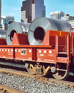
that was going to be my question: with model trains, the coils are usually positioned "sideways", probably because they look better


s-l1600


But you are saying this is not prototypical; the axis of the coils should be aligned with the direction of travel, so that the coils do not roll forward or backward with the train starting and stopping?  I would think that side-to-side rolling of the coils would also be lethal since they have so much mass; they would have to be blocked very securely?


What you are saying would also seem to indicate that coils would be hauled in gondolas with sides rather than on flatbeds?


thanks


david

Attachments

Images (1)
  • s-l1600

David,


I don't think it's prototypical (think is the operative word, I'm not an expert on this) for these types of gondolas to carry coils as shown in your photo.  I've seen photos of specialized coil cars that do carry coils pointed in that direction.  And not to nit-pick, but your photo is of cable spools or reels, which is a much lighter load.  But they certainly do look better that way.


Side to side rolling of these coils would be lethal - you are correct.  My guess (and that's what it is) is that a fairly deep wooden "well" of 6"x6" boards and cribbing would be constructed and placed on the floor of the gondola so as to be wedged in place.  The coil cars of the 1960s positioned coils perpendicular to the direction of travel.


Keep in mind though, the forward and backward jerking of trains is pretty dramatic (much worse than side to side), especially during switching maneuvers.  That's why cabooses were typically cut out of switching exercises and one reason why cabooses were eliminated altogether - too dangerous to the occupants.


As for hauling coils using flat cars or flat beds vs gondolas, I don't know.  I have read somewhere that coils were even shipped in boxcars prior to the advent of specialized coil cars.  I know that I witnessed many trailer trucks carrying 2 coils aligned as described.


There seems to be a prototype for everything if you look hard enough.  

My original post was about the number of coils and their weight as assigned to our toy rail cars.  The weight issues is an absolute.  You can't load a 140,000 lbs. capacity gondola with 8 50,000 lbs. coils. 


Maybe someone has photos of the cribbing.  I'd like to see that.


George

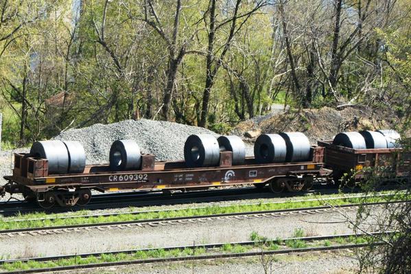
Well, I just took a good look at your second photo, Rex.


crcoilcar


The car to the right of the coil car is what I was talking about.  It seems to be loaded as I described.  We don't know the weight of those coils (the thickness of the metal, type of metal, density of winding) but apparently they are light enough to allow 3 over the bolster.  Obviously, 3 coils of aluminum (doubt that's what it is) of that size would weigh much, much less than 3 similar coils of tin-plated or galvanized steel.


George

Attachments

Images (1)
  • crcoilcar

Add Reply

Post

OGR Publishing, Inc., 1310 Eastside Centre Ct, Suite 6, Mountain Home, AR 72653
800-980-OGRR (6477)
www.ogaugerr.com

×
×
×
×
Link copied to your clipboard.
×
×