I do quite a few TMCC conversions, and I've been asked a number of times about improving the functionality of chuffing synchronized with the sound on the projects.  ERR has a chuff buffering board, but it's pretty basic, and it also isn't compatible with the new RS5 board they sell as the chuff input must be totally isolated with no common ground.  With that in mind, I set about coming up with a more complete design.


To start, I had a list of things I'd like my board to do.

  • Synchronize the sound and smoke chuff (no kidding!).
  • Run smoke fan continuously when locomotive stopped.  Smoke motor runs at lower voltage when stopped to have a better look of "idling".
  • Generate timed motor chuff output so short or long switch closures don't make the chuff generation look wrong.

Since I know when the locomotive is running or stopped, I decided to add a couple of features that I like to include in my conversions if possible.

  • Provide Rule-17 lighting control for an LED headlight, dimming when stopped.
  • Provide cab light control to turn off cab lights while moving, and on when stopped.

One other input is provided to allow turning the headlight off if the locomotive lights are turned off from the remote.  This is driven from the existing TMCC headlight output.


After looking over the logic, I decided that a PIC processor would probably be the way to make this all happen.  I dug out my proto board and started programming up a PIC12F1501 (happened to have it on hand).  It's been a real learning experience getting it all working, and I have a little better understanding of the capabilities of these inexpensive yet very capable parts.  I've also managed to travel down a number of dark alleys in the quest, and I have a lot better understanding why the datasheet (or should I say encyclopedia!) for this part is almost 300 pages!  There is an amazing amount of capability packed into this 75 cent part, and I have only scratched the surface with this project.


Please note that this is a "work in process", I just figured I'd post and let you folks critique the progress so far, and perhaps offer some useful suggestions for improvements before I go to press.  I still have a ways to go before I'll have a completed board, but here's where it stands now.

Last edited by gunrunnerjohn
Original Post

Replies sorted oldest to newest

It is neat.  You should be able to sell a lot of these.  I was pondering how folks like their smoke with a lot of the recent upgrades for smoke posted.  The problem with the fan driven Lionel upgrades is they really don't puff and have the full synchronization that MTH has with the integrated approach.  And you certainly don't get the flexibility to change chuff rates easily.


Adding a selection for 1, 2 or 4 puffs if possible would make this a neat additive for upgrades to TMCC if cost is reasonable.  G

I did think about programmable chuffs, but I can't figure how to do that properly. I'm still dependent on the mechanical or reed chuff switch for timing.  The problem is that as speed changes, you'd be hearing odd timing on the chuffs, and I suspect that would be a real turn-off.  If someone has a neat idea of how to generate multiple chuffs from one switch closure and keep the timing right, I'm all ears, I can't imagine how that would work.


Once you get running at a steady speed, it's pretty easy in software to generate the chuffs, it's getting to the speed without it sounding bad that's the hard part.


That being the case, I figure that I'll do some neat stuff that can be done properly with what I have to work with.  There's always the next project if I come up with a way to properly address programmable chuff rates.  One way would be to use an encoder on the flywheel and count pulses like MTH, we know that works...

That looks great! I don't know enough to offer any suggestions, wish I did. I have read a couple articles on the PIC chips in Garden Railways and they are pretty neat little chips. Had no idea the data sheet was 300 pages though, that probably makes it way over my head. They sounded a bit simpler in the articles. Thanks for sharing the project with us and I hope you keep posting your latest developments.  

Provide an option to leave the cab light on when in motion.  I'm not a fan of the cab light going off when in motion, perhaps it's due to all my stuff being old enough that if there's track power, there is a cab light, and I like it that way.  Maybe you can see if you can sense direction, then you could also change the lamp colors from green to red on the front and red to green on the back when the loco goes backwards.  Or even a way to program marker lamp color options, off/green/white, for the train status.  I think that would get a bunch of the scale guys on board.

You should download the datasheet, it makes for good bedtime reading.


PIC12(L)F1501 8-Pin Flash, 8-Bit Microcontrollers Data Sheet (04/02/2014)


If nothing else, it'll mess with your brain!


sinclair, I am doing the cab light the same way that Legacy does them, it seemed to make the most sense.  If you want to leave it on when you're moving, probably best to simply wire it to power and not through this board.


Sensing direction would take more inputs, that's not in the cards for this round.  However, I have the basis for a more involved controller that will have expanded capabilities, I figured to get my feet wet doing this one as it's a feature set that seems to be in demand, and it's my first PIC project.


Pete, the Rule 17 isn't done correctly on any model that I'm aware of, Legacy and DCS just dim it when the engine is stopped and crank it up when they start moving.  Trying to dim it for oncoming trains is WAY outside the realm of reasonability with present capabilities.  I can't even imagine what that would take to do properly, but suffice to say that I'm pretty sure none of the control systems have the capability do to that as of now, and I'm sure this little project won't be trying!


Yep, if the locomotive is chuffing, I figure it's still moving.  When it stops for two seconds (arbitrary value I selected) I figure it's stopped. Obviously, I can change that value to anything I like, but two seconds seems like a decent value for now.


I also selected a value of 100ms for the smoke fan to run for each chuff, it looks good on my bench test, but again I'll see how it looks in a real locomotive and fine tune it if necessary.  When the chuffs get to be 100ms apart, the fan run continuously.


The headlight is an LED directly driven by the PIC port and I use PWM to change the intensity of the headlight.  I figure when I build my first prototype to go into an engine I'll fine tune the PWM parameters, right now I'm using a pulse width of 15/256 for the low intensity and 255/256 for full intensity.  It looks pretty good on my board, but I might make the low a bit brighter when I see it in place in a locomotive.


Speaking of motor leads, in the future I'm thinking of coming up with a motor connection that will not only tell me when I'm moving, but from the polarity I'll be able to tell the direction as well.  That's for a future project.  I could do it with two opto-couplers, but maybe I can come up with something a bit neater.  It will have to be totally isolated, so there'll have to be optics in there at some point.  Basically, it would look like a dual circuit for the existing headlight input with both polarities covered, and they'd feed two ports the way I see it now.


Originally Posted by David Nissen:

On my TMCC conversions I like to have an indicator light to let me know that the smoke unit is on so that I don't run it dry. I usually add a red smoke box light in the cab when the smoke is on. I would be open to any other ideas. It would be ideal if the smoke shut off when the fluid ran out.

I have no way of sensing the fluid level in the smoke unit, so I'd have an issue there. 


 John...

 Do you think you could sense fluid level by current draw of the element ?

 The less fluid the more current draw ?  might be something to bench test one

 day " in your spare time "..  Just a thought....


That's way beyond what I'm doing this pass.  I don't know that current draw is a reliable indicator in any case, and I'd actually expect it to go lower when the element is dry.  TAS used to sense it using a thermistor next to the heater, when the temperature started to rise, they knew the fluid was getting low.  I have no idea how well that worked.  Truthfully, I just keep an eye on the locomotive and add fluid when the smoke tails off.


Well, I think I have a first cut at the real schematic and a trial layout of the boards.  They ended up being 1.1" x 1.2" in size.  The PIC chip is a DIP chip as it will be socketed so I can remove it for programming.  I thought of including programming capability on the board and using an SMT part, but by the time I got the extra connector on the board, it didn't really save me any real-estate.

 I can see I have a lot to learn about the schematic capture program, not to mention the board layout feature.  I had to define a number of parts so that I could complete the design, so it was slow going.  I guess after I have done a few boards, I'll have a selection of the common things I use that I can pick from.


Last edited by gunrunnerjohn

I'm fine tuning the design, a couple of the components were the wrong size footprints.


I also decided on another "feature", when the locomotive stops, I'm going to run the fan on a lower voltage so the idle smoke comes out slower and not like the full speed running.  All it took is swapping a couple of pins and programming up the PWM for the smoke motor output.  I think that'll be another little nicety that will enhance the function.  At this point, I'm trying to look it over carefully and see if there's anything I missed, then I'll look for a place to get the boards at a reasonable price.


I think there is a much simplier way to get chuffing smoke by installing either a diode or capacitor into the circuit between the smoke unit and the TMCC board that controls the smoke unit. One of the Lionel Service Stations has been doing this for a couple of years now.


Also it was mentioned that ERR is now suppling RS5 sound boards but there was nothing about this on their web site.

This is a solution, but it still is not ideal.  It stops the fan when the switch closes to generate the chuff.  This limits you to what ever the manufacture chuff rate is (normally one). 


It doesn't dynamically stop the fan like MTH does which gives a very distinctive puff of smoke on the chuff, it is not adjustable, and you run the chance of stopping the engine when the switch is closed which keeps the fan off despite the heater still being on.  G


These are installed in the locomotive and there is some wiring involved by necessity.


As far as adding a diode to mux the chuff, all I can say it "good luck".  If you use the new RailSounds 5 board from ERR, that is no longer a solution as both chuff inputs must be totally isolated from frame ground.  The chuff switch in that installation MUST be totally isolated from any other circuit, which is why my design has an opto-coupler to output the chuff. 


I also don't see where that diode runs the fan at idle, or provides the enhanced lighting effects I'm adding, but I guess I just don't understand the diode fix well enough.


Last edited by gunrunnerjohn

The new single board RailSounds Commander is RS5 based.  I got that direct from Jon Z. at ERR, and using the new boards they do have the improved sound as well as the expanded crew-talk of RS5.  The difference over the older 2 board RS Commander is pretty obvious when you use them.


As far as my comment about the reed switch, you need to actually read the RS Commander manual. 


chuff sw

Clearly, the "simple" fix of using a diode to the smoke unit motor is not possible with these boards.

Attachments

Images (1)
  • chuff sw

John,


Your new board is great. May need to send some work your way.


I really like the sounds from my RS5 engines, but I don't like how Lionel set up the steam whistle.  You have no control over the whistle; when you press the whistle button you get one of three preset sounds.  i have found no way to sound forward, backing, or crossing signals. Does the new ERR boards have this same RS5 feature?


Thanks. Ron

Last edited by CAPPilot

Well, it's in the hands of the vendors now!  I ordered the parts and the boards for 10 sets, it'll be interesting to see how long it takes to get them.  Digikey has already confirmed shipping for the parts, so I'll have those long before the boards.  It wasn't as bad as I thought, $12/ea shipped for parts and boards.  Now I just have to see how long it takes me to assemble them when I get them, it's got to be faster than my hand wiring of the initial prototype!


I ended up using DipTrace software for the schematic capture and board layout.  Not perfect, but I'm getting better at creating parts outlines so I can do a board layout.  I wish they had more parts in the libraries, it would make the task easier.


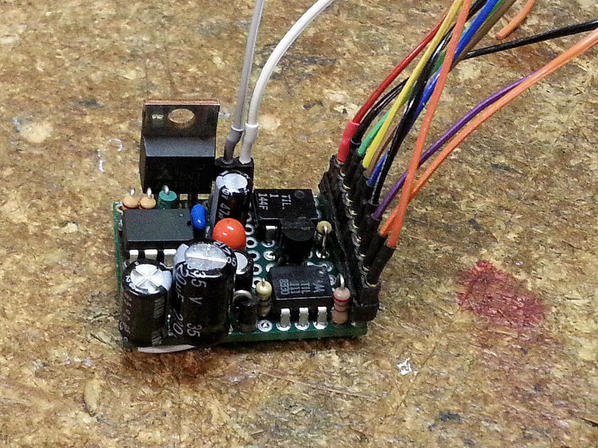
Here's the prototype that I built to make sure the circuit worked.  Good thing as I left out a couple of things, glad I took the time!  The parts are obviously different as the real board is almost all surface mount, but the functions are the same.


I'm going to put this into a locomotive, might as well get some use out of it.


Super-Chuffer Prototype

Attachments

Images (1)
  • Super-Chuffer Prototype

As soon as I figure out what I have to stick it in.  I may have to do one of my pending upgrades to have a test victim.


I did order all the stuff for the real boards, and I'll have everything but the boards tomorrow it looks like.  I'm not sure when the board house will ship the boards, they're the pacing item.  It sounded like they have a pretty quick turn, we'll see...


Now that it's run on the bench, I'm kinda' eager to see it in a real locomotive.

Welcome to the club! I designed the TAS Puff 'n' Chuff circuit board PIC and software along with Lou Niederlander who did board layout. If I remember right it had the thermistor overheat control, switch input for chuff and  when the engine wasn't moving the smoke level was cut back. It also had steam or diesel mode. Diesel simply didn't chuff. 

I did work on a multiple chuffing circuit for somebody. You can divide the time between switch inputs for mulitple chuffs (2, 4 or whatever) but you have to guess until you get the second one.


I posted a thread in the general forum with a brief test video of the prototype board.


I don't control the smoke element power, so cutting back the heat isn't an option, but I do drop the fan speed.  The thermistor would be nice, but that not only requires controlling the heater, but also modifications to the smoke unit.  I didn't want to go there, maybe next time.


I thought about the multiple chuffing, but as the speed changes, it would be out of sync until it caught up, and that would sound very odd.  One way that I considered, and may yet do in the future, is to do a moving average and generate the chuffs from that.  That would allow smooth transitions between speeds without the spacing between chuffs suddenly changing in a step.


All things are possible, I just figured to start with a basic capability that I, and apparently quite a few other folks, would like to have.   I'm also getting up to speed on how to use the board layout tools, and to do a proper layout for manufacturability.  I'd rather learn those lessons on a small project and then move up the scale.


Originally Posted by gunrunnerjohn:
Let the Peanut Gallery load up and fire!

From the video thread, your regulator is apparently getting quite hot(?). 


In looking at the 5V regulator loads, you may be biasing the transistors too hard.  For example, on the headlight input, a 1K load is a 5mA full-scale swing.  You don't need such a high operating point to drive a PIC input.  Also, why do you need an opto (vs. just a transistor) as the grounds appear in common. On the output side, 470 base resistors mean full-scale swings of 9 mA.  I realize you want to drive the transistors into saturation but I don't think all the loads need so much base current.  If so, perhaps for a dime or so more per affected switch you could use an N-Fet which would require zero current and use the same SOT-23 (or that's what it looks like) footprint.  Also, the 330 ohm into the RS Chuff opto seems a bit low unless that opto output really has to drive a lot of current.


Bottom line. I'd think you could reduce regulator current by, say, 25+ mA which might bring the heat issue under control.


Add Reply

Post

OGR Publishing, Inc., 1310 Eastside Centre Ct, Suite 6, Mountain Home, AR 72653
800-980-OGRR (6477)
www.ogaugerr.com

×
×
×
×
Link copied to your clipboard.
×
×