I recently purchased a used PS-3 Premier A-B-A set that was dead on arrival. Both A units are powered. Tried the usual trouble shooting to get it to start and determined the board was bad. I replaced the master board with a PS-3 board purchased from ebay a while back, that came out of a PS-3 Railking 2-8-0. The boards, physically, looked to be the same. I installed it then downloaded the proper sound file for the diesel. The download completed and she started up fine and sounds great. The problems I am having are: (1) The front coupler will sound but not fire. (2) The slave board in the second powered unit sits dark. I'm thinking there must be a flash code that needs downloaded that was not provided with this engines sound file or this board was not capable of holding the entire file size of the download. One other separate issue, there is the smell of a component burning when the smoke unit is turned on. It's very hard to tell if it's coming from the smoke unit itself, or the circuit board because their so close together. The element measures 8 ohms and is not grounding out anywhere. Will the element over heat and create the smell if the wick is not touching the element to help dissipate heat?


Original Post

Replies sorted oldest to newest

You have to load the FLASH files and the sound file to get full functionality.  The boards are the same board.

Hard to say about the smoke unit, I'd disconnect it to get everything else working, and then make SURE nothing is wired wrong for the smoke.  The smoke circuit is the same for diesel and steam, so providing it's all wired right, you shouldn't be getting smoke from the circuitry.

If you download the PS/3 sound file, it should be a ZIP with two files in it.  One will be the chain files, and the other is the sound file.  Here's an example.

You need to load both, here's the DCS 5.0 instructions on how to load chain files, start on page 7 for chain files.

DCS 5.0 Loader Instructions

Attachments

Last edited by gunrunnerjohn

I'll be honest, I haven't replaced anything on a PS/3 board as we have no documentation.  I don't even know where they are, and I've never seen the PS/3 slave board.

FWIW, I believe I mis-spoke earlier, the steam and diesel boards are not the same, so I'm not sure you actually used a steam board in a diesel. I was, of course, thinking of the PS/2 boards.

I think my head was in a dark place when I said that as I do know the difference!  The connectors are totally different, so if you have a diesel, you didn't put a steam board into it.

PS/3 Steam Tender Board (With Supercaps)


PS/3 Diesel/Electric Board

Attachments

Images (3)
  • mceclip0
  • mceclip1
  • mceclip2

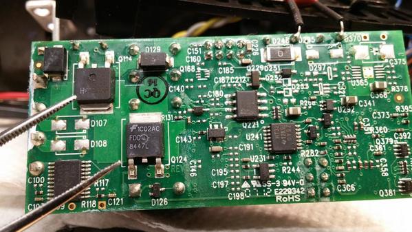
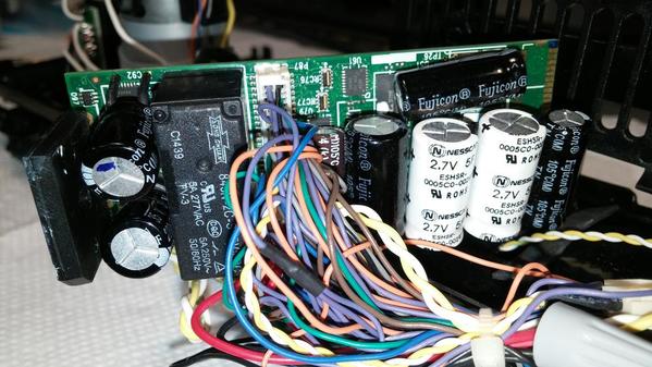
0402171844 Very interesting, John, because the identification sticker on the PS-3 master board's relay housing says NWD080  Christmas #1225 which is a RTR steam engine from the Railking 30-4229-1 Christmas Express Set. The Christmas ES44AC Diesel is road number 1201. Also the front coupler or slave board would not function until I downloaded the diesel flash files. Which if it came out of a diesel at least the front coupler would work. It would be interesting if someone who has one of these 2-8-0 steamers would open it up and tell us what the board looks like. Getting back to the slave board, I attached some pictures of the board and if I am correct in identifying the FET's it looks like there are two at the tips of my tweezers. Not sure though which operates the coupler or the smoke unit. The one has the paint within the part numbers missing which may have happened if it got very hot. Looks like their very easy to replace. One has #AA52HA the other #1C02AC. Would the part numbers help identify which operates the coupler?0402171804a

Attachments

Images (2)
  • 0402171804a
  • 0402171844
Last edited by Dave Zucal

I can't explain what the sticker is about, all the PA/3 steamers I work on have the steam board.  The only way I can see that being the diesel style board is if all the electronics was in the locomotive and they didn't need the two-board set.

You're pointing to the drive FETs, the coupler FET will be one sized like the one indicated below.

Attachments

Images (1)
  • mceclip0

After a closer look, if I purchase a very small soldering tip, I may consider tackling it. Can they be tested in circuit to tell which is bad? I do have a set of smart tweezers model ST5C, but not sure if the will tell me anything. I would also have to be sure the board is totally discharge as a precaution. Do you have a part number for these FET's, John? It's small but looks like maybe #44t.

WOOOOO Nelly!  FIRST, PS-3 Diesels and Steam Boards are not the same.  The PS-3 STEAM is a 2 board set up. You must have a Boiler board in the mix.  The boiler board has the Motor Drive FETs and Smoke unit parts.  SECOND the harnesses are different, so how did you do all this?  Third, putting a Diesel code into a steam board won't include code to communicate with Boiler board.   I am curious what you did here?   G

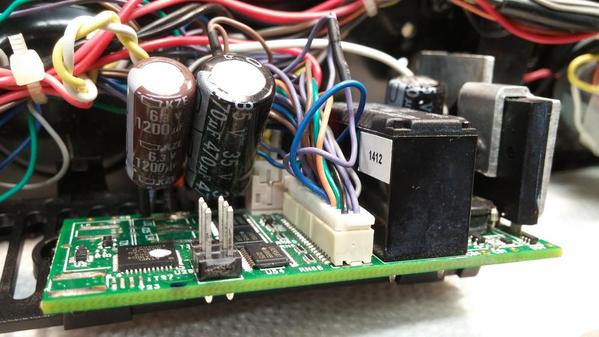
GGG, here is a picture of the master board that I used to replace the dead board that was originally in the lead A unit. It's identical to the one I replaced. The reason for my post was because I remembered reading, here on the forum, that a PS-3 "steam" board could not be used in a diesel. What I didn't know is if the reason was because they were physically different or being physically the same but working differently internally. What had me confused was an orange colored sticker which is on the side of the relay, behind the wire harness in the photo, that is stamped with "NWD080 Christmas #1225". When I looked it up I found that was a 2-8-0 steam engine. After downloading the correct sound file the flash code that was in it would not operate the front coupler or the slave board. This lead me further into believing it came out of the boiler of a 2-8-0 steamer. Could MTH have used these boards in the 2-8-0 Christmas Exspress boilers?0401171954 

Attachments

Images (1)
  • 0401171954

MTH made a RK SD70ACe Christmas Train.  That is a Diesel Board.  The front coupler will not fire unless there is a rear coupler in the mix.  This is awe shoot found out later.  So you need to add a load resistor to the Rear Coupler wire on F-3 A units that are run by themselves.   As far as the Slave not working, it may be bad.  Or the harness between the 2.   Did you reattached the large white Ground wire on the LEAD A PCB when you put the new board in?  G

G, then MTH may have stamped the wrong road number on the sticker, because the SD70ACe's road number is #1201. The two issues I had in the end was an electrical smell coming from the lead A unit when the smoke was turned on and the slave board sending constant voltage to the coupler on the second A unit. I resolved the issue with the electrical smell. When I originally added fluid, I only put about 8 drops in. When I opened up the unit to inspect it, the wick was still very dry and looked like it was never used. I soaked it up good and only run it now on medium. No more bad smell. I believe it may have been the first time the elements were used. As far as the coupler goes, I have to leave it unplugged. I was going to re-download the flash, but John believes it more likely a bad FET which looks pretty hard to replace and identify which one runs the coupler. Should I try adding the resistor and what value?  And yes, I added the white wire. Would you be interested in repairing the original board, if possible? I heard your very good at repairing boards. 

Last edited by Dave Zucal

My mistake was the ES44 30-20257-1.  If the Diesel board is dead, probably no repair.  I have been successful with lights, motor fets, and smoke fan/heat, but not dead boards.  Maybe the slave can have the coupler fixed, I also have a slave board.

Does the Lead A have the dummy coupler or real coupler installed?  If dummy then add a 4.7K resistor into the rear coupler molex plug.  This will simulate enough or a load to allow front coupler to fire.  G

GGG posted:

WOOOOO Nelly!  FIRST, PS-3 Diesels and Steam Boards are not the same.

I already pointed that out George, but only after I mistakenly thought I was talking about PS/2.   He appears to have a diesel board, but he says it was labeled for a 2-8-0 locomotive.  Were there any PS/3 steamers with the electronics all in the locomotive so they could use the diesel board?

BTW, do you have any information on the FET locations for the PS/3 boards?

Last edited by gunrunnerjohn

G, the front coupler on the "master board A unit" began working after installing the proper flash code. The front coupler on the "slave board A unit" is the one that stays energized. Both A units rear couplers are dummy couplers. Just for the heck of it, I'll try the flash code download again after I'm done eating breakfast. I'll post the outcome. 

No switch George, just the switch for DCC or DCS. I did test the coil coupler as you suggested and it does operate correctly jumping off of the coupler plug in the lead "A" unit to the coupler in the trailing "A" unit. Thanks to you when I did that a light bulb went on in my head that asked the question, why couldn't I just use the PS-3 master board's abilities of operating 2 couplers instead of depending on the slave board to operate the trailing units coupler, then not having to repair or replace the slave board?  So I ran a test to make sure the diesel A-B-A chain files not only sent signal to the slave board to open the trailing unit coupler, but also to the plug that is on the wire harness that would feed a rear coupler, if the board was being used in a modern diesel. Well it does provide two ways to control that coupler. My guess is that the reason MTH uses the slave board is the limit of only having 10 wires going to the trailing unit.  If I can't use two wires in the tether to get back there, I can just add a pair of thin wires with mini servo plugs to that coupler.

  1. What is the road & cab number of this set?
  2. Make sure you have this following DSP code flashed to the lead A unit: engine-hdr-3052.srec
  3. Make sure you have the following FPGA code flashed to the lead A unit: mth_fpga-hdr-3007-BA.srec
  4. Make sure you have the following BOILER code flashed to the lead A unit: boiler-hdr-2337.srec

You can load these with the loader program over the rails, one at a time, power cycling the TIU for ~10 seconds between each of the successful loads. 

It sounds like the coupler drive FET on the slave board is blown.


Add Reply

Post
The DCS Forum is sponsored by

OGR Publishing, Inc., 1310 Eastside Centre Ct, Suite 6, Mountain Home, AR 72653
800-980-OGRR (6477)
www.ogaugerr.com

×
×
×
×
Link copied to your clipboard.
×
×