
In another topic about sharing AC and DC commons here (Any reasons for separating AC and DC grounds?) the subject of Arduinos, ITADS, Relays etc, came up. I know this has all come up before in pieces here and there, but I though it might be good to have a single thread where this was all discussed.

One of the questions that I don't think was ever answered was which of the devices below would be the best choice? (Picture shown below posted by Stan2004) Or should something else be used? If you have used any of these devices, how did you mount them on your layout? Did you build an enclosure for them, hide them in the scenery, install them between the ties in the track, etc. (pictures welcome)?


Anyway, what are your thoughts, experiences, suggestions etc. on all this? Other methods also welcome.

Last edited by rtr12
Original Post

Replies sorted oldest to newest

I put a signal relay together for a friend's  setup.  I have actually been able to put both an Arduino and IR board under the track.  I drilled two small holes for the LEDs to poke through and hot glued it on.  I also drilled a tiny hole for the sensitivity screw.  I don't really have good pictures.  I used a plasticville  tower for the relay and VR. IMG_3346IMG_1388

Attachments

Images (2)
  • IMG_3346: To the left you can see the IR board and the arduino is under the styrene guard
  • IMG_1388: Tower containing the relay and VR

That is a fantastic video showing "real world" issues with IR sensors.  Before you lighten your wallet with the "other" type of sensor, I found yet another version of this "other" IR method that would probably be easier to use.  I'll write it up with some photos later today...

As you've probably seen, there are indeed relay modules with Time-delay capability for a dollar or so more per channel than a basic on/off relay.  Even the off-the-shelf ITADs need this hold-timing capability to catch the gaps between cars...and to hold the relay for the occasional dark car that can introduce a relay gap of several seconds (as your video shows).

This delay can be done for, say, 25-50 cents per channel using assorted parts allowing you to still use the 4-channel relay modules.  So it comes down to how much fussing/soldering/messing with components you want to do.  I've shown this hold/delay circuit (e.g., transistor, resistor, capacitor) in previous threads on rolling your own ITAD so I can dig it up or just re-draw it which might actually be faster! 

Brendan,

That looks very nice. Thanks for adding your project to the thread. Do you by chance have a picture of the top of the track? How does it work? Any problems with the space between cars?

John H,

I really thought those would work better than that from my bench fiddling, but that is not the same as actual use testing as you have done. A timer might be a good addition to those boards. I might be off here, but I think by putting an Arduino between the IR sensors and the relays you might be able to add the timers needed for drop outs. I was wondering about dropouts between cars though. Did the relays work ok connected directly to the IR boards? 

I was hoping Stan would be by to provide his wisdom and expertise. I think he will eventually. I'm sure GRJ, JGL and all the other electronically wise could add a lot as well. Oops, I see Stan is here already.

Last edited by rtr12
rtr12 posted:

Brendan,

That looks very nice. Thanks for adding your project to the thread. Do you by chance have a picture of the top of the track? How does it work? Any problems with the space between cars?

John H,

I really thought those would work better than that from my bench fiddling, but that is not the same as actual use testing as you have done. A timer might be a good addition to those boards. I might be off here, but I think by putting an Arduino between the IR sensors and the relays you might be able to add the timers needed for drop outs. I was wondering about dropouts between cars though. Did the relays work ok connected directly to the IR boards? 

I was hoping Stan would be by to provide his wisdom and expertise. I think he will eventually. I'm sure GRJ, JGL and all the other electronically wise could add a lot as well. Oops, I see Stan is here already.

Thanks.  Since I built for someone, I don't have it in front of me.  I am going to be able to see it Friday and plan to take more pics.  I use the arduino for exaclty as you say - a delay to eliminate dropouts.  I could have done it with parts, but the arduino can do more if needed.


Brendan

Last edited by Brendan

Hi rtr12

Here is a thread where Stan2004 and Gunrunnerjohn help me with IR build.

https://ogrforum.ogaugerr.com/t...76#48171004101674276

This design or if modification will be incorporated into the Super O permanent layout for use in gates and signals. Here is the thread with an mp3 player and similar setup. Page 6 of the thread has the MP3 hook up instructions.

https://ogrforum.ogaugerr.com/t...tical-sensors?page=6


I tried the bottom approach, but had to be closer than the axles to get a response. I think that might be because they were black. It also seemed like I had to be closer to metal than plastic. Stan or Brendan, can these sensors be paralleled so you could have a distance between them to make up for the gap between cars? I have trains running both directions all the time, so I would have one at each end of the block for signals. I'm enjoying this and all the help is making it possible.

John H posted:

Stan or Brendan, can these sensors be paralleled so you could have a distance between them to make up for the gap between cars? I have trains running both directions all the time, so I would have one at each end of the block for signals. I'm enjoying this and all the help is making it possible.

For the gap, the best solution would be to add a delay using res/cap/tran as Stan2004 mentioned or an arduino.  So long as you have an open collector/low input for the relay, you can have as many IR sensors as you want.  In the setup I did, I used two - one for each side of a crossing.  Ideally, a current sensor combined with the IR sensors gives full coverage of a block or section of track


Brendan

Last edited by Brendan

Thank you NVOCC5 for digging up those links to earlier threads on roll-your-own IR detection.  Lots of posts to wade thru but it does describe how to perform the ITAD-like time-delay using inexpensive parts if you want to use the ubiquitous $1 per relay modules. 

Or as you identified there are off-the-shelf relay modules with delay capability; though I must point out you need to read between the lines to be sure you are getting what you need.  You run into terminology like delay-on, delay-off, cycle-timer, multi-function timing, etc. and then some listings are nothing less than cagey in detailing if you need an active-hi or active-lo trigger to activate the delay!

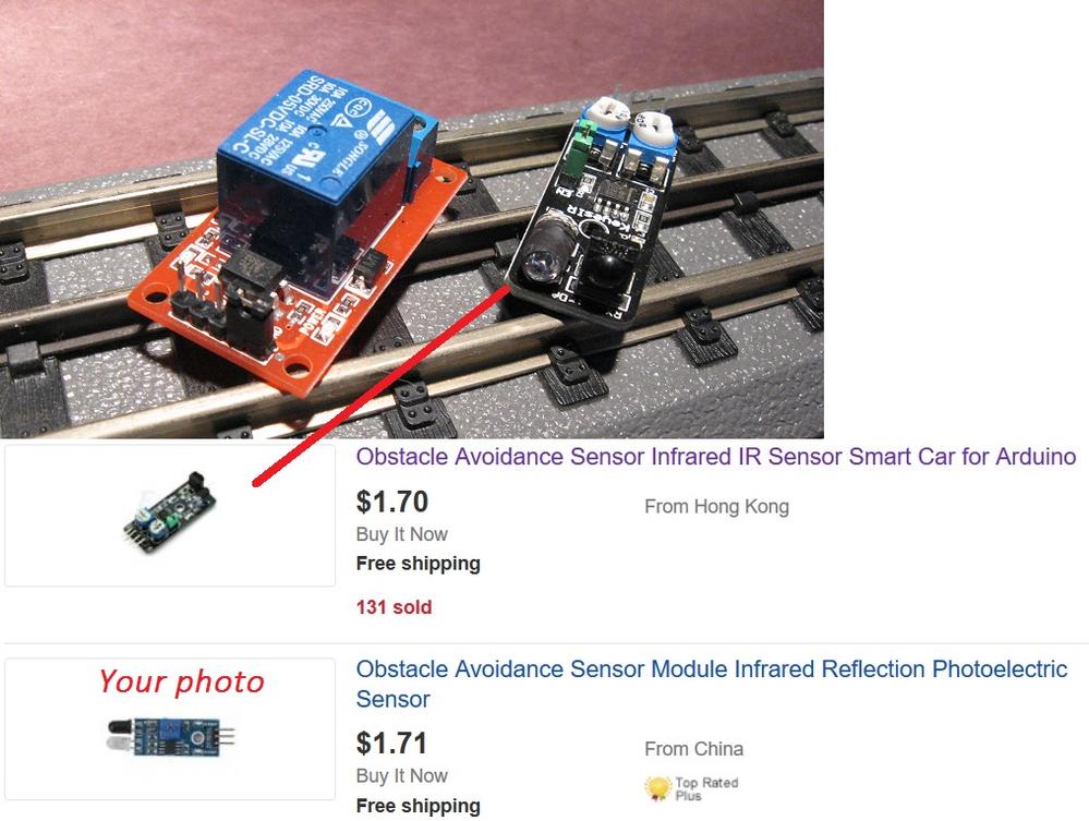
So if you are not getting adequate sensing distance or sensitivity the alternate IR modules can indeed provide better performance.  Some of the posts in the thread links describe the benefits of using modulated IR beams and as I posted earlier, these alternative modules are reasonably priced.  One hassle with the example I showed is you have to manually "tune" the transmitter LED which is sort of a nuisance.  But now I see modules that don't require this extra step. 

ebay modulated IR modules

I have personally messed with "A".  But now it's 2017 and I found B, C, and D on eBay without looking very hard.  I believe these would be better choices but have not used them myself.  Perhaps someone else can attest to their suitability for occupancy detection.  I ordered a "B" and will play with it but it will take a few weeks to get here.

As Brendan points out you can generally parallel multiple detector modules so that if one or more modules is active, it will trip the relay module.   As he points out the detector needs to have a so-called "open-collector" output which allows multiple module outputs to be electrically connected together - if 1 or more modules is triggered, the relay trips).  Otherwise, you can add a 5 cent diode to each module output to "make" it into an open-collector type output suitable for driving the relay module.

Additionally, if you like to experiment you can also drive multiple LEDs to spray the passing train with more IR energy.  IR LEDs of the type used on these module run maybe 10 cents each.  Yes, you have to fuss with more discrete components...but if you're going to de-solder components from the modules to better place them under the track or whatever, then that's another option.  This would increase the effective sensing distance...or for the same sensing distance improve detection of the dark surfaces.

Another option used by some off-the-shelf sensing suppliers is to shoot the IR beam across the track and let the train break the beam.  This is a MUCH simpler electrical problem than sensing the reflection.  Of course you must now mount a component on each side of the track...but by aiming the beam diagonally across the track you do not have the problem of gaps between cars.  This can relax the need for a time-delay.


Attachments

Images (1)
  • ebay modulated IR modules
Last edited by stan2004
stan2004 posted:

Or as you identified there are off-the-shelf relay modules with delay capability; though I must point out you need to read between the lines to be sure you are getting what you need.  You run into terminology like delay-on, delay-off, cycle-timer, multi-function timing, etc. and then some listings are nothing less than cagey in detailing if you need an active-hi or active-lo trigger to activate the delay!


I have tried several of these delay units and the issue I ran into with the delay-off units was that even if it has a continuous low (or high as the case may be) signal, it doesn't stay on past the delay time - it shuts off.  It turns back on right away, but that is of no help.  

Another detecting device is the one Geoff Bunza over at MRH came up with http://model-railroad-hobbyist.com/node/26133  I built a few and they work good in different lighting conditions.  I was looking at using smd photo transistors, one mounted to the roadbed and the other between the ties.  

 It willbe interesting to see your results with other IR units.

Brendan

Last edited by Brendan

Hi Kris,

Thanks for the links, I remember that thread now, it was a good one. Sorry for the late reply, my car and I have been a bit under the weather the last couple of days. I'm doing better than the car, something about a throttle something or other. I have applied for a 2nd mortgage so I can get it out of the hospital sometime this afternoon, I hope.

Some good information posted here so far, I am going to try to read it now, unless something else goes wrong... I haven't read the Arduino article from Geoff Bunza, but I have downloaded it to read. It looks good. And I still need to check out the new things Stan found above as well. I already have a couple of A's on order. I also have some current sensors that were mentioned and also discussed in another recent thread, but haven't tried them yet. I filed them away ad forgot about them until reading the other thread a few days ago. I am getting a real backlog here.

There is another thread about the actual ITADs also going on now. I just read a post about having an emitter on one side of the track and the detector on the other. I was fooling around with something like this a year or so ago and got sidetracked. I think this might be a good 'roll your own' option for this discussion as well.

At the time I also got some photo transistors and I did try some photo resistors with an Arduino for a train speed sensing project. Those did not work very well, but I only had the photo transistors working on the bench as I recall, didn't try them on the track. My 20x4 LED panel for my Arduino quit working and so I got another one, switched computers and reloaded the Arduino programmer and and I never got the library for it working again.

Anyone have thoughts or opinions about these additional devices for making ITADs?

Just checking in to this thread.  Afraid I don't have a lot to offer at this point.  I don't have any of the various IR modules to play with right now.  In general, I find using an insulated rail to be one of the huge advantages of 3 rail track in the first place, but IR sensors are nice and easy to work with.  

I wonder if it might be worth the effort to custom build a PCB for this purpose?  It seems the main issue is that the modules are not sensitive enough at any sort of range.  I know IR can be made to work here, after all the big manufactures have done it, but I'm unsure if the design of the modules allows for that sort of range.  

It may also be worth looking at ultrasonic distance sensors.  They are larger than the IR solution, but might give a better result if going for cheap modules?  Really not sure, as I've not used these either.    

Anyway, I look forward to seeing what you all come up with.  Afraid I have too much on my plate right now to really dig into it right now.  

JGL

I've used the pricey Azatrax brand IR setup and it would be easy to duplicate with the already built parts mentioned above (live and learn).  The LEDs on the years old version I have are of the type from the original post and demonstrated in John H's video.  One advantage was that the LEDs are on long wires rather than mounted to the board - so they could be used next to each other as they are on the modules, or you could place the emitter on one side of the track and the detector on the other.  With the LEDs next to each other my results were similar to John H's - unsatisfactory.  Placing the LEDs on opposite sides of the track was reliable in my experience, worked with dark cars and shooting them at a diagonal solved the gap-between-the-cars problem.  Empty flat cars of varying heights were still an issue. The hardest part is getting the LEDs lined up. A piece of string is your friend!  I've hidden the LEDs in bushes, buildings, snow drifts...  If you are comfortable unsoldering one LED from the ebay modules and adding a length of wire, and you can find a place on each side of the track, you can have a cheap and well working setup without the addition of time delay relays. 

My next experiment is to try a sensor on each side, if they will sense that far. I'm a real novice, so bear with me. I assume the emitter is the clear bulb. Would I have to block one to make it work that way? Then I assume that the NO and NC would be reversed. Any possibility that might work? I would like to stay away from a timer, if possible, because I run both directions and the relay would be still active long after the last car triggers the other sensor. I have a couple of these DC 3.8-5.5V 6mA 3-100cm IR Infrared Digital Obstacle Avoidance Sensor Module DIYordered that have a longer range, but might be a while.There are four posts on some of Stan's examples. What is the extra one for?

Add Reply

Post

OGR Publishing, Inc., 1310 Eastside Centre Ct, Suite 6, Mountain Home, AR 72653
800-980-OGRR (6477)
www.ogaugerr.com

×
×
×
×
Link copied to your clipboard.
×
×