
I am considering using a Lionel Sound Activation Button in conjunction with a Post War ZW, connected to an MTH TIU, for the purposes of running in conventional mode on occasion.  The wires on the   Sound Activation Button are a much lighter gauge that the recommended 14 ga.  I imagine there would be voltage drop through the button. 

Thoughts?

Original Post

Replies sorted oldest to newest

  The wire gauge AND diodes inside are kinda small. You can build a more heavy duty one with a diode string to match the amperage you may draw (6a (min. imo) better is 10a ..,maybe more? {higher the amp, the less likely to fail and usually a cooler componant) You can arrange it to get the post war's style voltage boost, or no boost for old diesels, or new trains; put the voltage boost/no boost, on a toggle and choose; or add a second toggle or diode set to get the bell on new trains too.

Thanks.

As additional info, I will be replacing the rectifier disk with a diode in the transformer.  I am considering this to activate the bell and other sound options in more modern equipment, including the conductor announcement Polar Express car, etc...

I've seen a few schematics/designs for a "build you own", which I am interested in doing. 

Please post designs options (and include the "math" behind them if possible).

I have not seen the "boost or no boost" option.  Will the "boost" damage the electronics of modern equipment?

Also, for an electrical novice, I understand that the diode blocks half the AC sine wave.  What is the purpose of connecting several diodes in series?  

Thanks,

Jim

   I need to cut this short for now, and will go deeper if nobody beats me to it, but PW transformers insert a 5v boost to compensate for the motor that drives tbe whistle. A modern train doesn't need a boost....the modern train speeds up a whole lot if used on a PW transformer and the whistle is blown.

To get a boost, the home brew setup first lowers the input by 5v all the time. When the button is pressed, diodes are removed and voltage rises. Enough diodes are left in to cause an offset though.

A diode is a one way gate for electricity. Each drops the voltage it lets by, by about 1.5 v.   Ac flows two directions,  back and forth. A diode added to ac only allows one of the two dirrections to pass, and blocks the other direction, which turns out to be ......DC.  Now, ac has positive and negative waves both, so which direction the diode sets face , either knocks a few volts off of the ac+ or ac- wave, but not both. This is the dc offset (from the equal ac). Any Dc offset triggers horn/whistle on PW. On modern locos a dc+ offset= whistle/horn, and a dc- (neg) offset is for the bell.

Half wave rectification: A single diode blocks one ac wave (direction), leaving the other alone. In other words it removes half the 60 waves per second (60hz) leaving 30 "lumpy dc pulses" of either + or - depending on that diodes direction. 

Full wave rectification: 4 diodes are aligned to catch all the ac wave pulses of both directions, and send them all in one direction. This rectification is not as lumpy, so basically is also twice the power being delivered, or more corrrect, it sends power for twice as often during a second/minute etc. (half wave takes breaks waiting for the next ac wave it will let pass)

I hope that helps more than confuses.

There are also holding and trigger voltages in PW.    The whistle handle is actually a three position switch. 

Gotta go now, I'll see whats here later and fill in gaps if others don't.

Good point Stan. All I can think of is PW aesthetics and the love of the #90.

And fyi, I sort of repeated things in different ways too. That's why I'm hoping it didn't confuse you.

  This is a link to former member Dale Manquen's Manco Trainfacts site (RIP).  It shows the pw +offset and explains the sequence pretty eloquently. Don't fear the ossilicope its just a live graph of voltage level, the patterns during a split second of time.

  A negative offset for modern bells would chop the + wave peaks leaving a screen with the valleys instead of the hills. And full wave rectification would flip those neg. valleys into more positive peaks. In compararison, pure dc from a battery would show as a rise to X-volts then be a straight line moving right. A capacitor is like a little battery and can be used to smooth those peaks and get close enough to pure dc the motors dont see a difference.

http://www.trainfacts.com/trainfacts/?p=330 (while there, you should at least look at his novelty layouts. The rotisserie, upside down shelf, and inverted Christmas tree are too fun to miss. But read more and you are bound to learn something too.

And this is also kicking around OGRF too, but linked to the smaller JCS so I don't have to search; hard on this dumb phone, lol. This way is just one example of how to set up the diodes. This way there is a voltage drop instead of boost which another member Dale H was using. For a boost, the diodes stay in place and the switch removes some diodes vs adding them. 6amp diodes should work well unless you run double or triple headed trains. Especially if you incorporate the boost, think about larger amp diodes because the power is always applied. http://jcstudiosinc.com/Whistl...tton-Bell-Controller

You can taylor your boost/drop by adding or removing diodes from the chain. I find using two minimum (or 4 for both whistle& bell both) is far more reliable than one as the 1.5v fails to trigger some trains*.

  So lets say you do want 100% conventional, the sound controller could give whistle/bell for modern locos without the boost (like the tui), and for PW whistle tenders needing the boost the ZW controller would work.

But If you wanted ZW variables B & C to have whistle then maybe you would want to buid it with boost in mind.

* I have 2 PW whistle tenders that will not even try to work via diodes or modern transformers. I also have 2 modern trains that will not react to any PW transformer. They should all react, but don't. I don't have the equipment to try to figure out these abnormal situations. I have both types of control so I just use what works, and wonder about what doesn't while the whistles sing

Jim Harrington posted:
...

I've seen a few schematics/designs for a "build you own", which I am interested in doing. 

Please post designs options (and include the "math" behind them if possible).

I have not seen the "boost or no boost" option.  Will the "boost" damage the electronics of modern equipment?

OK - you want "old school" throttle handle with buttons to insert + or - DC offsets for horn or bell.  Got it.

Not sure if you can buy them anymore but there were designs that had a battery that added 1.5V DC per cell to the AC voltage.  No "new school" semiconductor technology required!

The diode method is undoubtedly the most cost-effective since suitable diodes are maybe 10 cents each now on eBay - free shipping from Asia.

But if you inquiring about "design options" the modern method of inserting the + or - DC offset is to use triacs or transistors (instead of diodes).  What these semiconductors allow you to do is turn on one half of the AC signal for a relatively longer time than the other half.  This inserts the DC offset to trigger the horn/bell but also allows you to maintain the effective motor voltage so that engine does not speed up or slow down when pressing the button.  Controllers like the Lionel CW-80, MTH Z-500/750/1000, and even the MTH TIU on the variable output use this design option to inject a DC offset.  The key is this has superior power efficiency over diode techniques which burn/waste power when the diodes are inserted for the purpose of generating the offset.  That's the "math" of it in simple terms.

However, it's really not practical to wire-up or assemble a DC-offset generator using triacs or transistors.  Your diode KISS solution would be less than $1 in component parts with only a handful of components.  The "modern" solution, while less than $5 (or so) in component parts, would involve more than a dozen components which makes it impractical as a DIY project.

You did ask for design options...


I struggled a bit to understand how this works...

...but after seeing schematic and description of the Lionel button, and realizing the the button is "normally closed", i thought I got it.... 

but, I have read other descriptions indicate that one of the diodes is reversed... Now I'm not sure.


I would like to see a schematic of the "modern" solution, and potentially build it on a breadboard then perforated project  board.  I think it would make a great project/learning experience.

If one of the gurus had the ambition to design a PCB, that would be fantastic!

Thanks,

Jim

Attachments

Images (2)
  • mceclip0
  • mceclip0
Last edited by Jim Harrington

When you turn on the

Jim Harrington posted:

but, I have read other descriptions indicate that one of the diodes is reversed... Now I'm not sure.

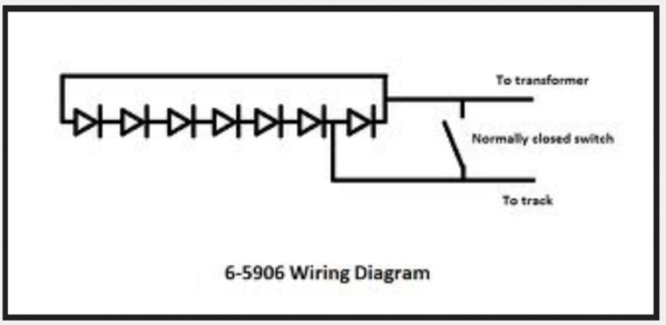
Do you have a link to these "other descriptions"?  The two diagrams you posted are identically and correct.  The 2nd diagram of course just shows the horn scenario.  As the footnotes in the 1st diagram suggest (or that's what I get out of it), if you are willing to live with the AC voltage drop (and rather significant wasted power) from the diodes in normal operation, then you can maintain a relatively constant effective AC voltage when the horn or bell is pressed.

I believe the "last word" has been written on the diode solution/method in that it has been discussed, tried and tested, etc. etc. for decades in dozens of OGR threads.  IMO there's really nothing more to be said.  Extremely cost effective - less than $1 in parts.  If you want to get the job done quickly, cheaply, etc. use the diode method.  1-2-3-done.

Moving on.

There was a somewhat "tedious" discussion here on the issue of DC offset.  Lots of math, integrals, etc..  The point is with semiconductor switches (triacs, transistors) you can be much more power efficient.  The simplest method which I'd call the 20 year old solution would be to go with a triac-based solution.  This would look something like:

z750 controller guts

which are the guts of a MTH Z-750 controller which is triac-based.  That's a heck of a lot of components and it does more than what is asked for by the OP but gives an idea of what's involved.  The component cost is actually trivially small.  Resistor, capacitors, etc. are a few pennies each.  The IC chips shown are maybe 25 cents each.  The triac is maybe 50 cents each.  It's just a lot of parts for a DIY.  Other than a learning exercise I can't imagine anyone doing it this way in 2017.

GRJ posted some nice oscilloscope photos in that thread showing the concept of asymmetrically shifting the chopping point of the AC waveform on the positive and negative cycles to effect a DC offset.

So what I'll call the 10 year old solution is to use transistors (specifically FETs) to implement the asymmetrical chopping.  Much more power efficient than triacs.  My understanding is this is how the more recent MTH Z-controller performs the asymmetrical chopping of positive and negative AC.  In other words this is the replacement to the Z-500 and Z-750 triac design.  But, again, I do not see anyone doing this in 2017.

If doing this today, I'd go with a microcontroller-based design using FETs to chop the waveform.  The microcontroller can be of the $1 or less ilk.  So it's not the cost but rather the need to develop software - not particularly complicated software but probably not something that's floating around in the Arduino world where you "just" need to change a few line of code here and there to adapt it to this application.

In looking at the Z-750 controller picture above, the presence of a single $1 microcontroller chip would whack away dozens of components.

So cutting to the chase.  I don't see the value in developing a circuit to simply insert a DC offset per the OP's specific application of a ZW in conventional-variable voltage DC.  I stand by my statement that it is a design-option which addresses the boost/speed-up issue when the horn/whistle button is pressed.  Again, it is not particularly expensive in component cost but would be a serious assembly effort.

What would interest me is if someone really had the wherewithal to implement a microcontroller-based solution to the conventional-mode controller.  I've stated this before but IMO the triac was the worst-invention-ever for O-gauge AC.  Yes, it performed admirably for decades but in my fantasy world we simply jumped ahead several decades to a microcontroller solution using high-frequency synthesized sinewaves (like the Z4000) rather than low-frequency 60 Hz chopping.  This would be the same technology used today in your home-theater amplifiers where you get hundreds of Watts of PURE sine output in remarkably compact packages for around 10 cents per Watt rather than, say, 10 times that for an O-gauge pure or almost pure AC variable output controller.

Attachments

Images (1)
  • z750 controller guts

So short of the “high-tech” modern solution, forgive me if I over simplify my understanding of what would make this work.  (I’m not terribly fascinated with the wasted voltage in the diode array.)

 A DC offset, or positive or negative will trigger the whistle or bell respectively.   What DC voltage is required for the offset? 

 I have read that a D-Cell battery will trigger a post-war whistle relay. Having not found a schematic on this, I imagine the positive would go to center rail and negative to outside(?)

 If this is the case, will adding a + or - low voltage DC circuit in parallel with the AC track voltage be able to trigger the whistle or bell (or special sounds) on modern equipment? (Signal Sounds, conventional Rail Sounds, Polar Express conductor announcement car, etc).   i.e.: “hot” AC to a rectifier, to a voltage regulator, resistors etc. to get correct voltage, and push buttons to “add” the +/- DC to the AC track voltage in a parallel circuit.   

 Again, I am sure I have over simplified this, but appreciate the education.

 Thanks,

Jim

This is all beyond me. To quote from Get Smart:

Chief: "Did you get that Max?"

Max: "Not all of it Chief."

Chief: "Which part didn't you get?"

Max: "The bit after you said "Now listen carefully!""

I've confirmed what others have written on this Forum - that the whistle button on a PW transformer is no good for a modern locomotive. It just makes the loco speed up incredibly fast. So I followed Lionel's instructions and sourced two Sound Activation Buttons for bell and whistle. It seems it wouldn't hurt to upgrade the wires to something heavier. If the recommendation is to also use a higher amperage diode, then it might have easier just to build my own.

Sound Activation button

Attachments

Images (1)
  • Sound Activation button


That is what will be in the buttons; diodes.    The only thing "wrong" is they are limited in amp carrying capabilities. The wire leading to/from them is possibly  a new limiting factor in your power delivery. Is the wire too small? Compare.

 You likely had it figured right. Every diode eats 1.5v , that explains how many get used. Aways active then removed by button gives boost by eating volts till the button is hit.

You need at least at least 1-2  diodes to get an offes.of 1.5-3v. So add 1-2 (or leave 1-2 to acheive that.)

Thanks.

So is it possible to create a simple 1.5v DC circuit, parallel to and off of the track voltage which would replace the battery,  with button(s) and/or a DPDT switch to reverse polarity to add + and - back to the track voltage?  Or is the issue that the track voltage would have to run through the circuit, therefore it is not that simple?

Thanks

Jim

Jim Harrington posted:
So is it possible to create a simple 1.5v DC circuit, parallel to and off of the track voltage which would replace the battery,  with button(s) and/or a DPDT switch to reverse polarity to add + and - back to the track voltage?

K-Line had an externally powered whistle controller that does exactly what you are proposing here.  The logic is sound, and  the K-Line unit was rated high enough to carry the load longer than a few 1 watt diodes would.

If you have access to a larger HO power supply, like a Lionel 0100, you can experiment with a DPDT switch for polarity and a DPST snap switch to see if it produces the desired whistle/horn activation.

Not exactly that simple. Adding a dc source can be done, but there are some concerns with where the dc comes from; how it might be rectified, phasing. DC from a battery source is a bit simpler as there is total isolation.

The simple way to do it externally is with the diodes as shown, using two strings to get bell and whistle/horn both.

Add Reply

Post

OGR Publishing, Inc., 1310 Eastside Centre Ct, Suite 6, Mountain Home, AR 72653
800-980-OGRR (6477)
www.ogaugerr.com

×
×
×
×
Link copied to your clipboard.
×
×