stan2004 posted:phil gresho posted:Stan: Re: your statement, " This averages to an effective DC offsets and hence there are filters (capacitors) in the offset detection circuitry IN THE ENGINE to smooth out this "chopped DC":
What about 'old'/conventional engines?
If by "old" you mean one that uses some type of electro-mechanical mechanism to detect the presence of a DC offset, then I'd think they might vibrate, buzz or loudly protest to pulsed asymmetrical bipolar pulses. Or, if designed with chopped controllers in mind, I'd think they could be made to simply not respond using some type of mechanical hysteresis.
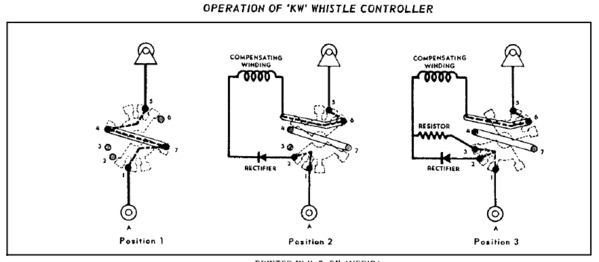
The Lionel whistle control relays don't detect DC, they detect frequency. High inductance relay coil with a shading ring at the end. They will indeed pick up on AC below 40 Hz or so.