I'm planning my first big layout going with Atlas, Gargraves, or Ross Custom Switches and I had a question that I remember struggling with on my layout when I was a kid. 

I inherited some of grandpa's postwar stuff. That included four wired remote switches. I remember them working well unless they were connected to one another. They would buzz and act funny (throw themselves) and get hot. The trains also didn't seem to be into this. I was 11 so I didn't know if the streams were crossed or if you just weren't supposed to do that but I remember having to put track between the switches. I don't know where those pieces are so I can't replicate it but there have been a number of spots on my layout design where one switch will run right into another. Is this a common issue? Should I have small pieces of track between switches? I plan on using Legacy and DCS for the most part. I'm not going to convert the postwar turbine I have so I'll only run conventional on special occasion. I wanted to have the ability to use command control to throw switches because some switches are hiding for staging and others would just be tricky to reach. 


Original Post

Replies sorted oldest to newest

Many turn out tracks (switches) use control rails that need to be isolated with plastic/fiber track pins. This is all very well laid out in the user manuals and service guides:

See printed pages 26-28 for the O22 and 1122 style:

https://ogrforum.ogaugerr.com/...sories%20%201954.pdf

Reiterated in the modern tubular switches:

https://www.lionelsupport.com/...ents/70-5121-250.pdf

https://www.lionelsupport.com/...ents/71-4062-250.pdf

Fastrack switches have the control rails embedded and internally insulated. No need for special pins.

Bottom line, there isn't an electrical incompatibility with placing switches together provided you accommodate the requisite fiber pins for those switches that have control rails at the track junction.

Also, your experience with the 1122 style switches heating up and throwing themselves clearly are symptoms of not having the control rails insulated with the fiber/plastic pins. As such, they are continually activated , generate heat, and can actually melt/burn to the point of self-destruction.  This can also happen if you use an improper throw switch, it gets stuck, or you park a train on the control rail.

That explains it. I'm glad I didn't burn the layout/my parents house down.

But anyways, I understand now. I definitely didn't have insulated pins or anything. That's very good to know. I started with manual switches and never needed to mess with that. There weren't manuals in the box for those old remote switches.

Thanks for the help!!! Sorry for such a simple question. It's weird coming back into this almost 20 years later and seeing how much as changed and trying to remember what I did as a kid.

Also weird to realize it's almost 20 years ago haha

On Lionel tubular switches one rail in each direction is isolated to create an automatic throw if the train enters the switch in the wrong direction.  These isolated rail sections require an insulated pin to keep them isolated from the grounded outer rail.  The condition that you describe sounds like the insulated pins not in the proper place perhaps grounding the isolated rail or connecting an isolated rail from two switches together, causing them to fight each other.  This can get confusing and if connecting switches together, the connections of the isolated rails needs to be planned.  I have often torn apart switch areas to change the location of or add a fiber pin.

On the question of using short sections between switches, this is more a mechanical than electrical issue.  There are situations in connecting two switches, where there would be a fiber pin in both ground rails.   This leaves only one (center pin) physical connection between switches, not enough for a floor layout, though maybe ok on a table with screwed down track.  I build a lot of floor layouts and I often use short sections between switches.  This has two benefits.  One is that you can usually get two pins in every connection.  Secondly, trains that dont like switches (I have a group) often run better through the switch with a "straight approach".  I find that I often need to make a track power and ground connection to these short sections between switches.

Sometimes there just is not room for this approach.

Bill


Bill,

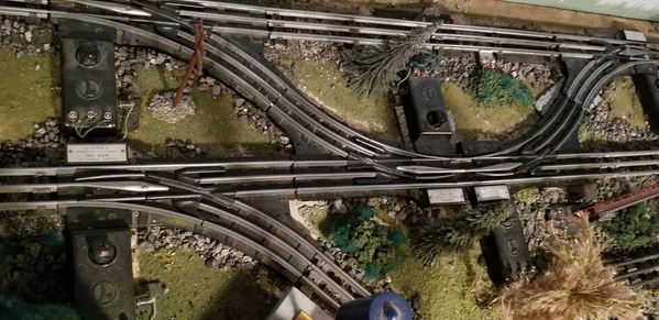
I have Postwar 0 Gauge remote control switches (022 switches) some of which are right up against each other at an interchange between the 2 independently powered main lines. See photo below;

20181127_081454

When those 60 to 70 year old switches are properly refurbished and fiber pins are properly inserted between them as mentioned by bmoran4, they work flawlessly.

Arnold

Attachments

Images (1)
  • 20181127_081454

It sounds like I was a few fiber pins short of being ok. I remember the switches working very well when they were alone. But I could never figure out what the deal was when they were used as a crossover. 

This will be a permanent tabletop layout with s things screwed down and connections soldered where necessary. I hope I'm not being too confident by saying that I wasn't thinking much about connection issues between track pieces. I am concerned about sending dockside switchers, flickering load torpedo and slag cars, and other small switchers over all these switches. 

What engines are normally in the group that doesn't like switches? My experience is running conventional 0-27 and they basically blasted through everything.

Add Reply

Post
The Track Planning and Layout Design Forum is sponsored by

AN OGR FORUM CHARTER SPONSOR

OGR Publishing, Inc., 1310 Eastside Centre Ct, Suite 6, Mountain Home, AR 72653
800-980-OGRR (6477)
www.ogaugerr.com

×
×
×
×
Link copied to your clipboard.
×
×