Oh... that's so good! So, here's the deal. I could get this or get the DCS/Legacy control systems the layout needs... I can't get both... at least not this year.


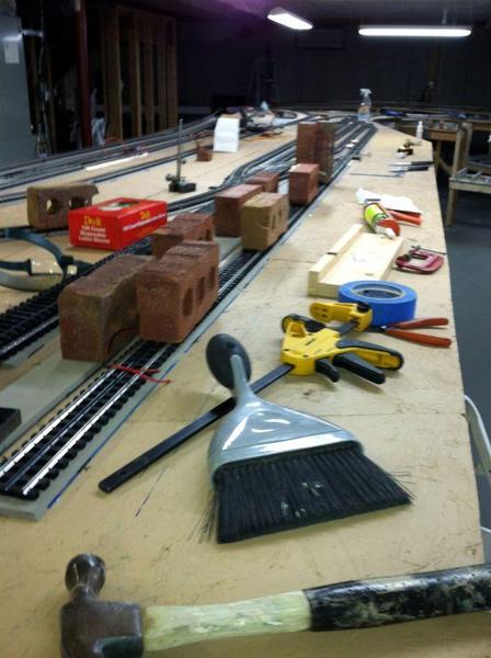
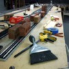
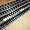
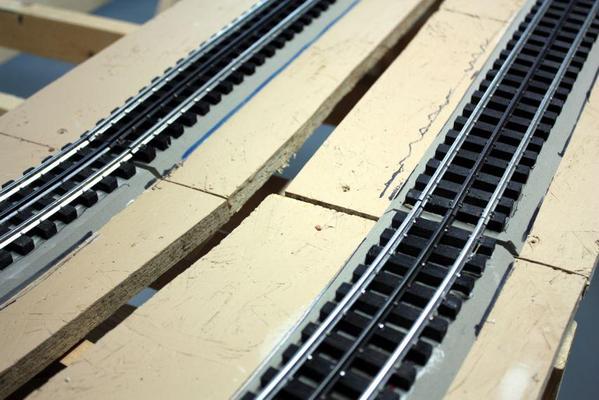
I finished the gluing today, worked for close to five hours. Much to my horror, some of the new Loctite glue was gluing to the tracks great, but was releasing from the Flexibed. Judicious use of super-glue got things under control, but it freaked me out. I went back to using the DAP adhesive.


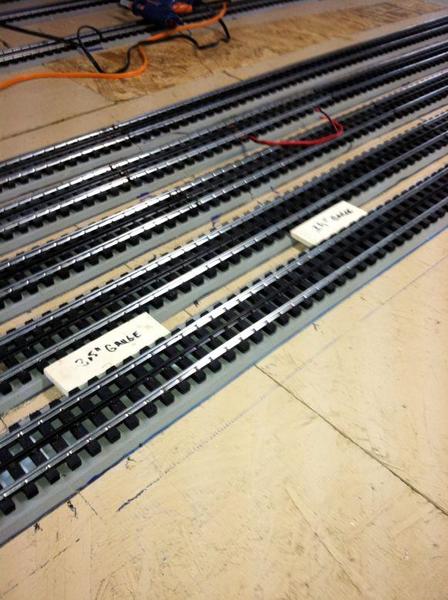
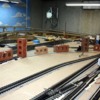
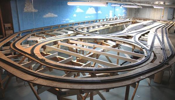
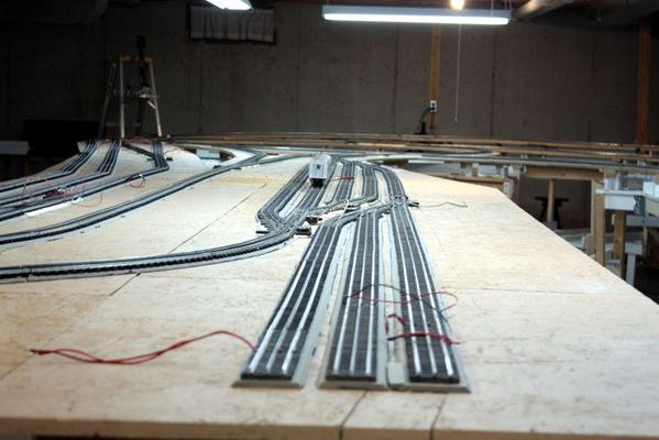
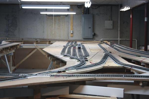
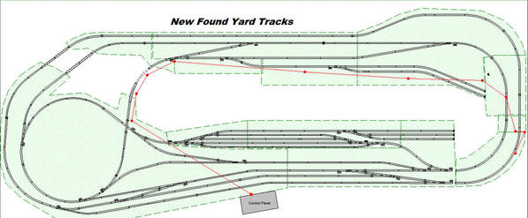
I made a couple of wood gauges to properly space the yard tracks to 3.5 center-to-center, and I used a string line to set up the long run from the outside yard switch to the engine service tracks. Everything came out pretty well and the last "s" curve piece that connects the yard to the inner mainline at the swing-gate pretty much dropped in with no correction. All in all, the track really fit well and other that problems with the very first tracks we laid down, it went according to the RRTrack drawing.


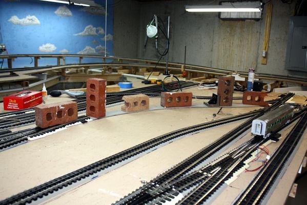
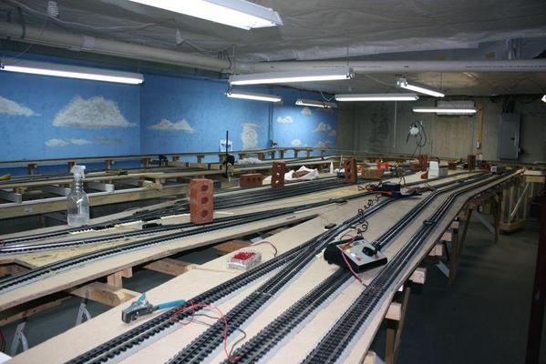
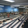
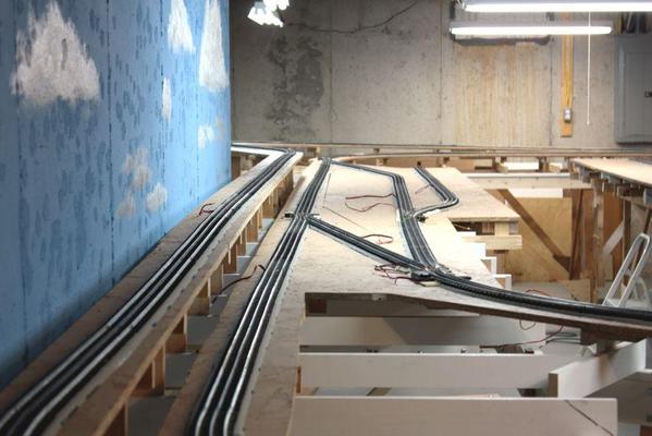
I'm letting all of tonight's work cure for 24 hours, then I'll clean everything up for another overall status shot. Then it will be on to wiring.


Gluing down the tracks 10


Gluing down the tracks 9


Gluing down the tracks 8


Gluing down the tracks 7

Attachments

Images (4)
  • Gluing down the tracks 10
  • Gluing down the tracks 9
  • Gluing down the tracks 8
  • Gluing down the tracks 7

Trainman,


Before you go to the trouble of taping the backside of your control panel think about this.  This idea was mentioned on the forum several years ago.  Use your favorite software package to layout your track plan.  Add on the lettering and other ID info you want.   This takes care of the visible side of the panel.  If you reflect the image right-to-left will take care of the backside.  You can add all the necessary notations for wiring and drilling holes.


When you have completed the masters drawings go to a graphics print shop have them print the front and back on poster-sized paper.  Hopefully, they can register the originals and do it two-sided. 


You can use spray glue to sandwich the plexiglass and prints together.


Jan

I put all the stuff away, found the bag of extra ties that I was unable to find for weeks, and took some final pictures of the track laying. I also stopped by the tracks of the Norfolk-Southern RR to take a picture of rail to get the right color for the rail painting, and picked up a few pieces of real railroad ballast to measure it and then scale it down to 1:48. I want to know just how big (or little) the ballast particle size should be to look right. A little obsessive you say? Yes!


I inserted some of the extra ties in gaps between cut rails. Sometimes the cut rails came out leaving a tie missing. Inserting them in afterwards closed up the gaps.


While this looks very similar to the last status portrait, everything is tied down and ship shape. Everything is as straight as I could get it. No perfect, but close enough for O'gauge. There's one track right in the center that's just touching the one opening in the platform, but instead of using more OSB I'm just going to fill it with Styrofoam since it's not going to be load bearing. I'm just tired of screwing in OSB, and having the screw points protrude through the top, and then have to grind them off with the Dremel. That phase of this project is over.


 Progress Shot Glue Complete


Here's a close up of hinge-side track joint for the swing-gate. The trains roll over the gap without a whimper.


 Gluing Complete 5


The yard tracks came out nice and straight, but if you look closely, there seems to be a hump in the middle of the runs. It's a panel joint that didn't come out dead flat. It's only in the yard, is very slight and shouldn't cause any operational problems.


 Gluing Complete 4..


Here's the back side track. It came out nicely.


 Gluing Complete 2


And here's another view of the yard from the left end. You can plainly see the roadbed just coming to the edge of that opening. Can't wait to get this thing wired up and have some trains running. My MicroMark heavy-duty Styrofoam cutter arrived today. Can't wait to try it out on some blocks of the stuff I have lying around. What problems are there with fumes with something like this? I really can't ventilate the basement very well.


Gluing Complete 3

Attachments

Images (5)
  • Progress Shot Glue Complete
  • Gluing Complete 5
  • Gluing Complete 4..
  • Gluing Complete 2
  • Gluing Complete 3

Cutting in the garage makes sense. I do a lot of the heavy spray painting there too. That is as long as I remove the cars. I painted a freezer with Appliance paint from a rattle can, but didn't take my Acura out of the garage. I was halfway through when my wife stuck her neck into the garage seeing the fog and said, "Shouldn't you have taken the car out of the garage?" The answer was YES! And she was too late. Even though I had the door wide open the car got a fine overspray all over it. It was an epoxy-bearing paint and was a pain in the butt to get off. It got all over the windshield, which I cleaned off. But during a rain I turned on the wipers. They were still coated with dried paint which then abraded the glass and left radial streaks that are there to this day.


To get the spray off the car, the car wash suggested clay. It's a clay that the car restorers use to put a final polish on the surface. It took hours and lots of elbow grease, but I restored the car back to original shine (except for the windshield.) I learned a lesson that day... the hard way. It's said that good judgement is the result of experience which is the result of bad judgement.


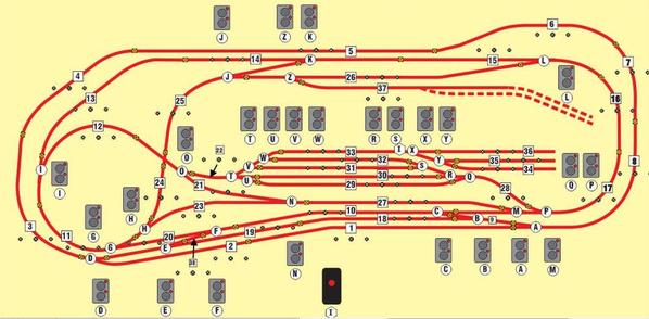
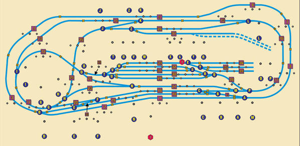
Taking my reader's advice, I redesigned the graphic for the control panel specifically so it can be printed commercially. Since I wouldn't be using masking tape to lay it out, I didn't have to worry about having curves; therefore, I changed the display on RRTrack to a single line, made a screen capture of it and then traced over the image in CorelDraw with a 4mm line. I thought about using a white background, but felt that the spray adhesive may leave a tint that would be objectionable. So I'm using a light yellow which would neutralize the tint (I hope).


I then changed the scheme to place the switch controllers somewhat near the switch images on the track plan. Here's what that now looks like. The dotted line is a future expansion leading to the coal mine tipple. There should be room on the panel for more stuff too.


New Panel Design


I think it will be easier to operate the layout when you have to line up 6 or 7 switches to make a move. Let me know what you think. The image I give to Kinkos (or whomever) will not contain the images of the switch controllers, but the small black circles are going to stay. The larger, middle circle is the hole location and size for the DPDT switches for cab control, and the smaller flanking circles are for the lights that indicate which transformer throttle has the track. If I go digital, I will not need all these block switches since DCS doesn't like passing a signal through this many switches, but I will still need them for the yard tracks which need to be de-energized most of the time.


I've also been thinking about another way to get power to the swing gate without running leads all the way around the layout after crossing the middle bridge. I was thinking about getting a set of pickup rollers with the springs and all. Then mounting the roller on the door side and brass contact plates on the jamb side. When the gate rolls closed, the rollers will glide into position and make contact with the two brass power connectors. The microswitch which controls the power relay would also be in this area and would shut power off to the bridge and approaches to both sides far enough away so any train highballing to dead-man's gulch would be de-energized in time to stop the train. Using rollers would give a sliding contact that would be spring-loaded to maintain contact. Should work... right?


Clem, how do you energize your gate?


Attachments

Images (1)
  • New Panel Design

Good morning Trainman


I just run jumper wires from the track on the hinged side to the track on the gate. This powers the gate track all the time. Train can't get to it when open. Leave a little extra wire and keep it closer to hinge side. I also have switches and lighted buildings on my gate. Basically I just treat the gate as another module. 


Clem

That would work for me except that the hinge side is away from the transformer, and the only way around is across the bridge in the middle of the layout adding about 25 feet of wiring to reach the bridge. Building a contact system would reduce this about 15 feet total. I could have put the hinge on the transformer side, but it would have been a disaster getting through the darn thing.


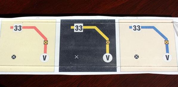
On another subject: I printed out three color schemes for the control panel using the "stick it to the back of the plexi" scheme. I sprayed it with 3M 77 and stuck it to a piece of scrap plexi. Clearly, the black background...which is much cooler... looks the worse since the spray glue shows up. The lighter backgrounds look better and the tan with the blue is the best. I'm going to change the background color for the text because the spray glue discolor the white areas.


 Graphics Test 2


Now all I have to is change the scheme and send it off to Kinkos. I hope the adhesive doesn't let go with age... it probably will. Replacing it would be ridiculous since all the switches and lights would be wired ON TOP of the graphic...oh well.

Attachments

Images (1)
  • Graphics Test 2

Thanks! And thanks for the heads up. What's the electrode made out of? If it's carbon, I can understand why it's so fragile. I haven't even unwrapped it yet.


Here's the re-colored control panel design. Since I'm doing all the graphics on the computer I embellished it a bit like drop shadows under block numbers.


Panel Graphic - Production


Notice that the pictorials of the switch controllers are gone. Only the crosshairs for the drill operation is on the graphics. The diameters are equal to the drill diameter so any evidence of the black circle should be covered by the lights or switches. This is the image that will be printed full-size.

Attachments

Images (1)
  • Panel Graphic - Production

Thanks Jim! I'm sure we're going to need them especially since my grandson really wants to try it out.


When I made the first control panel 13 years ago while in Germany, I attempted to drill the acrylic with a standard jobbers drill with very touchy results. A standard 118º drill tip grabs acrylic on the way out and tends to crack the material. It's very hard to control. A drill for plastic has a sharp, 60º tip angle and has negative rake installed at the cutting edge. You do this by grinding a small flat at the cutting edge on the flute side. This is similar to a drill for brass since that tends to grab also. The negative rake results in a scrapping action rather than cutting as with a regular bit.


I looked up prices to buy these drills and, with shipping, would have cost me another $35. Since the components I'm using are German, they have metric-sized threads. I have a nice set of metric drills so I decided to try my hand at re-shaping the tip. I have a very old, but very nice Dayton bench grinder and, as an old metal shop teacher, have no trouble hand sharpening drill bits. I even taught teenagers how to do it.


The plan worked. The reground drills cuts the plastic smoothly without grabbing upon exit.


So I have a design, I have plastic, and I have the tools. Let's make a control panel.

Last edited by Trainman2001

No... you said it perfectly. What you don't understand is what is shown in this diagram. Getting power to that end of the layout entails crossing over a bridge and coming at it from the other end. If I use a contact system on the door opening section (the left side on this drawing), I could greatly reduce my wiring runs to that end of the layout. Then I could use your idea only coming at it from the front, not the back.


The wire is shown in red. Remember, the entire middle is open so wires can't cross there.


Wiring Challenge

Attachments

Images (1)
  • Wiring Challenge

Drawing on a computer is like anything else. You start simple and build on it. There are programs like Visio by Microsoft that's called "Drawing for Dummies". It very easy to learn. Coreldraw is much more sophisticated and therefore takes much more time to learn. I am still learning things on it. RRTrack, on the other hand, while it is technically a drawing program, lays track really well, but is a terrible graphics program. It is 3D capable, but limited. You can elevate something off the platform base and you can extrude an object to a thickness, but you can't then tip that object relative to the base.


For the ultimate 3D experience, download a free copy of SketchUp and start having fun. It's the most clever, powerful drawing program for free in the world. They have many free video tutorials to learn how to do most everything and it's fun.


I did some checking and to have the poster-sized graphics printed by Kinkos would cost upwards of a hundred bucks, so Plan B is now in effect. I printed the whole thing tiled over multiple pieces of paper which I will carefully cut and put together and then adhere the whole thing to the back of the acrylic. If I do this carefully, the seams should be unobtrusive (not invisible, just not to noticeable). All of the electrical hardware fastened through the panel will keep most of the sheets from delaminating. Tomorrow I'll give it a try. This way it cost the price of the ink in my printer.

Trainman, My 2 cents on the gate issue:

I have to agree with Clem, its only another 40 or so feet.  wire is not that expensive. at compared to what contacts and future issues with them are going to cost.  


on my layout, to save wire, I buils a raised trough on the floor, about 1.5 inches high with 5/8 OSB on top and plywood on each side as a "Ramp" so you wouldnt trip over it .  The top screws on for easy removal to add wires.   In the future, you will have WAY more than two wires at that end of the layout

Ryan

Good morning Trainman


I purchased RR track, had a computer geek install Windows and RR. Took him awhile to do that.I played around with it and never could figure out how to do anything, I did notice my computer was slower. I am on a four year old Mac book,with latest operating system. After trying for three weeks I gave up and drew my railroad expansion in one afternoon with pencil and paper and ERASER. I was in over my head. I really am computer challenged. touched a computer for the first time four years ago, the way I see it this is a different language and non of the buttons mean what they say. Took me over thirty minutes just to type this. That is why I don't post much. However my little railroad expansion is doing well. Thanks for listening. Got to get back to the railroad, have to be done by April 20th big 2 day open house for the village Railroad Days weekend.

Clem   

Good points! So I'll run the wires around from the far end and avoid the complication of the contacts. But, there's still the shut off circuit. As I planned it would be at the latch end therefore, making more long wire runs. I could actuate the microswitch from the hinge end and have all the circuitry there. But then there's one more wrinkle. I also wanted to shut the power off one block on either side of the gate, which brings the latch end back into the equation. I may scrap the whole interlock concept and just pay attention to when the gate is open. It's not actually trains on the gate that I'm worried about, it's trains approaching it. Nothing's ever easy...


Clem, you've got to get a good teacher. Computing is not hard... it's just different. I taught myself all I know about computers when I was 40. That includes learning how to touch type. I couldn't even type my name in college and had all my papers typed by someone else. I learned computing out of necessity... I was sharing a secretary with my boss and having nothing done by her. When offered a chance to get time on the mainframe to produce my own work, I jumped at it. Subsequently, I became the first manager at my next company to produce his own documents directly on the PC. At the same time, I started to learn how to produce my own graphics. It made me very productive and much more powerful. I had my admin staff do much higher level stuff, as well as producing more substantial production things.


Computing multiplies our intellectual powers in much the same way as the steam engine multiplied our physical powers. The analogy holds true on many levels. Not only does the computer allow us to do some things more quickly, it enables us to do many things that were either extremely difficult or impossible without them. Try building the Panama Canal without the steam shovel... you could do it, but it would have taken generations, not years.


Just for fun, look up SketchUp on Google and see what it does, then we'll talk about this some more.


I woke up this morning wondering how I'm going to fasten 12 pieces of paper together so I can then glue them to the back of the acrylic sheet. I can't overlap them as I usually do when putting together a multi-page image since the overlaps will cause gluing problems. They'll all have to be butted together so they are flat after assembly. I have a big paper cutter which I'm going to use to make the cuts since they have to be dead straight or the seams will look poorly. Once they're all adhered to the plastic, the tape holding the seams isn't needed any longer so I may remove it. I will also spray the back and front of the image with fixative to stabilize the image, seal the ink, make it more moisture resistant, and give the paper more body. This whole thing is quite an experiment that many others can use going forward.


I'll document all this in pictures and post tonight.

Had sort of a milestone today! After some more prodding by #1 grandson, we decided to fully power one loop, the outer one, and run a train. He promised that we'd be back to work once we did this. It meant running jumpers from one insulated block to another assuring that every block was captured. We did midway up the grade yesterday and I finished today. I pulled out another engine, the Lima Center Cab, since it was a two-truck engine with only two motors unlike the Veranda which is a pain in the butt to re-rail if something goes awry and it has four motors.


I put the power to it after making the last connection and got 11 volts, but a huge amperage, and then the overload light started blinking. I started troubleshooting and one hour later had a running engine. The problem was we switched which was hot and ground about halfway around. The transformer doesn't like that. 


Now you ask, "How the heck does an experienced model railroader who's been around circuitry for 55 years make a bone-headed mistake like that?"


Let me explain. I was using cable that was from my German layout. Some of the cable was two conductor with blue and brown conductors. The other cable was a three-conductor with blue, brown and green/yellow striped. The first cable we attached was the three conductor and I used the blue for hot and the green as common. But shortly after we started we switched to a 2-conductor and the brown became hot and the blue ground. We even had one where the blue was ground on one end and the green at the other. In other words, it wasn't even conducting. I was using the black 2 position barrier strips with a buss bar on one side since we needed to pass the lines through each block while tying the block leads to each strip. It took every strip I had to make this run.
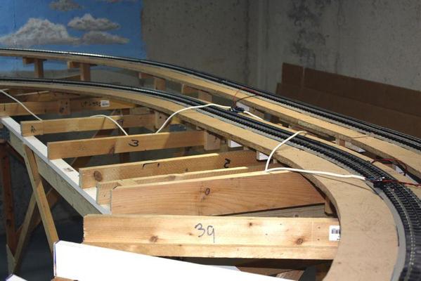
 

Jerrry Rigged Running 1


The longest leads I had are 8 foot. That's not a coincidence. I had to make a junction at every subroadbed panel in Germany so the railroad could be taken apart and moved stateside. So in addition to making a place to tie each block into the main, I had to splice together a whole lot of cables just to stretch around the room.


I videoed this maiden run. It's plenty boring! Just one engine and a passenger car going around in a circle... a great big circle. At 17 volts it took 45 seconds to complete a loop. Since nothing else is powered on layout (including all the switches) for the moment this is all the running that's going to happen. Here's links to the two videos.


http://www.youtube.com/watch?v=cOKu0-4pwmE

http://www.youtube.com/watch?v=CeZAbnJ-3RQ


On the second video I ran the engine at a slower speed and filmed it transitioning the swing gate. I'm a little concerned about one rail on the opening side that needs some J-B Weld to stabilize since the spikes are a bit loose and it needs to be a bit smoother on transition. But as you can see, it runs nicely through it. Next I'll bring out a big steamer and see how that works.


What was gratifying—beside having a hundred feet of track that didn't have any operational problems—was the way both my Veranda and the Lima Center-cab came out of their boxes after almost 4 years and ran like tops. I hope my 3rd Rail stuff does the same. I really missed seeing them around!


I also finished stripping all the old control panels, and started building the frame for the new one. Here's the two side frames showing the angle that the panel's going to sit.
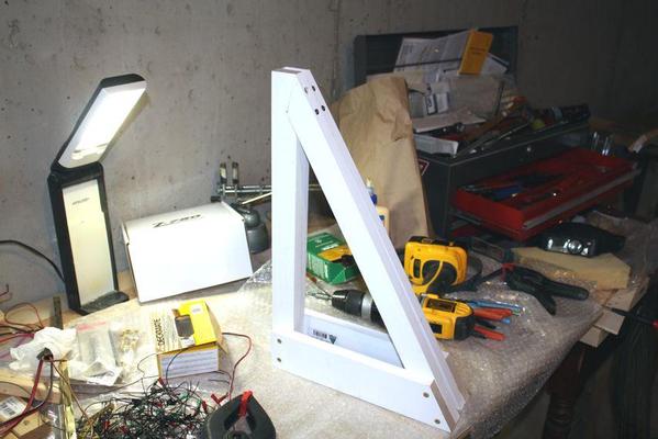
 

Control Panel Frame 1


I also mounted my old transformer stand. I needed to splice on some added length to the support bars since this layout is wider than the old one. It's tied into front and rear L-girders. That rats nest wiring IS NOT the way it's going to look when I'm done. The white 2X3 serves two purposes. It fills out that area where the track was perilously close to the edge and adds a attachment surface for the panel that's to come mounted on the near side of the transformer transformer stand.


 Transformer Mount 2

 This week between work assignments I'll finish up the control panel structure and start building the control system. I want to wire it for cab-control AND DCS/Legacy. I haven't quite figured out how to do this without creating parallel wiring systems and 2,000 feet of wire. As it is, to do star wired cab control will take close to 600 feet of two-conductor twisted pair wire. It's all part of making a layout BIGGER.


Attachments

Images (3)
  • Control Panel Frame 1
  • Jerrry Rigged Running 1
  • Transformer Mount 2

Add Reply

Post
The Track Planning and Layout Design Forum is sponsored by

AN OGR FORUM CHARTER SPONSOR

OGR Publishing, Inc., 1310 Eastside Centre Ct, Suite 6, Mountain Home, AR 72653
800-980-OGRR (6477)
www.ogaugerr.com

×
×
×
×
Link copied to your clipboard.
×
×