
Yep, since it's a yard track and it'll be slow speed operation with anything going down that line, I figured I'd shoot the dice.  In order to keep the curves at O72 or larger on all the tracks, that's where the track ended up.  I could have done even more ripping up to move it a little, but I decided it wasn't worth the trouble.

I like your way of thinking John, once its down, move it as little as possible!

20210910_175238


John, viewing your project sure gives me space and track envy.    Great fun to watch your project progress.   Thanks for sharing!   Curiosity has a hold on me; please explain the push out the far left side of the yard track.   Looks interesting!  Thanks!    

I want to give you a big shoutout for sharing your expertise, help and the numerous responses you provide to so many forum topics post.   A personal "thank you" for your help and parts list you provided me for installing the Mars Simulator on my "Northland" business car project.   I have all the parts and it's scheduled for a winter instillation.    Where you find the time to work on your own layout is truly a mystery to me!

Cheers, Dave

Last edited by darlander

The track is done!  Of course, there's mounting the ground throws, wiring the power, etc., but the cutting and sanding is out of the way!  My test car rolls smoothly though all the paths to the ten tracks, so it's on to the next part of the installation.

20210912_142333

I think there's more track in this yard as I had in my previous layout!   Counting the paths over the switches, there's over 170 feet of track for the yard and the leads.  If I don't mind parking on the bridge on the separate tracks, 138 feet of that is usable yard.  If I insist that all the cars be on the main yard platform and not obstruct bridge opening, then it's 120 feet of yard space.

Attachments

Images (1)
  • 20210912_142333
@darlander posted:

John, viewing your project sure gives me pace and track envy.    Great fun to watch your project progress.   Thanks for sharing!   Curiosity has a hold on me; please explain the push out the far left side of the yard track.   Looks interesting!  Thanks!    

I want to give you a big shoutout for sharing your expertise, help and the numerous responses you provide to so many forum topics post.   A personal "thank you" for your help and parts list you provided me for installing the Mars Simulator on my "Northland" business car project.   I have all the parts and it's scheduled for a winter instillation.    Where you find the time to work on your own layout is truly a mystery to me!

Cheers, Dave

Thanks Dave.

The "nub" on the side is to allow the possibility of sticking a switch in the last yard track and building out.  Not in my current plans, but you never know.

Thanks guys, I'm really looking forward to actually using this new space!  Got my ground throws mounted, so I just need to wire power to everything and I'm ready to rock-n-roll!   Naturally, the power promises to be a PITA to get to the yard, I don't want to run it across the floor, so I have to take the long way around to get it over there.  I also have to come up with a little switch panel with ten switches to control the yard tracks individually.  I'm hoping there's at least light at the end of the tunnel that isn't an oncoming train.

@RSJB18 posted:

How are you planning to power the tracks over the liftout? That's a lot of track to wire

Well, the bridge and the leads on the main platform will be powered from a couple of switches on the fascia.  Each of the two yard leads is separately powered.  For the actual yard platform, I'll run a single power feed over there to a 10 position switch panel.  So, there will only be a couple of wires since I don't have any switch wiring.  I'm actually thinking that maybe I can rig some spring contacts so it comes across the bridge, another part of my "thinking".

@RSJB18 posted:

now I see why you used ground throws too.

Yep, imagine all that wiring.   Besides, yard operations are going to be done with you standing right there, so it's easier and quicker just to flip a couple of levers on the switches than fumble with the remote.


20210911_203307


You probably have already resolved the 1/4 inch transition, but if you are still looking for suggestions:  A deck of plastic playing cards cut into 1/2 strips and stacked, used as shim, etc.   They are as wide as the ties and would be easy to produce smooth transition pillars.  You would probably only need to support the track every three or four inches.   I assume you will be adding ballast and that would fill in the gaps, add support and cover any card pillars under the track.   My $0.02 worth!

Cheers, Dave

Last edited by darlander

John,

If no one but you is likely to be going in the back, why not run the wiring on the floor? Just put it in a wire cover like this one. You can find these on line or at Staples. They do a good job of reducing the trip hazard. You can find them in a variety of sizes and styles. Not very expensive.

Chris

LVHR

Attachments

Images (1)
  • mceclip0
@darlander posted:

You probably have already resolved the 1/4 inch transition, but if you are still looking for suggestions:  A deck of plastic playing cards cut into 1/2 strips and stacked, used as shim, etc.   They are as wide as the ties and would be easy to produce smooth transition pillars.  You would probably only need to support the track every three or four inches.   I assume you will be adding ballast and that would fill in the gaps, add support and cover any card pillars under the track.   My $0.02 worth!

Well, I may be anal, but I do want a smooth ramp under the track and I'd like it to look OK until I get around to ballasting.  I know I can just shim it up , but I'd like something "neater".  I'm still mulling over ideas.

@lehighline posted:

If no one but you is likely to be going in the back, why not run the wiring on the floor? Just put it in a wire cover like this one. You can find these on line or at Staples. They do a good job of reducing the trip hazard. You can find them in a variety of sizes and styles. Not very expensive.

I know about those, and I actually have several lengths of it around here somewhere.  I'm thinking since I only have a couple of power wires over, I may go with spring contacts on the bridge itself to bring the power over.  I really don't want anything on the floor there if I can avoid it.

John,

You are going to have juice on the lift up so why not feed off of that source?

Maybe consider a pair of spring wipers against a pair of pads then onto an MTH 12 port terminal strip then feed each track through a toggle.

Guessin' you are going to need to select  which track the cross over center rail will be tied into.

You could also use the pair of square brass dowels.  That is how I feed my lift out bridges.  Friends have poo-pooed it saying it will fail but it has been working steady for six years now.

Last edited by Tom Tee

To run power across an opening I use a pair of brass pins to connect both + & - :

lift out overall 009


For powering just the lift out,  I solder leads on the male and the female square dowels connecting to the rail and supply.  Although questioned by some I have yet to have an power interruption in many years:

IMG_8657

The pin east pin is power by the near rail the west pin is powered by the far rail.  The switches deactivate the powered rail when the bridge is up.

IMG_8658

Attachments

Images (3)
  • IMG_8657
  • IMG_8658
  • lift out overall 009

Yes, the same pins style.  I have used them on many jobs over the years.

If you are not comfortable with friction fit style simply use a two pole Anderson power pole connectors.

Available at any Ham Radio store or I have open stock in all colors plus the special Power Pole crimper.

IMG_6418You would only need two of these.  Like one black and one red.

Attachments

Images (1)
  • IMG_6418
Last edited by Tom Tee

Love the new yard.  Quick question that I assume I know the answer to but I'll ask any way.  I don't see any uncoupling section of track in your yard.  Does that mean all your locos have elecrocouplers?  Or is there another reason?  Last time I built a layout electrocouplers did not exist so I had an uncoupler at the top of each row in the yard.  As I contemplate a new layout I'm wondering if there is a need for them anyomore.

Well, there is actually a use for them, and I am contemplating that addition.  I would likely retrofit the yard with this kind of uncoupling, probably right at the entrance of each of the yard tracks.  This would allow backing a larger consist than will fit on one track and dropping off a dozen or so cars on that track and then selecting another track for the remainder of the cars.

Hiding the Uncoupling Magnet in Your Yard Tracks

I figure to get a little mileage on the yard before I make the decision, not to mention I have to find the time to do the mods.

@romiller49 posted:

GRJ, why not just use a separate brick mounted under the yard to power it. Since the lift is part of the main line with hinges, power to that is supplied with a wire or wires from the main attached to it.

How would I get the power feed from the TIU so that DCS stuff runs over there?  The object of the exercise is to be able to run TMCC/Legacy and DCS in the yard.

John,

How about something like this? Solder a lead to the straight side and drill a mounting hole. Then edge mount on both the lift bridge and the yard.  Hide them under the tracks. Set one facing up and the mate facing down. You would need 40 of them. I found them in Digi-Key. Not certain of their size.


Chris

LVHR

Attachments

Images (1)
  • mceclip0

Got my PoGo contacts in and installed the connections on the freight yard bridge.  I repurposed some contacts from MTH engines for the bridge section.

Freight Yard Bridge Contacts N1

The PoGo contacts are on the fixed freight yard side, they go down through the wood and the gap and wires are soldered below the layer to feed the freight yard.  I had to relieve spots for the solder connections and screws as these two sections go right together with minimal space between them, less than .05".

Freight Yard Bridge Contacts N2

The PoGo pins are spring loaded contacts for testing, they work well to make the connections.  Each contact is rated at 5 amps, and I'll have two in parallel for power and ground, should be more than enough capacity for a freight yard!

Attachments

Images (3)
  • mceclip0
  • Freight Yard Bridge Contacts N2
  • Freight Yard Bridge Contacts N1
Last edited by gunrunnerjohn
@GP Ogauger posted:

John,

Looks fantastic! I am starting on a new layout and was considering the DZ2500 switches and was wondering if you resolved the issues that you were having?

Thanks.  I have resolved the issues with the DZ-2500's. at least for now.  Most of the issues revolve around springs as it turns out.  The one issue with the serial data was figured out, and I'm currently using the Z-Stuff Data Driver until I do the fix for the CSM2 power sequencing.

If I had it to do over again, I'd go with the Tortoise switch machines, bulletproof and a once and done deal.  However, they're a lot more work to install initially.  My lazy streak went with the DZ-2500 because they were command and they were easy to install.

@amtrack5899 posted:

You may want to consider manual throws where possible.   You could even  want to use the DZ1000 that has a manual throw on the switch motor then wire it later if needed.

My whole yard is manual throws.  As far as the mainline, I have a route set up that I can clear the entire mainline and set all the switches right with two buttons, I'm not ready to give that up.  Also, many switches are out of reach anyway.

I'm not changing at this stage, I was just saying if I knew then what I know now, I'd have given the Tortoise switch motors more thought.

The yard is done! Time for a party!  Got my switch panel installed, wired all the tracks, and tested all the routes and switching.

One little glitch surfaced that I overlooked when laying track.  The Ross #202 yard switches that I used I "thought" I ordered pre-wired, but in looking at my invoice, I got the plain bare switch.  So, power was not carried through the switch.  In truth, that was probably a good thing in retrospect, I got to decide how the crossover to the next track was powered.  However, I conveniently forgot about power until I was testing and noticed that the power stopped as the switches!   That little oversight was corrected and now all is well.

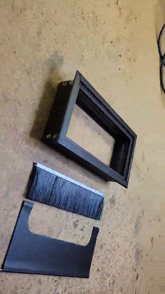
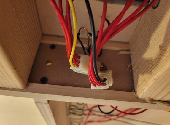
I embedded a little lighted push-button toggle panel into the yard to power each track individually.  Given my track record with switches lately, I added connectors at the panel so I can remove it if necessary to replace a switch!

20210924_09472220210924_094748

Attachments

Images (2)
  • 20210924_094722
  • 20210924_094748

I'm going to just put a "bumper" on the wall at the end, no sense in losing a couple inches of yard for a bumper.   I want to find a piece of black rubber that I'll just stick on the wall.  Above it, I'm putting track numbers so you can see what track you're dealing with.

I don't know about easier to wire for the lighted switches, but they were easier to fit into that panel.

I found that panel on Amazon, it's actually a desk bezel for passing wiring through.  I took the trapdoor and brush assembly out and tossed them.  There was a convenient slot near the top to slide in my fiberglass panel with the switches mounted, job done.

Antrader 160mm Length Black Metal Rectangle Wire Cable Grommet Hole Cover for Computer Desk Table (Black)

Attachments

Images (2)
  • mceclip0
  • mceclip1

Awesome yard & control panel! I wish I had room for half of that.

You may have thought of adding a photo backdrop, but if you haven't, I created a very quick possible example. It would be a fairly easy, inexpensive addition. See attached. Of course you may have something else in mind or nothing at all.

Attachments

Images (1)
  • JOHN'S YARD
@ironman1 posted:

Awesome yard & control panel! I wish I had room for half of that.

You may have thought of adding a photo backdrop, but if you haven't, I created a very quick possible example. It would be a fairly easy, inexpensive addition. See attached. Of course you may have something else in mind or nothing at all.

Nice background, looks like it belongs! I'm having trouble breathing just looking at it.

Tom

Hi Tom,

If you search the internet for "train yard pics" & "industrial landscape", you'll find the original images I combined.

Thanks for the interest,

Joe

P.S. The scary background is something I created from a 1936 animated movie, "Max Fleischer's Play Safe". It was a favorite of mine as a kid. Back in the 60's it would play once in a while during Saturday early morning cartoons.

I shared the movie with my grandson when he was about a year old & it became a favorite of his. So I did a bunch of screen grabs while playing the movie. Then created it in Photoshop. It's now a background on my layout.

@ironman1 posted:

Awesome yard & control panel! I wish I had room for half of that.

You may have thought of adding a photo backdrop, but if you haven't, I created a very quick possible example. It would be a fairly easy, inexpensive addition. See attached. Of course you may have something else in mind or nothing at all.

Cool background, I love it.  I'm considering whether to have a background or more shelves above the yard.  Where did you get that background?  I'd need one 12 feet long.

I see you made it, care to make two?

@ironman1 posted:

BTW, is there a purpose for this little section?

It's for "future" expansion.   By plopping an O72 switch in the last track, you can run out to move platform.  I'm not using it right now.

@ironman1 posted:

Hi Tom,

If you search the internet for "train yard pics" & "industrial landscape", you'll find the original images I combined.

Thanks for the interest,

Joe


Joe,

  I did something similar on a lower tech scale (images off the internet, too) than you (and not as nice as yours!) a few years ago to test how it would look. 

Prewar Steam Switcher Switching Layout- Testing A Concept | O Gauge Railroading On Line Forum (ogaugerr.com)

Tom

Here is a photo of part of my layout, another screen grab from a movie. The background image is a photo of the Palisades across the Hudson River. I combined portions to create something that fit my needs. It's all about illusion.

John's finished yard inspired me. I'm sorry if I hijacked this thread off into another direction.

Attachments

Images (1)
  • MY LAYOUT

Like the yard, if you have a lot of trains, shelving is never a bad idea! I see only one issue with shelving, it's a bit of a reach to the wall for easy access.

Even if you do shelving, it'll probably start 12 to 18 inches above the yard. You could still run an interesting background with lighting under the first shelf. If you aren't a traditional toy train guy, it's all about the illusion of reality or even fantasy.

John, For a self stick wall bumper, check out an RV supply, The seals that fit behind the slide outs are very pliable, thick walls about 1/2 to 3/4 inch wide depending on the manufacturer. The adhesive is made for all weather so peel and stick. Usually comes in black, white or tan.

@mike g. posted:

Love the control panel John, if you get a chance I sure would like to learn more about it.

Not much to tell, I just mounted the switches and wired them with a resistor for each LED.  The switches have an LED with separate leads, so you just wire them like you would separate LED's.  Obviously, the center rail for each track comes to one switch.

In order to make the panel removable, I added connectors to the panel.

Attachments

Images (1)
  • mceclip0

Not much to tell, I just mounted the switches and wired them with a resistor for each LED.  The switches have an LED with separate leads, so you just wire them like you would separate LED's.  Obviously, the center rail for each track comes to one switch.

In order to make the panel removable, I added connectors to the panel.

Could you tell me where you got the switches?

Mike

@mike g. posted:

Hi John, thank you for sharing the information with me! I am also wondering if you need one of your watchdog boards for each track?

Nope, I have the WD generator on the output of the TIU over at the power panel.  That's the whole point of the WD Generator.  Three of my four power districts have the WD generators connected directly to the TIU outputs.

Attachments

Images (1)
  • mceclip0
@leapinlarry posted:

Great thread, beautiful trackwork, great layout, however, what is a Watchdog Generator? That’s new to me.

Larry, check this Perpetual Barking Watchdog Thread.

@mike g. posted:

Should I shoot you an email for a price?

Sure.

How did that plastic material that you purchased for under the track work out?

It's still in the box, but one of these days...

Only with a flashlight.

That must be one of those new high-tech flashlights that not many can see. Good thing John knows where he put it down, right John?

Nice little stick on number labels. When I read about if they lit up or not, I knew it had to be no. Where would the wires be, through the wall you could say. Thing is where it is in the basement, don't think there would be access there, right John? Not without some demo first anyway.

Add Reply

Post

OGR Publishing, Inc., 1310 Eastside Centre Ct, Suite 6, Mountain Home, AR 72653
800-980-OGRR (6477)
www.ogaugerr.com

×
×
×
×
Link copied to your clipboard.
×
×