
With all the discussion of TMCC and early Legacy parts disappearing from the Lionel parts site, it seems like a good time to consider how to replace the Lionel Railsounds 4/5 boards with the ERR Railsounds Commander (Railsounds-Lite) board.  I created a cable to do the job without modifying the existing installation, it's a plug-n-play affair.

I also noticed that the ERR Railsounds Commander (Railsounds-Lite) board imposes a greater load on the serial data than the existing Railsounds 4/5 boards, that sometimes causes issues with other devices that use the serial data.  That being the case, I also created a buffered version of the cable to address that potential problem.

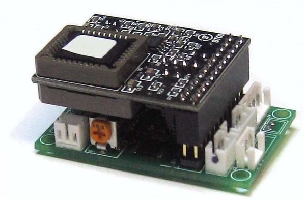
Here's a finished example of the buffered cable, it has my serial data buffer added to address any serial data attenuation issues.  This would primarily be an issue if you don't have a wireless IR link to the tender in a steam installation, and also any diesel installation.  Note with the buffered cable, you leave the existing Railsounds Generic Power Supply in place to provide the +5V required for the serial port buffer.

Wiring is also provided in the conversion cables to use the existing volume control, this is accomplished by removing the volume control on the Railsounds-Lite board and soldering those three leads in it's place.  You can then utilize the existing volume control instead of the on-board pot on the Railsounds-Lite board.

Below is the replacement cable graphic as well as schematics of the buffered and unbuffered cable.

Railsounds 4-5 to Railsounds-Lite Cable [buffered) graphic

Railsounds 4-5 to Railsounds-Lite Cable [buffered)

Railsounds 4-5 to Railsounds-Lite Cable

Note that the RS4 connector is depicted here, however the connections used are common to Railsounds 4 and Railsounds 5 boards.

Attachments

Images (3)
  • Railsounds 4-5 to Railsounds-Lite Cable (buffered) graphic
  • Railsounds 4-5 to Railsounds-Lite Cable (buffered)
  • Railsounds 4-5 to Railsounds-Lite Cable
Original Post

Replies sorted oldest to newest

@DennyM posted:

Will you explain what buffering is and does?

Very simple. You have a serial data source. It's digital, but a voltage. So say a high bit is 5V, and a low bit is below 1V. As you load the signal with more devices (sound card, smoke regulator, or other devices) suddenly that 5V is no longer 5V but more like 3V. Now the devices have problem differentiating what is a true high and true low bits.

A buffer is a device that amplifies this signal back to the original specification nearer 5V high and less than 1V low. (Actual values might be different, I'm just trying to give an example).

Last edited by Vernon Barry

Also, I should add the difference between just amplifying and true buffering.

This is because the problem may not just be what you consider the high bit. In other words, you think OK, so High is 5V and we have load, and because of that, the output sags to 3V and then we have the problem. No, the problem can be on the other end of the range, were the low bit is expecting that low below 1V shorted to ground nearer true DC zero. Some circuits are using the low bit with a pullup- and if that pullup is too strong (too much current) you also clip off the low bits (actual voltage never reaches below say that 1V threshold).

So true buffering is a signal output device with transistors for BOTH states, high and low, and less internal resistance for more signal "drive"- aka current.

The single transistor "emitter follower" is an example of amplifying- but only the high state 5V portion.

A true buffer is the new board @gunrunnerjohn came up with that uses dual state IC (chip) that actively "amplifies" both the high and low states.

Last edited by Vernon Barry

I've had mixed success with the transistor buffer over the years. In the case of using the ERR sounds, sometimes the serial being yanked too low could be resolved with a bit of trial and error swapping of R2LCs. It's not the most satisfying way to fix something though. I have a bunch of 741s kicking around to make a true op amp buffer if I ever run into this again. I almost never have this issue with the RS4/5 combo, it's just the ERR sounds. It kind of put me onto a long term 'side quest' to look at the serial comm more often in my projects.

John

I'm still trying to wrap my head around all the variations in TMCC electronics, so forgive these basic questions:

1.  Does the 24 pin connector plug into the motherboard where the old Railsounds 4/5 board was connected?

2.  If the failure is in the Railsounds 4/5 audio board, can you simply replace it with the audio board included in the Railsounds Commander kit?  Any downside in doing that (other than cost)?

3. If the failure is in the Railsounds Power board, can you retain the original sounds by plugging the old Railsounds 4/5 board into the Railsounds Commander board?

4.  If the failure is in the Railsounds Power board, it is not needed unless you need to power the buffer, correct?  Is there an option of using one of your little 5v power boards that you sometimes use in projects, or would there be a grounding issue?

Thanks for your efforts in improving and prolonging the life of our modern electronics!

Bob

@Norton posted:

Good work John, but you might want to put painless in quotes. Doesn’t appear to be quick, easy, or inexpensive considering the old alternative.

What's the "old" alternative?

I've had mixed success with the transistor buffer over the years. In the case of using the ERR sounds, sometimes the serial being yanked too low could be resolved with a bit of trial and error swapping of R2LCs. It's not the most satisfying way to fix something though.

That's exactly the reason I created the latest version of the serial data buffer.  It resolves any amplitude or drive issues of the transistor buffers.  Correct, it's usually the ERR RS Commander as it apparently draws more current through the opto-isolator for the serial data.  The R2LC/R4LC has very limited current capability on the serial data output.

@RRDOC posted:

1.  Does the 24 pin connector plug into the motherboard where the old Railsounds 4/5 board was connected?

2.  If the failure is in the Railsounds 4/5 audio board, can you simply replace it with the audio board included in the Railsounds Commander kit?  Any downside in doing that (other than cost)?

3. If the failure is in the Railsounds Power board, can you retain the original sounds by plugging the old Railsounds 4/5 board into the Railsounds Commander board?

4.  If the failure is in the Railsounds Power board, it is not needed unless you need to power the buffer, correct?  Is there an option of using one of your little 5v power boards that you sometimes use in projects, or would there be a grounding issue?

1. Yes.

2. No, the ERR RS Commander uses the RS-Lite board, a totally different form factor and connection.

Left Railsounds 4 audio board, right ERR RS Commander Board.


3. No, see above.

4. Yes, you can derive the power from anywhere, you just need 5VDC at around 20 milliamps for the serial data buffer.

Attachments

Images (2)
  • mceclip0
  • mceclip1

Very simple. You have a serial data source. It's digital, but a voltage. So say a high bit is 5V, and a low bit is below 1V. As you load the signal with more devices (sound card, smoke regulator, or other devices) suddenly that 5V is no longer 5V but more like 3V. Now the devices have problem differentiating what is a true high and true low bits.

A buffer is a device that amplifies this signal back to the original specification nearer 5V high and less than 1V low. (Actual values might be different, I'm just trying to give an example).

Thanks, I understand a little bit.

I lucked out a few years ago and found 8 of the ERR RS4 kits. I have used 3 so far and will be using most of the rest in projects planned for once my house and workbench get completed. These are not as simple to use as the new RS commanders but for $25 apiece, I will suffer with the extra effort to use them.

There is no IR capability on the ERR RailSounds Commander RS-Lite board.  You also don't get coupler and reverse light capability with the ERR RS Commander.

I see the board has a missing J8 header where the drawbar IR receiver usually plugs in. The solder pads are still there, any chance they’re still functional?

Also, I thought the LTC1 provided the rear uncoupler feature.

Last edited by rplst8

"Say that in plain English?"

Sorry about that.

Given the commercial availability of your cable (and instructions) and the currently available sound and command boards, how much more difficult would this repair be than it was previously?  Assume the ability to follow instructions and perhaps solder on the part of the amateur doing the repair.  Or an expert like yourself.

Last edited by Landsteiner
@rplst8 posted:

I see the board has a missing J8 header where the drawbar IR receiver usually plugs in. The solder pads are still there, any chance they’re still functional?

Also, I thought the LTC1 provided the rear uncoupler feature.

The missing header is non-functional, I tried it.

The LTC1 only works with Legacy 9-bit serial data, it won't recognize the 8-bit TMCC serial data.

@Landsteiner posted:

"Say that in plain English?"

Sorry about that.

Given the commercial availability of your cable (and instructions) and the currently available sound and command boards, how much more difficult would this repair be than it was previously?  Assume the ability to follow instructions and perhaps solder on the part of the amateur doing the repair.  Or an expert like yourself.

Well, that all depends on what the "previously" looked like.  One of the goals of my cable approach was to avoid making any mods to the TMCC motherboard since they're no longer available.  As long as you don't mind having the volume control on the ERR board, there is no soldering with my cable, it's plug-n-play.  I just added the volume control leads as an option because I know some folks do miss the volume control being accessible when doing the ERR installs.

Instructions?

  • Find a place to mount the ERR RS Commander board.
  • Plug 24-pin connector into Railsounds audio board position.
  • Plug the three connectors into the ERR RS Commander.
  • Put shell back on your engine or tender.

Wouldn't you also want to decommission the old RS power supply or are you using that to power the buffer?

If you need the buffer, I was using the RS Power board for power.  OTOH, you can add your own small 5VDC power supply and remove the RS Power board as well.  I was going for simplicity with the cable layout, the power is already there.

Add Reply

Post

OGR Publishing, Inc., 1310 Eastside Centre Ct, Suite 6, Mountain Home, AR 72653
800-980-OGRR (6477)
www.ogaugerr.com

×
×
×
×
Link copied to your clipboard.
×
×