All:

When my locomotive encounters this switch, there is a spark and the PH180 breaker trips.  The fuse in the circuit is not blown.  Travel is from top to bottom in the photo.  You can see some pitting in the right outside rail near the points.

IMG_8079

I have captured the event on video.  Please take a look.  I would like to know:

  1. What is actually occurring?
  2. How do I fix it?

Any help would be most appreciated.

George

Attachments

Images (1)
  • IMG_8079
Videos (1)
IMG_8078
Original Post

Replies sorted oldest to newest

@Farmall-Joe posted:

Is it just the engine in the video causing the short? It looks like the pickup roller is bridging the center rail to outside rail at that point (pitted rail just before the frog) so if its just this engine are the pick up rollers a little on the wide side compared to other engines you might have?

I agree.  I have this issue with a few passenger cars on FT switches.  I just put a small piece of electrical tape or other insulating material on the end of the center rail closest to the outside rail.

switch

Attachments

Images (1)
  • switch
@MartyE posted:

I agree.  I have this issue with a few passenger cars on FT switches.  I just put a small piece of electrical tape or other insulating material on the end of the center rail closest to the outside rail.

switch

Marty!  Wow.   I put a small piece of insulating black electrical tape on the outside rail (covered up the pitting) and it worked!!!!  You really rescued me! 

And Joe, thanks for looking at this issue as well.

I'm thinking that applying some Liquid Tape to the insulating rail might provide a more permanent solution, but this will definitely get me past the open house.

Once again, Thank You!

We're going to test this section of track with a few more locomotives and see what happens.

George

@Farmall-Joe posted:

K - still going with what i and Marty indicated.  I'd try the elec tape first where the center rails are really close to the outside rails and see if that helps.  If so a more permanent solution is to file off the some of the center rail where it gets close to the outside rail.

My apologies, I might not be understanding you correctly.   Here's a closer look at the switch (tape installed). Maybe someone can highlight the area I should be checking.
IMG_8084

George

Attachments

Images (1)
  • IMG_8084
@G3750 posted:

My apologies, I might not be understanding you correctly.   Here's a closer look at the switch (tape installed). Maybe someone can highlight the area I should be checking.

George

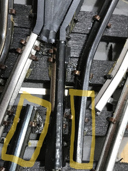
You could go with what you depicted or Marty or i was thinking the center rail towards the end where it bends towards the outside rail.  See the yellow highlighted areas.  You video shows it shorting on the straight part but i marked up both the straight and diverging areas. Your insulation as placed should take care of both routes however so try it as you have it now.

IMG_8084

Attachments

Images (1)
  • IMG_8084

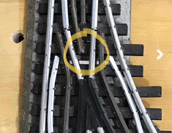
OK, so that first situation seems to have calmed down.  But I had a similar event occur at the north side of the layout.  Switch #33 is a RCS LH031 turnout.  In the straight position, this switch has been performing very well.  For the first time, I set it to diverging and tried to run a locomotive through it.  The PH180's breaker popped.  When I reset the breaker, the fuse blew.  Here's the switch in question (of course it's hard to reach).  The outside rails look OK, but the center ones are pretty crufty.

IMG_8090

Any thoughts on this one?

Thanks,

George

Attachments

Images (1)
  • IMG_8090

The move-able points, and the two short track pieces, leading to the move-able points, need to be isolated/(insulated). Sometimes, the small track nails, provide enough continuity, to allow for an un-wanted current path. You would also need to check, roller contacts, on different engines. As power trucks flop-around, intermittent continuity/shorts can cause problems.  Side note:  Best to have all track sections, on the same transformer electrical phase, (another can of worms). Have fun, Mike CT.

Last edited by Mike CT

The center rail looks fairly close to the outside rail right were it ends. Looks like it should be over a bit more to the right looking at the pic. so that it’s centered. As Mike stated. Those short isolated rails have the wheels run on them on the diverging route and the rollers pass over them on the straight route. They should be isolated and dead as far as current.

  If the back side of a wheel comes in contact with the center rail. It won’t short to those isolated rails. But it will travel through the axle and go through to the solid outside rail on the curve.

04D1D5E5-2F04-47A6-9D1E-A6676BAAA1C9

Sometimes engines designed for tight radius tend to cheat a bit as far as gauging. The flanges are in a bit and compensated with a wider rim. Gives them a little more freedom on a tight curve. I have an old Ross 3 way. For the most part it works well. A few engines have had issues. I found the engines that worked the best that I owned were the Premier 0-8-0’s from MTH with the 3 to 2 rail capability. It’s in a yard area and that’s what I assign there.

Attachments

Images (1)
  • 04D1D5E5-2F04-47A6-9D1E-A6676BAAA1C9

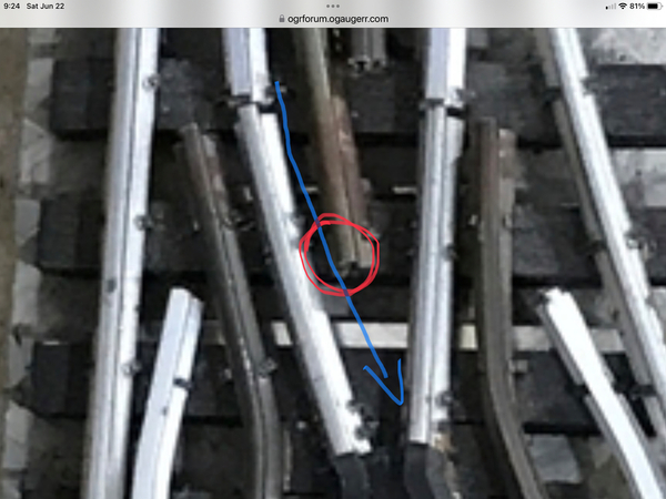
I’m with Dave on this one, …..most of the time I get asked about this particular problem, it’s a diesel, and it’s fat wheels designed around tighter curves for marketing. I’ve circled what I would look at first. The blue arrow represents the the fat wheel coming through and getting oober close to the power ……you can confirm this by looking for witness marks on the wheels and the track. I’ve trimmed that power rail on stubborn offenders to get the backside of a wheel to pass by it without rubbing…..

Mike also brings up a good point about pickup rollers bridging a section,….I’ve seen that more than once, especially if the roller is super wide, like older Williams pieces have.

The best procedure I’ve used to diagnose this issue is to set the engine right where it croaks, cold with no power and tilt the engine from side to side observing what’s touching and what’s not touching…….a continuity tester on your DVM can be a friend here too,

PatIMG_9197
Attachments

Images (1)
  • IMG_9197

Add Reply

Post

OGR Publishing, Inc., 1310 Eastside Centre Ct, Suite 6, Mountain Home, AR 72653
800-980-OGRR (6477)
www.ogaugerr.com

×
×
×
×
Link copied to your clipboard.
×
×