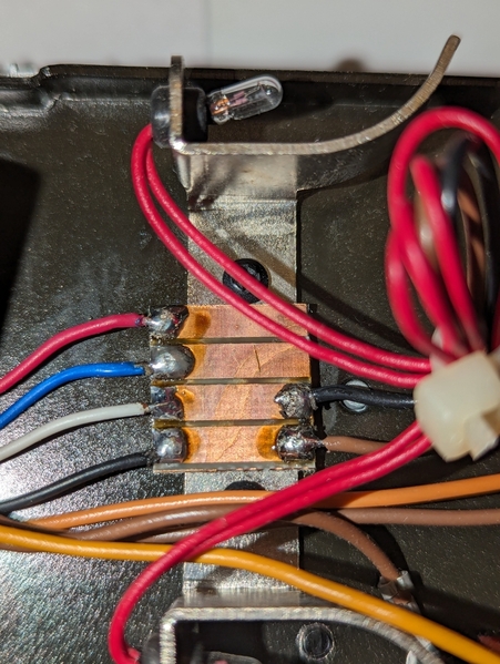
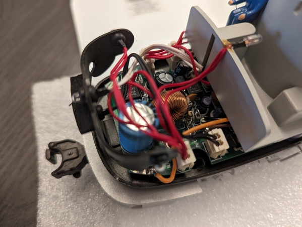
Hi,   I’m replacing a QSI DCRU board with a MTH PS1 Master/Slave system for my Alco powered A and powered B engines.  John (gunerjohn) helped me with this system and am now familiar with how the main drive system functions and how to wire it.  Now, I’m trying to learn the lighting system.  I have two similar small pc boards mounted in the front cab sections for both the powered A and dummy A units.  Photo attached.  These boards have an orange-colored conductor supplying 15Vac, and a Black and a Brown conductor.  The black and brown conductors in the powered A unit connect to the DCRU board and I’m pretty sure they connect via circuit trace to one of the NEC relays.  I know the small pc boards supply the front markers, the side markers, cab interior light, and what I call the Mars headlight and the headlight below the Mars Light.  I’m not sure what the correct terminology is for these lights – sorry.  I’ve also attached a photo of the tether connection wiring in the dummy A unit showing the four conductors terminated via solder bar showing where the black and brown conductors feed the small pc board.

My question is for someone familiar with the forward/reverse lighting operation of the QSI-DCRU unit;  could you explain how this works? PXL_20240220_180558083Inside chassis_7   Thanks very much for your help.   Bob
Attachments

Images (2)
  • PXL_20240220_180558083
  • Inside chassis_7
Original Post

Replies sorted oldest to newest

It is not Head Light from the PS-1 board.  CV boards that MTH used in the ABA, AA slave sets up pickup a voltage off the Relay operation.  When the relay is active to drive the engine in a certain direction it triggers the directional lighting.  When Fwd relay active on the Lead PS-1 unit the lead HL goes on.  When the engine is reversed the Lead HL goes out.  The Slave board reverse relay is active and it triggers the reverse CV board HL and it goes on.

I never fully documented the circuit, but know where the leads are connected and that is the source to trigger CV board.  Hence the 6V bulb.

PS-1 boards have output for direction HL but at 1.5V.  Diesels use that and steam tenders for the Tail light.  G

Are you sure and did it work?  That output is about 1.2v, is that enough for those early isolators?  I have upgraded many of these units from 1994 through the end of PS-1 in 1999/2000.  The source was across the coil of the relays.  Much higher voltage drop.

I won't say never, but I have not seen it. Plus the DCRUs used in the trail A did not have the light mod added.  They were basic reverse unit, so there was no HL output to drive the CV board in the trail A.  G

Add Reply

Post

OGR Publishing, Inc., 1310 Eastside Centre Ct, Suite 6, Mountain Home, AR 72653
800-980-OGRR (6477)
www.ogaugerr.com

×
×
×
×
Link copied to your clipboard.
×
×