resistors and diodes
Original Post


|
|
resistors and diodes
Replies sorted oldest to newest
Brian: What type of track power are we talking about? Is it steady 18 VAC as used with DCS or is it variable AC as in conventional operation. It might even be DC as with the simple LionChief sets.
LEDs like to be run on DC rather than AC. You can use a full wave bridge rectifier to convert from AC to DC or just a diode to obtain half wave rectification. You can add a capacitor to smooth out the ripple in the rectified DC if that's a concern; for an LED alone, it generally is not important.
Tell us more about what you're trying to do.
Well it would be dcs WiFi mth feeding through legacy system.
Brian
Also what I'm doing is rebuilding lionel 6-12062.replaceing the old bulbs with led's that are 3v and need the correct resistors to operate with track power.
When it come to resistors and things like that I'm not very good at it.
So any help would be very helpful and do appreciate anything you could do to help me.
Thank you
Brian
So this is a crossing gate. The accessory may be powered from the track but it is not clear that the lights (the flashers) are at the same voltage. Can you measure what voltage is going to the bulbs that you want to replace?
I'll get back with on that.
Brian
220 to 330 ohm resister should be fine with a diode
Take a look at this recent OGR thread about replacing bulbs in the 6-12062.
Apparently there are 2 versions of the 6-12062. One uses bulbs, the other uses LEDs.
If you already have the LED version, then just replace the LED (minding polarity). If you have the bulb version (apparently 14V incandescent bulbs), I believe you might find the bulbs are driven with DC voltage. That is, circuits that alternate flashing bulbs are typically done using DC. This means you would not need the diode...just the resistor to lower ~14V DC to ~3V DC. Of course you'd still need to mind the polarity.
If you have a multi-meter, measure the DC voltage going to a working lamp (whether it be an LED or a bulb). You will know it's DC voltage by swapping the meter leads and observing the sign (+ or -) on the meter will reverse but the voltage reading will stay the same. If the voltage is above 10V or so, then you have incandescents inside. If the voltage is below 5V or so, then you already have LEDs.
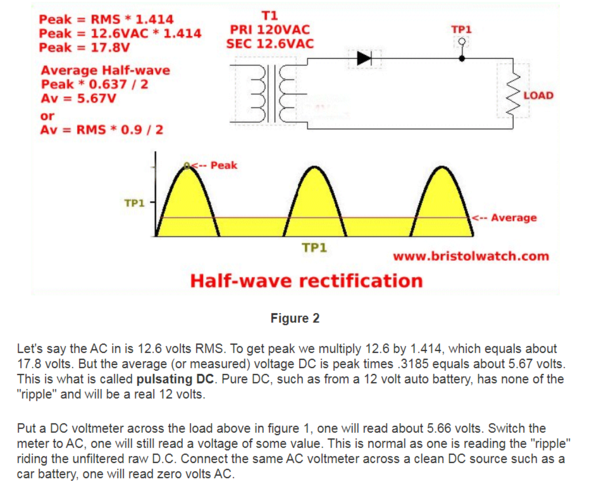
Here's a question about half-wave rectification. In a configuration like the one shown below, what kind of voltage would you get out of the initial diode? Would it be considered AC or DC voltage in terms of reading the output with a meter? What would be the voltage? Does it have anything to do with the 1.414 ratio value that comes from AC through a bridge rectifier?

Thanks for any help!

Use the LED wizard - very helpful. http://led.linear1.org/led.wiz
Bruce
If you are running on track power, you should use a diode and a resistor. For up to 18V track power, a standard 1N4003 diode and a 470 ohm 1/4W resistor will handle one standard LED.
bruce benzie posted:Use the LED wizard - very helpful. http://led.linear1.org/led.wiz
Bruce
Not that helpful when you don't have the values to feed it.
I have a number of LED s as headlights in locomotive and I use no resistor less than 1000 ohm. I generally try one out and if the LED is too bright or too dim, I change to a different resistor rating. Typcially I have used 1500 ohm and adjusted to 1000 or 2000 as needed.
I am using mine with outputs from DCC decoders which are 12 V DC or in that range.
I like bright headlights. I do pick the LED color temperature to match the locomotive type and vintage. I go from bright white to amber as they get older. ![]() 1,000 ohms with an LED across 12VDC gives you 9ma, so that will be decently bright. I tend to go big and use a 470 ohm, I get close to 20ma.
1,000 ohms with an LED across 12VDC gives you 9ma, so that will be decently bright. I tend to go big and use a 470 ohm, I get close to 20ma.
For class lights and tender markers, I frequently go much larger with the resistor as I don't think they should compete with the headlight. ![]()
gunrunnerjohn posted:If you are running on track power, you should use a diode and a resistor. For up to 18V track power, a standard 1N4003 diode and a 470 ohm 1/4W resistor will handle one standard LED.
The question I have is what the voltage is after the diode.
Let's try your numbers using a 3 volt 20ma LED:
R = (Vs - Vf) / I
470 = (Vs - 3) / .020
(Vs - 3) / .020 = 470
(Vs - 3) = 470 * .02 = 9.4
Vs = 9.4 + 3 = 12.4 volts
Then we check it with the LED resistor calculator:

Indeed it checks out to 470 ohms using 12.4 volts as the supply voltage.
But how do you determine this given an AC voltage through a diode? How is 18 VAC track power changed to 12.4 volts half-wave DC?


Having divided 18 VAC by the targeted 12.4 volts half-wave DC, I come up with a ratio of 1.45; a value that I've run across in my reading about diode rectification. If that's all there is to it, we get:
Vdc = Vac / 1.45
or using the reciprocal of 1.45 gives 0.69 so
Vdc = Vac * 0.69
Can anyone confirm this for me?
This would seem to indicate that my last post is incorrect. They even go so far as to explain what a volt meter reading will give for this circuit. Their calculation is:
Vdc = Vac * 0.45
That doesn't work with the above 18 VAC to DC conversion. According to this, Vdc from 18 VAC (rms) would be 8.1 VDC (average). I'm not sure what to think.

Consolidated Leo posted:gunrunnerjohn posted:If you are running on track power, you should use a diode and a resistor. For up to 18V track power, a standard 1N4003 diode and a 470 ohm 1/4W resistor will handle one standard LED.
The question I have is what the voltage is after the diode.
Let's try your numbers using a 3 volt 20ma LED:
R = (Vs - Vf) / I
470 = (Vs - 3) / .020
(Vs - 3) / .020 = 470
(Vs - 3) = 470 * .02 = 9.4
Vs = 9.4 + 3 = 12.4 volts
Well, nowhere does GRJ say his circuit is driving 20 mA into the LED. I figure he chose a resistor value which gives a suitable brightness.
Your relationships in your most recent post look correct. The average voltage (as measured by a voltmeter in DC-mode) will be around 8V DC for an 18V AC (RMS) input. This is a practical value to use for hobby purposes. As the diagrams show, the voltage is pulsing reaching a peak of ~25V = 1.4 x 18V. But it's also 0 half of the time.
At the peak 25V following the diode, the 470 Ohm resistor limits the 3V LED current to about 45 mA = (25V - 3V) / 470 Ohms. But the current is also 0 half the time.
The actual math is quite complex involving non-linear equations which themselves are just models of the underlying semiconductor physics. There is also the issue of the voltage drop across the diode where you lose between 1/2 to 1 Volt depending on more non-linear equations.
Again, I emphasize the "practical" use of the relationships in your diagram. So 8V (average) thru a 470 Ohm resistor into a 3V LED suggests "only" 10 mA (average) of LED current. I suggest this is a good enough approximation for hobby work.
hello.
i have 6 standard 3v leds
The 470 ohm resistor was picked empirically, I made no attempt to do a "pure" calculation to get exactly 20ma average current.
Also, I sometimes add a capacitor into the mix to eliminate flicker of the LED. The cap typically charges to the peak voltage, so the current limiting resistor is sized to handle the peak voltage from the half-wave rectified track power. With 18V track power, the peak voltage of the half-wave power is around 12.6 volts, so my resistor is selected to handle that voltage. Truthfully, I simply ignore the diode drops as they're not that significant for this application.
The beauty of using LED's is it's not rocket science. As long as you don't let the average current go over the LED's rating, you can do pretty much anything you like as far as current limiting. I use all sorts of different current limiting values, depending on what lighting effect I'm trying to accomplish.
If you want absolute maximum brightness from your LED's without risking running them over spec, simply use DC and compute the resistor exactly.
thank you i order 470 ohm resistors and a 1n4003 diode.
gunrunnerjohn posted:...
Also, I sometimes add a capacitor into the mix to eliminate flicker of the LED. The cap typically charges to the peak voltage, so the current limiting resistor is sized to handle the peak voltage from the half-wave rectified track power. With 18V track power, the peak voltage of the half-wave power is around 12.6 volts, so my resistor is selected to handle that voltage.
The peak voltage is 1.4 x 18V = 25V whether there's a capacitor or no capacitor. The capacitor provides reserve energy and supplies voltage during the half cycle when there would otherwise be 0 voltage. The practical effect is the average voltage increases from ~8V toward 25V as you increase the capacitor value. Knowing the peak voltage is important since capacitor selection is based on the peak voltage applied. For 18V AC track voltage, I'd use a 35V (or higher) capacitor.
As GRJ says, the capacitor smooth the pulsating voltage so that you demote visual flicker/flashing of the LED. Teenagers can see this flicker but the typical OGR reader lost the visual ability to see this years ago...![]()
Thanks guys! That is helpful.
BKM: I hope you don't delete this. These discussions are useful for future reference. I know we kind of got off the track trying to answer your questions. But these issues are not off topic for what you are trying to accomplish.
I agree with Leo. Consider leaving it for so others can benefit in the future. I believe you're the only one who can change the title of this thread so maybe change it to something like "Selecting resistor for LED driven by AC track voltage" or something like that.
Leo, if this thread does get deleted consider starting a thread with your musings! This seems like a very relevant topic yet I can't recall a concise OGR thread which specifically goes under-the-hood of what is really going on with a diode-resistor-LED combination driven by AC track voltage! From what I can tell, all those LED calculators/wizards assume pure DC voltage.
i thought i was suppost to delete them but i don't how anyway.can you tell me how to delete .
i don't have any idea how any of it works.but i'll leave up.
Stan: Will do. I actually considered starting a new thread when I brought up my questions; but it seemed to fit in with this topic at the time. Math seems to turn people off. That's a shame. Simple algebra is not that difficult. But when it involves calculus and all those squiggly lines, I loose interest as well.
Thanks Brian! No, it is not customary to delete topics from the forum. However, there are times when someone starts a new topic but then decides that it was started in error. When that happens it is possible to delete it.
I am unsure how that works but I know that the member who starts a topic has the ability to delete it as well. No one else can do that. Only the moderators and you.
Okay. I did a quick test. When you click on the topic that you started, and you are at the beginning of it, there should be a box to the right that includes "Manage Topic" as an item to click. Then when you click it, a drop down list appears that includes a "Delete Topic" item. Click that and the topic and all of it's replies disappear. That's how it's done.
Thanks again for leaving this up!
I don't believe the OP can delete a topic once it has any replies.
Here's a thread I created, it has replies. Note that when I try to delete it, that option doesn't exist now.

However, if I pick one of my topics in For-Sale that doesn't have any replies, I am presented with the option to delete.

You can delete one of your own posts in a topic if you're not the thread starter.


GRJ: How about that! This software is smarter than I thought. Good to know!
Access to this requires an OGR Forum Supporting Membership
