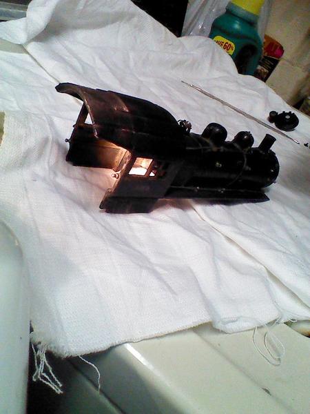
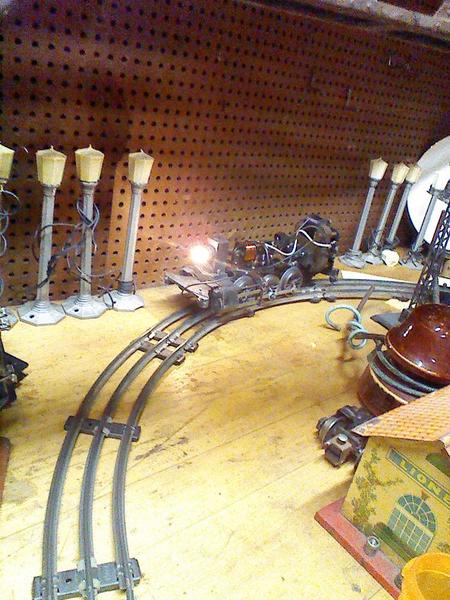
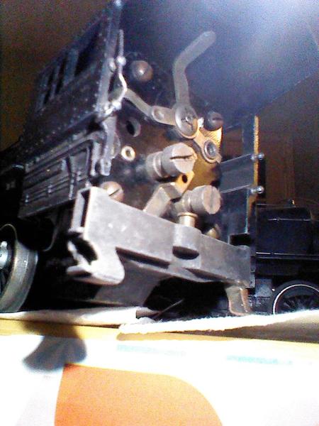
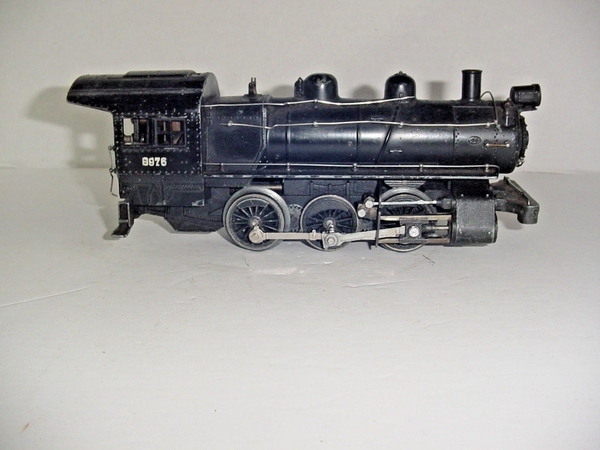
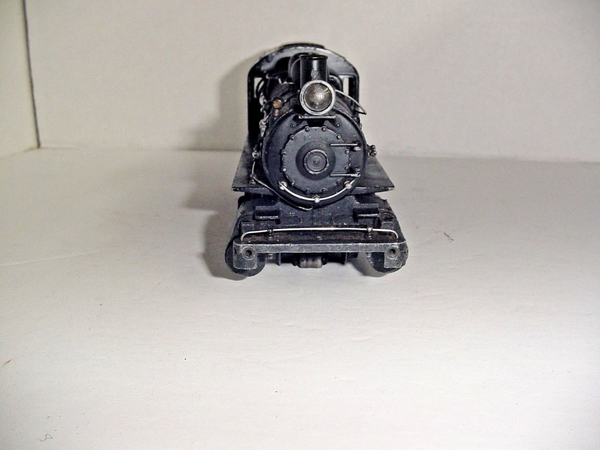
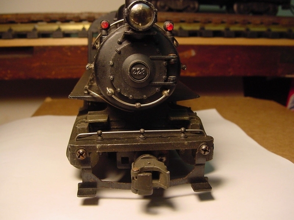
I picked up this rather beaten up steam switcher recently which has lots of issues. The rods are all there, some handrails, no smokebox nor headlight. Also, no tender as of now, but the seller may still have that. The wires were in bad shape and so far it does not run. Without the tender and without the smokebox, not sure if it is a 227, 228, 230, 231, 232 or 233. For now, I am assuming it is a #227. My last "basket case" steam switcher was another beaten up #231. My friend helped me with the wiring on that and it runs a smooth as silk now.

Some of the parts I need are on  their way already. I was able to swap out the front smokebox area with a new section from Jeff Kane, The Train Tender. I think that is quite a step forward.

Much of the work has been thoroughly cleaning the locomotive from the drivers to the gears. My friend (yes, the same victim/volunteer who helped on the #231) and I spend around 3 hours the other day. There was such an accumulation of gunk and hardened grease that we had trouble turning the wheels/gears. Mineral spirits worked pretty well in cleaning out the drivers. It was only after all the cleaning that we realized the brushes were missing!

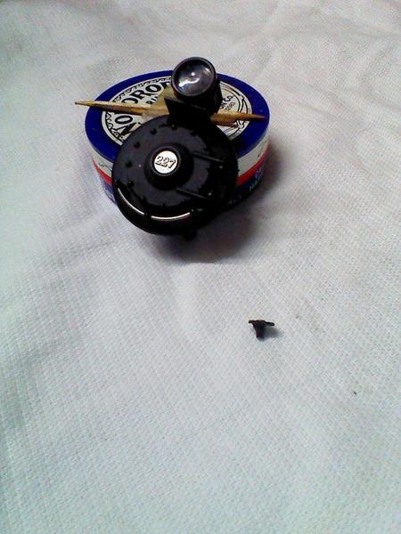
The only parts which I can't seem to find from the different online parts folks (including Jeff) are the brush holding retaining nuts that screw on to hold the brushes in place at the back of the cab (I was actually able to find the brushes/springs and they are coming in the mail).  Once I have the brushes and the retaining nuts, I will attempt rewiring the locomotive.

Anybody have 2 of these brush retaining nuts in their parts bin?

Tom

Mostly 8976 repairs June 2016 014Mostly 8976 repairs June 2016 015Mostly 8976 repairs June 2016 018Mostly 8976 repairs June 2016 021Mostly 8976 repairs June 2016 022Mostly 8976 repairs June 2016 024Mostly 8976 repairs June 2016 025Mostly 8976 repairs June 2016 030Mostly 8976 repairs June 2016 034Mostly 8976 repairs June 2016 040Mostly 8976 repairs June 2016 043Mostly 8976 repairs June 2016 045Mostly 8976 repairs June 2016 046Mostly 8976 repairs June 2016 017

Attachments

Images (14)
  • Mostly 8976 repairs June 2016 015
  • Mostly 8976 repairs June 2016 014
  • Mostly 8976 repairs June 2016 017
  • Mostly 8976 repairs June 2016 018
  • Mostly 8976 repairs June 2016 021
  • Mostly 8976 repairs June 2016 022
  • Mostly 8976 repairs June 2016 024
  • Mostly 8976 repairs June 2016 025
  • Mostly 8976 repairs June 2016 030
  • Mostly 8976 repairs June 2016 034
  • Mostly 8976 repairs June 2016 040
  • Mostly 8976 repairs June 2016 043
  • Mostly 8976 repairs June 2016 045
  • Mostly 8976 repairs June 2016 046
Last edited by PRR8976
Original Post

Replies sorted oldest to newest

Wow, I had never seen the insides of one of these before; thanks for all the photos! I was very surprised to see that strange little e-unit--I have the 1989 reissue, and that just has the standard e-unit, mounted horizontally, with a return spring. If you can't get the original working, perhaps one of those will fit.

There are a lot of interchangeable parts between the 227 family of prewar switchers and the 1989 reissue (18000), but the motor and e-unit are not amoung them.  The 227 e-unit (OO1E-185) is from the prewar OO line of locos. The 227 family of switchers is the only place it is used in O gauge that I know of. In my opinion it is superior to the standard three position O gauge e-unit.  It is certainly much easier to work on.  The problem with it is there are no parts available. The OO e-unit complete is available from several sources, but it is not cheep.

There was an article written "Lionel's #8976  - Wiring and Operation" by William J. Krone which describes how to rewire all these locos and including wiring diagrams.  I have a copy of it, but my copy does not indicate what publication it is from or the date. It might be the TCA  Quartery.  Maybe the TCA library could help.

 The missing brush tube caps may be either the 700E-305 or the 400E-115. There are two different types and I can not tell which is which. One screws on the outside of the tube and the other into the inside. They were used on the 400E, 700E, 763E and 227 family of switchers. They should not be too hard of find. I had one loco which had washers sholdered on the ends of the brush tubes to keep the brushes in. 

Thanks everyone. 

Chuck--I've bought things from Dennis before but somehow forgot him as a source, thanks for the reminder.

David-- Thanks for mentioning the Krone article. I have that in my library of books/articles. With all the damage this loco absorbed (substantial enough to knock off the headlight and put a good dent and what can best be described as a tear/rip in the cab roof), the wiring is just one thing to worry about. These are pretty tough little buggers so I'm fairly optimistic. 

Tom 

Last edited by PRR8976
David Johnston posted:

... The missing brush tube caps may be either the 700E-305 or the 400E-115. There are two different types and I can not tell which is which. One screws on the outside of the tube and the other into the inside. They were used on the 400E, 700E, 763E and 227 family of switchers...

David,

 I remember seeing a parts list for the 227-series locomotives and the part was listed as 700E-305 Brush Holder Screw. There is also a "Brush holding Retaining nut" (part# 400E-118, which is maybe internal) on the same parts list which I had originally identified in my original post which I thought I needed, but if it screws on (which it does) I guess it is the "Brush Holder Screw." Thanks for helping me to clarify that so I know what to ask for! 

 El Classico mentioned German clocks earlier which is actually what I thought of as my friend and I started taking this loco apart the other day...to see the craftsmanship of the 1930's, with so many little, well-made, intricate parts.

Tom 

As best as I have been able to figure out, Lionel changed from the 400E style brush tube to the 700E style brush tube when they started using brushes with shunts on them.  Maybe some time in 1938.  The brush tube with the cap gave them a way to clamp the washer at the top of the brush spring that the shunt is attached to.  This gives a good electrical path from the shunt into the brush tube.   I have not seen the 700E-35 part number before. I wounded if it is a typo of the 700E-305 part number.  There are lots of errors in the part lists.

The 227 family of locomotives are great locos.  It is too bad they did not make it into the post war era.  I recently ran into a set of wheels which I am sure came off a 227 type loco.  They did not look right and after studying them I discovered they had been insulated for two rail operation. The flanges and tread were scale size, even smaller that the tires that came on the 701. They had the cam on the back that operated the valve gear.   I wonder what happened to the loco they came off of. 

David Johnston posted:
  I wonder what happened to the loco they came off of. 

Yes, too bad our locomotives don't come with the histories of who owned them and for how long. You rarely know whether you are owner #2 or #32. 

I've said this before on other threads, that most of my locomotives are around 77 years old. Properly maintained, they can easily go another 77 years or more. Knowing that they were so well made and manufactured here in the US is a big part of the appeal, at least to me. 

Tom 

jim pastorius posted:

Now you have piqued my interest in these locos except they are too expensive for my budget unless I find a beater to fix up. Interesting thread. Always more to learn. Thanks

In my original post, I forgot to mention one of the drivers has a slightly bent flange and a few rods are dented, too. I think they are more cosmetic issues than anything that will impact its ability to run well.

When the drivers and frames were scrubbed pretty well it actually started looking pretty good (picture #8 from the top)...but oh those wires! Well, I said I am an optimist! 

Tom

Hi Rich,

  Thanks. I think I will be OK on the tender. The guy who sold me the locomotive said he was pretty sure he had a tender, but had to dig it out.  If you have any train stores with prewar parts, if you don't mind asking, I'm still having trouble with the brush holding "cap" that screws on and holds the brushes in (need 2 of them for a #227 loco). 

Thanks, 

 Tom 

Last edited by PRR8976

UPDATE: I got all the parts that I need so far, a big thanks to Harry Henning again for the elusive brush caps. So, after a couple of hours soldering wires and doing some more cleaning of the drivers/rollers, I was able to get the e-unit to get moving and heard some humming. Unfortunately, I never got the motor to actually budge. I will try again over the weekend.

Any suggestions? Keep in mind that this was pretty filthy and who knows when it last ran. Reminds me of the 1990's when I used to go to a train store in Tuckahoe (and later Scarsdale), NY, Trent's Trains, and the owner used to liberally spray WD-40 on any motor which wouldn't run and usually had good results. Would that help at all? 

Tom 

Last edited by PRR8976

Isn't this similar to the 1980s Lionel repro of the PRR B6?  I am not well versed in the part numbers, but it seems that 701, 708, and some of the 220- series all use the same major parts?

Mine is now 2-railed, and has 717 tender trucks, and is a lighter shade of Brunswick green.  It, too, had a bent cab, and I was unable to straighten it.  Some delicate fiberglas work fixed it - you cannot tell.

I can't post pictures, but here is its URL:

[URL=http://s667.photobucket.com/user/bobturner_trains/media/Steam%20Locomotives/700s001.jpg.html][IMG]http://i667.photobucket.com/al...omotives/700s001.jpg[/IMG][/URL]

Hi Tom. Good to hear of your progress with the 227. Great little loco. I do not know if you took the e unit apart yet or not. If not that would be my next step.  There is a little brass shoulder screw with a nut on the end of it.  Remove that screw and the E unit drum will come off the contact plate. Then you can clean up the contacts on the contact plate. Be really careful with the contacts on the drum. They are spring material and are silver plated. Clean them with something non abrasive so not to remove the silver. The black silver sulfide is conductive, so it does not need to be removed. The silver acts a lubricant helping to get the drum to move. The contacts are held onto the drum with tiny drive screws.  Lionel had the presence of mind to drill the drive screw holes all the way through the Bakelite, so with a very small punch you can drive the drive screws out and remove the contacts.  This would allow you to reshape them. Also I have seen where a new contact was soldered on. I have also seen new home made contacts. With the drum removed you can jumper ajacent contacts to get the motor to run and rule out motor problems. 

The wiring should go from the collector rollers to brush plate on the contact opposite the switch that turns the e unit on and off. There should also be a wire directly from the motor field to this point. The other end of the motor field should go to upper rear contact on the e unit.  The lower forward e unit contact should have a wire coming from the e unit coil and then ground to the loco frame. The two brush wires should go to the upper forward and and lower rear contacts on the e unit.   That is all the wire needed to make the motor run. 

As for WD-40, it drys sticky in time. I would never use it on a train.  The CRC contact cleaner has been recommended on this site. It is what I use.  Let us know how it comes out. 

Last edited by David Johnston
David Johnston posted:

Hi Tom. Good to hear of your progress with the 227. Great little loco...

The wiring should go from the collector rollers to brush plate on the contact opposite the switch that turns the e unit on and off. There should also be a wire directly from the motor field to this point. 

Hi David,

  Thanks very much. I will need to re-check the wiring. So, for the upper tab on the motor on the engineer's side, there should be 2 wires soldered on there? I think I only had one...for the collector rollers. Where does the second wire go to, from that same tab to where? 

Thanks again, Tom

Tom, from that upper tab on the engineers side of the brush plate there is the wire from the collector roller, a wire from the motor field, a buss bar going to the e unit shut off switch, and a socket for a wire going to the tender that powers the bell. The field wire is a single varnished strand coming from the end of the field just above the tab. 

I'm sort of at a standstill now, with no additional progress. I plan on looking at this next Friday at my friend's house, as we may need to rewire everything. I still hope that all goes well and I don't need more parts.

In the meantime, if I can ask a stupid question to JAGRICK, David Johnston or Harry Hennings... if I want to test the motor with running two wires from the center rail and ground rail directly to the motor, where exactly can I attach the wires? If you can use engineer's side and fireman's side to clarify which side, it would make my life easier. Thanks.

Tom


Tom, to get the motor to run you need to connect power to one brush, connect the other brush to one motor field lead, and connect the other motor field lead to the other power wire. Looking in the cab from the tender what you see is the brush plate.  Above the brush plate is the motor field coil.   The leads for the field come out on the engineers side. One goes to a terminal on the brush plate, the other goes forward to the e unit.   The brush holders are on the lower edge of the brush plate.  They each should have a lug that comes to each side of the brush plate. Normally those lugs would be connected to yellow wires that go forward to the e unit. 

When connecting the motor to power wires, it does not matter which wire goes to the brush or field. It is AC and the wires have no polarity.  They are interchangeable.  

Connect one power wire to either brush lug.  Use a jumper wire to connect the other brush lug to one of the field leads.  Connect the other field lead to the other power wire.   The motor should run, but it must have good brushes in it.  To reverse the direction reverse the power wire and jumper to the field on the brush lugs. 

I would suggest you take the motor out.   With all the wires disconnected it only requires removing the two mounting screws on the front. To rewire the loco the motor has to come out as the rear collector terminal is under the drive shaft. With the motor out you can remove the screws that hold the gear unit cover on. This will let you remove the cover , which has the e unit mounted to it. With the cover off , and the gasket if it stays with the frame, you can lift the worm shaft out. The bearings will come with it. Now you can get to the rear collector lug. 

This may sound like a lot of work to get to a lug to solder on a new wire, but this gives you access to the interior of the gear box, which is probably full of very old hard grease, which needs to be cleaned out and replaced. With the worm shaft out you can remove, clean and relubricate the bearings on one end of the shaft.  To get the bearings off the other end the gear needs to be removed by loosing the set screw and tapping it off. The things that look like washers are actually hardened and ground thrust washers. The side the ball bearings are running against need to continue to be the wear side. 

The weak point in this loco is the fiber gear on the end of the worn shaft. It's condition will determine the future of the loco.  I have never found any sold as spare parts, but they might be out there somewhere. I also remove the gear on the motor shaft so I can remove the armature from the motor to clean it and get oil in to the front bearing.  There is a second bearing on the motor shaft that sits on the commutator.  Keep track of that as it needs to go back on.  If the set screws in the gears are slotted so they can be removed with a straight blade screw driver, they may break when being removed. Replace them with set screws with a recessed hex drive.  That will make life so much easier.  

REVISED!

Before I get into the nitty gritty details, I need to give "Special Thanks" to 3 people for going above and beyond with this project:

1)Harry Henning and his folks are great to deal with and are so honest, it is refreshing. No wonder why his store has been around so long.

2)David Johnston must have worked in a prior life at the Lionel factory assembling prewar steam switchers. How he knows what he knows is beyond me. I could not thank him enough for his support.

3)My friend Bill who has the unenviable job of helping me out when things go wrong with my switchers.

(honorable mention to Myron Biggar for the set of screwdrivers he gave me at a Greenburg train show at Yonkers Raceway, back in the 1990's)

I recently got back my "basket case" of a locomotive from Harry Henning. Harry had the lower half of the locomotive assembly. Now keep in mind that this locomotive was severely abused by a prior owner and it needed lots of work. Some of what was needed included: rewinding the coil for the e-unit, I believe all of the wiring was replaced, the drivers were dinged and dented needing replacement, the idler gears were shot and needed replacement...and that may just be a fraction of what Harry and his folks worked on. Luckily, I had a donor locomotive that I bought years ago if ever needed for such a project. The donor steam switcher donated drivers and idler gears.

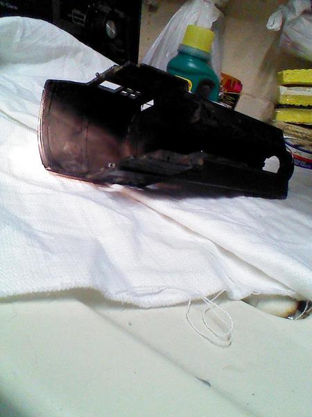
While that was happening, my friend Bill, who helps me with the less severe types of repairs did some great work on the cab roof. The cab roof was no longer "round" most like from a drop or several. It also had a rip/tear on one edge. Bill hammered out the rip and then we figured that we should try to reinforce the roof. Looking around his basement, I noticed a familiar shape and asked, how about this tuna can? So, Bill used tin snips to cut a small section out of the can and then we epoxied it to the underside of the cab roof. I wonder if the cats in my house will have an unnatural attraction to this particular locomotive now!

Tonight...Upon receiving the lower assembly back from Harry Henning, I still needed to do some minor work. Tonight was a pretty big step forward. I had to flip a plate under the e-unit, I wired the headlight to the new wire Harry left for me, I drilled out the repro 653 number plate for the new smokebox assembly and replaced the 653 number plate with a new old stock #227 number plate which is more representative of the vintage nature of this locomotive.

So, how does it run? I had emailed David Johnston earlier today and he gave me some more advice. The last sentence summed it all up. He said:

Should run like a Swiss watch.

By the way, she does! I could not have been happier.

More to come in the next few weeks:

  • Putting all the rods back on
  • Putting the front smokebox assembly on
  • Putting the boiler shell on
  • Putting on the front pilot/steps
  • Running it with the #2232B tender purchased to be its mate
  • Replacing the missing marker lights on the boiler


So, summing up... here we have a locomotive that is in its mid to late 70's as far as age, made in the USA when this type of craftsmanship was indeed like a Swiss watch and it now ready to start another 70 years of operating.

Thanks again for everyone's interest and support.

Tom

Edit from Spring 2024- It was around this post that we used a Krylon can of black (flat) if I remember correctly...taping off all but the cab roof. So, the top of the cab roof got a coating to cover the repair we made. In one of the photos below (2 down from here), you can see the lines of the tuna can we epoxied on the underside of the cab roof. Also, if it gets confusing to follow, I changed by OGR handle from "MNCW" to "PRR8976."
IMG_20161203_212928IMG_20161203_213241IMG_20161203_213313IMG_20161203_213021

Attachments

Images (4)
  • IMG_20161203_212928
  • IMG_20161203_213241
  • IMG_20161203_213313
  • IMG_20161203_213021
Last edited by PRR8976

Cosmetic Work- December 28-29, 2016

I went over my friend Bill's house to get some more work done on my switcher yesterday. Prior to that, I had ordered 8 handrail stanchions to replace 7 broken and 1 missing stanchions, from Harry Henning. I admit, I should have counted how many I needed since I lucked out and used every last one (Harry, if you are listening I could use 8 more of the short version handrail stanchions!).

Prior to all of this work, I had given the boiler shell another good cleaning, this time with Zud and a toothbrush which did a pretty good job of getting things mostly all cleaned up. Bill also used rubbing alcohol and Q-tips for the final cleaning. Judging by the dirt still being removed, both of these methods definitely helped to give the boiler shell a nice clean surface. 

So, here are some pictures...

Pulling out the broken stanchions that could be easily removed.

IMG_0627

Drilling out the ones that could not easily be twisted out. Prior to drilling, my friend Bill filed the broken piece as flush to the boiler as possible, then used a hole punch to help guide the drill bit to drill out the remainder of the stanchion (multiply that by 7!). 

IMG_0629

After the stanchions were installed, we opted for using a (Krylon) clear coat to balance out the work previously done on the cab roof with the boiler and the smoke box door. We used a turntable substitute/"Lazy Susan" to make the spraying process easier. I liked the clear coat idea since I really did not want to repaint everything and cover up all of the original paint and the original cab numbering. See what you think...

IMG_0641IMG_0642IMG_0647IMG_0649

Today (December 29th), I used 20 gauge galvanized steel wiring to replace the handrails. 

IMG_0663IMG_0664IMG_0665

While visiting, I was able to run the locomotive for the first time with its adopted tender...

IMG_0655IMG_0625IMG_0626IMG_0656

More work to be done in the new year includes replacing the broken marker lights, reattaching the rods that were temporarily removed and reattaching the boiler shell. 

Happy New Year everyone.

Tom 

Attachments

Images (13)
  • IMG_0627
  • IMG_0629
  • IMG_0641
  • IMG_0642
  • IMG_0647
  • IMG_0649
  • IMG_0663
  • IMG_0664
  • IMG_0665
  • IMG_0655
  • IMG_0625
  • IMG_0626
  • IMG_0656
Last edited by PRR8976

Nice work so far.  My brother owned the same pre-war switcher when we were kids.  Beautiful loco.  

Krylon is by far the best spray paint on the market.  It has always worked first time every time for me with excellent results.  It's a pity they don't sell it at Home Depot and Lowes.  

Last edited by Former Member
Adriatic posted:

 Original Rustoleum looks like old thick tin plate paint. It's curing time is another issue. Don't be in a hurry

Krylon good paint, likely best for the loco finishes.

Yes, that's another reason I liked the Krylon. It dried relatively quickly and I could handle it to put it in a box to bring it back home.

Thanks everyone for your comments, Dan, Dave, Jim (again) and Adriatic. 

Tom

More News Today...January 8th...

I was able to scrape together 2 more stanchions for the pilot area, put in the last railing (on the pilot), attached the pilot/front steps, put the boiler shell on and attached 2 rods previously removed while repairs were being made. 

Overall, everything went well...a few laps around on my workbench and a little ozone in the air! 

One small issue that one of the screws holding the rods on came loose...any thoughts from David or Harry or any other repair folks about putting a dab of crazy glue in the screw hole to prevent the screw from backing out?  Thanks in advance for the advice. 

Tom 


Last edited by PRR8976

Hi Tom, engine really looks nice.  For screws that will not stay in I use purple Loctite, their  no. 222.  It is low strength so you can get them out later.  If threads are gone so screw will not tighten I use helicoils. Not available in many sizes including 4-36, but it is available in some pitches for #2 and #3 screws.  Some of these items are available on Amazon. Otherwise I get them from McMaster Carr or MSC. 

THis 726 was the first O gauge I bought when I got back in to railroading. this loose screw has been an issue for a long time. Bought all new parts for that side and kept it oiled but keeps unthreading.   Off my layout now, just sitting. I will try Loctite, will get some tomorrow and if that doesn't work it goes to the scrap line (Steamer !)  

If threads are partially stripped, an inexpensive solution is to put some copper threads in the hole and then insert the screw.  You can get very fine copper strands out of almost any stranded wire, but look for 22-24 gauge.

On the paint - I used to love Krylon.  Then about five years ago they changed the formula and the nozzle, making it useless for airplane parts and model train parts. So I went to Rustoleum, and for a while that was satisfactory.  Their new formula dried as fast as the older Krylon.

Now every single can of Rustoleum I buy clogs on its third or fourth usage.  I have tried everything - compressed air back into the can, cleaning the nozzle with very fine wire - everything.  I have a huge stack of mostly full useless Rustoleum cans.  I am considering shipping them to the company president.

I am currently having really good luck with "Dupli-Color".  When I want really, really good results, I mix my own and use an air brush or a Binks model 18.  But sometimes a good rattle can is indispensable!

I hope Tom does not mind if I use a little space at the bottom of his thread.  I saw a  227 type shell for sale recently, which did not look to bad. I have a frame with wheels that I thought I might be able to get working again, so I got the shell and am now three days deep into the project.  There was more missing and more needing repair than I thought, but I think I will be able to bring another 0-6-0 back to life.

The motor frame had three plugs on the brush plate, which means it was either a 231 or 232. I do not have a tender that will work with a 232, so I changed the brush plate to a two plug unit so it will be either a 227 or 228.  The boiler front was missing, but I found a usable 228 front in my junk box.  All it needed was a new head light lens and a new grab iron in front.  

The commutator was real rough so I wanted to sand and lap it smooth and flat.  The pinion is held on the armature shaft with a slotted set screw.  I was unable to get to budge and did not want to split the slotted set screw. That would be a real bear to get out.  There was enough clearance with the brush plate removed to lap the commutator in place.  My fingers are still sore from rotating the armature by holding on to the pinion gear.  It was low adjacent to all the slots, but came out really nice. One of the worm shaft bearings had an oval shaped bore, so it was replaced. All cleaned and greased up, put the motor on and ran it for a while. Everything ran smooth and quite. 

Then the side rods and valve gear went back on.  I found one of the cams that makes the valve gear wok was not working properly on the gear side.  But I did not want to pull a wheel to get it to work, so I will live with that. The e-unit with the engine did not work, and I had another e unit that did not work, but inputting the two together, and making only one piece, I now have one eunit that works well.  That is as far as I got tonight. It has been a fun project.

image

Attachments

Images (1)
  • image

Since David shot some life into this thread, I did some more cosmetic work today to secure the handrail stanchions and my locomotive's bolt that was backing out that holds the side rod in place.  Also had the locomotive take several laps with its new tender partner, a #2232B. 

Just need to put on the marker lights, so I would declare it 98% done at this point. 

Tom 

IMG_0694


Attachments

Images (1)
  • IMG_0694
Last edited by PRR8976

Here's a question which might be anathema to some of you... retrofitting postwar-style knuckle couplers.

I know LTI released the 6-18000 in 1989 which was made from the prewar switcher tooling and it had knuckle couplers.  As far as I know this is the only reissue.  Were any other changes made to make this possible?  Were these knuckle couplers unique to 6-18000, or can couplers from a postwar 0-4-0 like the 1615 be used?  Thanks!

Hi Ted, I know the front steps/pilots were a different design from the prewar to the 1615. The front steps pilot to the 1989 re-release looks very similiar if not identical to the 1615. There was also an article in Toy Trains magazine years ago about converting prewar box couplers to post war knuckle couplers. I try to keep my prewar switchers with the couplers they came with (mostly the prewar box, but a few with knuckle couplers) and this way I have some flexibility...but that is just my preference. 

Tom 

MNCW posted:

Hi David, No problem with you adding posts and pictures of your locomotive..in fact, I would be glad if you can post more as you progress! Explain a little more on what you did with the e-unit, if you can. Did you need to rewind the coil? 

Tom 

Tom,  one of the units I had the coil wire broken off and the other had the threads for the shoulder screw stripped.  I decided to fix the e unit with the stripped threads.  This arrangement looks to my like a design error.  The shoulder screw that supports the ratchet/contact wheel threads into a piece of fiberboard. The threads are 3-56, way too fine to last in fiberboard. The shoulder screw can not be tightened against the fiber board or it will lock up the ratchet wheel.  So the  screw is screwed in far enough to give good operation of the ratchet wheel, then it is locked with a nut on the back side of the contact board.  The problem appears to be that the heads of the drive screws that attach the contacts to the ratchet wheel extend too far out and contact the fiber boarding if the screw is tightened against the shoulder.  Since my threads in the fiber board were stripped, my only option was the nut on the back side. I decided to try a fiber washer under the shoulder and provide clearance for the drive screw heads.  I found a washer with the correct ID that was .031 thick, but too big on the OD. So I turned the OD down.    Now I can put the shoulder screw in with the spacing washer, tighten the nut, and the ratchet wheel works fine without any adjustment  

The ratchet wheel is very nicely made.  I am no fan of drive screws, but Lionel drilled the holes all the way through so they can be knocked out with a small punch from the rear.  I sure wish I could find come spare contacts since it looks like they were made to be changed. The design looks just like the contacts on a manual reverse on a standard gauge locomotive, but in miniature. 

I spent the day finishing the wiring and made up and installing the front coupler.  I do put post war couplers on my switchers.  The frame I started with had already been modified for a post war coupler. It looked like the box coupler head had been cut off and a 480-25 coupler assembly soldered on with a sheet metal spacer to get the height right. No effort had been made to put the front steps on.  One of my other switchers had a nicer design so I set out to figure out how it had been made. The rivet with the centering spring around it at the rear of the coupler been removed and the right angle bracket that attaches to the locomotive was reused.  This design has the advantage of leaving the box coupler in tact.  The replacement coupler was a TC-11 with an extra hole drilled in it for the rivet. The TC-11 is the coupler and bracket used on the flying wing trucks. 

I drilled the new hole in the TC-11 with a #17 drill.  The hole was 13/32" outboard of the inside face of the verticle tab at the rear of the coupler.   I used a #36 drill to drill out the rivet.  This shoulder rivet Must be used somewhere else and is easy to find.  I also put two small slots in the vertical tab at the rear of the coupler so the centering spring would contact both brackets at the same time.  This is necessary because the new bracket is wider than the anchor bracket.  This gives better centering than on the design I was copying. Prior to riveting the parts back together I throughly debured the holes and rubbed graphite into the mating surfaces. The one problem with this whole design is the washer just behind the coil rubs on the underside of the pilot beam. To correct this I put the the slightest bend in the coupler shank right at an unused hole.  Then I soldered on the wire and it was ready to to. It really works well.


image 

image

imageimage

Attachments

Images (4)
  • image: This is the loco I used as a pattern.
  • image
  • image: In this picture you see the slots cut for the centering spring.
  • image: This in the newest rebuild ready to go.

David, Your #228 runs great. Thanks for the pictures and the video. You should be very happy with the outcome. Where did you get the base from that is in the video and what does your number plate show on the #228's smokebox? If you are able to reverse the locomotive and create another video, some of the folks on the thread may like to see a better view of the e-unit cycling through. Glad you got it up and running. 

 Tom 


Some great work and useful information here!   One more question about these switchers, if you still have it apart... what's the gear ratio? (How many turns of the armature does it take for one revolution of the wheels?)  Also, are the gears "back-drivable," i.e., with the power off, can you turn the wheels and does the motor turn by doing so?  Thanks again for sharing!!

Ted Sowirka posted:

Some great work and useful information here!   One more question about these switchers, if you still have it apart... what's the gear ratio? (How many turns of the armature does it take for one revolution of the wheels?)  Also, are the gears "back-drivable," i.e., with the power off, can you turn the wheels and does the motor turn by doing so?  Thanks again for sharing!!

Ted, the motor pinion has 9 teeth, the bull on the worm shaft has 19 teeth. That gives a ratio of 2.11 to 1.  The worm is a 3 lead worm.  The worm wheel has 21 teeth. That would give a gear ratio of 7 to 1. The overall ratio is 14.77 to1. So the armature would make about 15 turns to get the wheels to make one full revolution. With a three lead worm the wheels should be able to drive the worm, assuming proper lubrication. The additional spur gear set between the armature shaft and the worm shaft will make this a little more difficult.  These 227 series locos run noticeable slower than most post war locomotives do.

MNCW posted:

David, Your #228 runs great. Thanks for the pictures and the video. You should be very happy with the outcome. Where did you get the base from that is in the video and what does your number plate show on the #228's smokebox? If you are able to reverse the locomotive and create another video, some of the folks on the thread may like to see a better view of the e-unit cycling through. Glad you got it up and running. 

 Tom 


Tom,  the smoke box front has 228 on it. That is the one I found I had in my junk box.  The motor and frame were probably from a 231 or 232.  Since the smoke box cover was missing from the shell, I have no information what number loco it was from.  The roller stands were picked up a train show, maybe York, about 10 years ago.  They are very nicely made.  I bought them from the person who made them, but I do not remember who that was and there is no label on them. There was a thread several months ago when several people were trying to figure who made a set of roller stands and if they were still available. As I recall gunrunnerjohn was quite active in that discussion.  I never use more that two, just supporting the out board wheels. Notice the brass strip used to get power to one of the rollers.

image


Attachments

Images (1)
  • image
Last edited by David Johnston

Wow, always wanted to know about the gearing.  I wonder if all of these switchers had 3-lead worms.  

[A little OT, but the 700E started out at 12:1 with a triple-threaded worm, and after the first year or so, was sold with a two-lead worm for an 18:1 ratio which survived to modern times (the big bronze worm wheel on the Hudson has 36 teeth.)   I also found out last year that even Hudsons with the two-lead worm are back-drivable, once they have been properly broken in.]

The reason I ask, is that the catalog copy circa 1939 mentions a "20:1 ratio."  I always doubted that, but if Lionel used 10:19 spur gears with a two-lead worm and a 21 tooth worm wheel, that would be very close.  Great info, this thread continues to amaze!!


I had another 227 0-6-0 that needed work.  It had been around for several years so it was time to do something with it.  It was dirty, needed a major servicing, motor work and rewiring. 

I completely stripped the loco and started cleaning and inspected all the parts. The intermediate gears, the gears between the drivers, had a strange wear pattern on them so I looked a little harder at them.  I found both stub shafts were loose in the die cast frame. See video below. 

These stub shafts have the centers in an exact location with respect to the loco's axles and perfectly parallel to the axles to get the proper mesh of the gears. Custom made oversize stub shafts pressed in to percission machined bores just did not seem like it would be worth the cost.   

Attachments

Videos (1)
trim.084C1E02-D540-4A38-A51C-564C6EE7D99A

Hi David,

  I think those small gears are referred to as "idler gears." They were the same ones that I had trouble with on my locomotive that was described in the original post. If I would not have bought a "donor frame/assembly" that basically had just the frame, the drivers and the 2 idler gears, I would have been in trouble because even Harry Henning did not have them. I bought the donor on eBay and I would recommend looking out for something like that if you plan on making more repairs in the future.

Tom

Tom, on the roller stands, the center rail contact is brass so I just soldered on a wire with soft insulation and gave myself about 8" where I can clip to it.  The other connection would also be better with a wire lead, but the frame is aluminum, so solder will not work. I should drill and tap it for a #6 screw so I can attach a wire.  The roller stands can vibrate quite a bit when running an engine and the clip leads may pop off, so wire leads work better. 

UPDATE from November 25, 2017-- I dragged out another #227 that I had purchased in 2005 on eBay. It is a good runner, but had been restored and was until now missing its cab # and tender lettering. I had bought a pair of stamp pads from eBay probably from around the same time specifically for this locomotive and tender. Unfortunately, most of the silver paint (purchased from the seller of the stamp pads) had dried up over the years. As a result, my friend and I used what was readily available in his basement, which was Testors silver paint. 

BEFORE: The paint on the locomotive and tender (again, both were restored prior to my purchasing them) were in good shape. No sanding or other prepping were needed at all.

IMG_0868IMG_0875

TESTING: My friend Bill and I used an empty tuna can painted black to test on along with a piece of cardboard which was also painted black. I thought the cardboard came out pretty nice (and I saved it), almost like something Andy Warhol might have come up with if he operated toy trains. 

IMG_0866IMG_0880

OUTCOME: This was my first attempt at using rubber stamps to restore numbers/lettering on one of my prewar steam switchers. I'm pretty happy with how it came out. However, it needed quite a bit of trial and error to get to the results. 

IMG_0873IMG_0883

IMG_0881

Tom 

Attachments

Images (7)
  • IMG_0868
  • IMG_0875
  • IMG_0866
  • IMG_0880
  • IMG_0873
  • IMG_0883
  • IMG_0881
Last edited by PRR8976

My 227 will be a bit of a challenge as the lettering is pretty good but you can see the paint damage around the cab edges.  Plus it will need e unit work as well.  I also have a 203 that needs marker lights and has some serious cab roof damage that I was thinking about using a piece of rolled brass much like you did on your switcher. I'll definitely give that a try now. Your switcher threads are a great source of info both in what you have done and what others have offered as far as information.  Thanks for posting all of it!

100_3277

And by the way, you can't ever have too many switchers!

IMG_0255


Attachments

Images (2)
  • 100_3277
  • IMG_0255
Steamer posted:

that looks great Tom.Better to try it out on something before you do the actual thing.

Dennis my 226E tender needs re lettered...I'll volunteer it for trial and error if you'd be interested.

You coming to visit me or am I coming to visit you then?   I've not tried them yet, I'm sure I'd need some learnin first!  Seriously though, I give it a shot sometime.

Hi Tom, can you, or anyone else, help me with advice on how to get the front marker lights out without damaging them. In order to change the hand rails on the side of the boiler the marker lights need to be removed. I have tried a few things, but have not pushed it as I do want to damage the little castings. I would also prefer not to damage the black paint.  Any advice would be appreciated. Thanks, David Johnston

Hi David,

Unfortunately (or maybe fortunately), I never had that particular problem. Every one where I needed to replace the handrails was already missing the marker lights. The best I could suggest is to have one person securely hold the locomotive down with a towel and then you, with a pair of pliers, try to twist each one out. If one/both break you should be able to drill them out like my friend and I had to do for the broken off stanchions for the locomotive project that started this thread.

Any chance you could just save the existing handrails by bending them back into shape with some needle-nose pliers (hold with one and re-shape with the other) and avoid removing the marker lights? You should be able to slide two-ply thick paper towels under the handrails while you you try to re-shape them. 

Please post whichever way you go on this. 

Tom 


The last time I had this problem I bent the handrail to install it.   I was never able to rebend the handrail to get that nice smooth machine made radius across the top of the boiler. Next time this comes up I will will get more aggressive with the marker lights. Zinc grows with age and my guess is there may be no way to get some marker (class) lights out without destroying them. 

Would it work to bend it around a piece of wood or something to get the radius?  A baseball bat comes to mind  Then you just have to be accurate in where you put the 90 degree bends to send the rail back to the cab...  If nothing else, this should help you get a uniform bend for the curved portion.  You could also probably make a jig to bend it perfect each time,  but how often would you use the jig lol...

Last edited by Dennis Holler
David Johnston posted:

Hi Tom, can you, or anyone else, help me with advice on how to get the front marker lights out without damaging them. In order to change the hand rails on the side of the boiler the marker lights need to be removed. I have tried a few things, but have not pushed it as I do want to damage the little castings. I would also prefer not to damage the black paint.  Any advice would be appreciated. Thanks, David Johnston

This may not work, but is there access to the inside of the boiler such that you can push them out from the inside?  I'm wondering if their mounting hole is a through hole to the inside of the boiler? Worth a shot to check it out anyway.  Kind of like pushing a bell out of a postwar steamer shell.

great thread, lots of good information here! When using these stamps it is KEY to dab about 2-3 times before applying to the side of the cab. You can use any paper but I found cardstock paper to work best. Most of Lionels originals were not super bold if you really look at them, most of the times the factory stamps had seperations in the letters anyway. Biggest mistake when using these is guys using TOO MUCH ink.

More on the 227 prewar 0-6-0 switchers, except this one happens to be a 230.  I recently acquired this loco and after cleaning old grease out of the gear box it was making growling noise and sometimes locking up when turning the wheels by hand. Closer inspection revealed that the idler gears, the ones on the side of the frame between the drivers, were loose on their stub shafts and were cocking and rubbing agains the edge of the drive wheels. At times the gears would jam against the edge of the wheels locking the mechanism.  Below is a video of this problem taken on another locomotive. At that time I swapped out the frame with another engine which was not going to run any more. 


Next thing to do was to pull the wheels off in order to remove the two idler gears. I used the Lionel ST-311 wheel puller, which worked well as there is lots of room between the wheels and the frame. The center gear side wheel was pulled to avoid having to remove the worm wheel in the middle of the center axle. Normally the best practice is to remove the non gear side wheels, which is what was done on the outboard wheels.

image

With the wheels removed the bore of the gears and the diameter of the stub shafts could be measured. The normal ID of the gear bore is 0.160".  These gears measured to be 0.165". The stub shafts should be 0.156" in diameter.  These measured at 0.153". The design clearance between the gear and the shaft is 0.004".  On this loco it clearance was 0.012". Three times what it should be.  I also measured the axles and bearings.  The axles were right on the new axle dimension and the bearings were only a few thousandths oversized, so I let them go.  

I found that I had new stub shafts and gears, so the plan was to change both.  Fortunately when Lionel design this loco, they put holes in the frame across from these shafts, making it easy to use a small pin punch to knock out the loose shafts.

image

These are the worn out stub shafts and gears after remove.

image

I found two different looking stub shafts in my parts supply. I was able to determine that the upper stub shaft is a modern Lionel part from the 1990 remake of the 227.  The lower part is an original part from 1939. I chose to use the lower, original, stub shaft parts because it has a slighter smaller serrations on the shaft that would make it easier to install.  In addition to being pressed in I used Loctite 640 sleeve retainer to provide some added strength and try and prevent it from coming loose in the future. First I cleaned the hole with acetone.

image

Then I applied Loctite SF-7649 primer. The small end of the stub shaft and the inside of the hole were then coated with the 640 material.

image

The pin was tapped in with a hammer and it went in square and secure. At this point I cleaned up the area around the shaft and left it to harden for 24 hours. 

image

This shows the new gears on the new stub shafts ready to have the wheels reinstalled. Putting the wheels on is the tricky part of the repair. First the center wheel has to go on the gear side, which means I have to press the wheel on while getting the new gears to mesh with the gear on the back of the wheel. The gear on the wheel is zinc and could be easily damaged by the steel idler gears if I tried to press them together while the teeth were misaligned. 

After the center wheel was pressed on the two axles with the geared wheels can be slid into the bearings.  A side rod is used to get the gear mesh correct for the two outboard wheels. First one outboard wheel is installed with the correct gear engagement so the side rod fits on properly. Then the wheel is held in place while it is put onto the wheel press and the non geared wheel is pressed on the other side. This is repeated for the third wheel set.

image

This photo shows the third wheel set in the press ready to have the non geared side wheel pressed on. The wheel cups are designed specifically for this locomotive and they get the proper quartering on the non geared side. 

Here is the project all finished running on the test stand. Next step is to rewire the loco and rework the tender. A couple of days work to go and another 0-6-0 will be back in service. 

Attachments

Images (7)
  • image
  • image
  • image
  • image
  • image
  • image
  • image
Videos (2)
trim.52DAE22E-4A64-48EE-9ED9-D3768CC2031D
trim.BB1871FB-4745-49A2-AFA0-8A318F87FF2D
Last edited by David Johnston

David,

  Great pictures and great videos.

  Thanks for your post. Yes, watch out for those idler gears as they may be a little scarce. She runs great...you should be quite proud and happy. 

  You mentioned the wheel cups...When you have time, can you show a little more on how they work? 

Tom 

I am no expert on pressing wheels, but I have pressed a number of them on various locomotives. There are sort of three categories of pressing. First is diesel and electric wheels. They do not have side rods so there is no issue with quartering. Second is steam locos without gears on the wheels, like 726 and 671. These require quartering, but no gears on the wheels to requirement alignment. The third is steam locomotives with gearing on the wheels. There have to have the gears properly aligned first and then quartered side to side to get the side rods to fit.

Quarting is done because real steam locomotives were set up so the piston on one side would be at the end of its travel when the piston on the other side was mid stroke. This was done to be sure a loco would not get stuck with both pistons at the end of their stroke but not quite to the point where steam was about to be admitted to drive the piston back the other way. It also resulted in a smoother application of power. To do this the crank pins on opposite sides of the locomotive are 90 degrees apart. Lionel carried this practice over into most of their steam locomotives.

The usual practice on a Lionel locomotive is to remove and repress the wheel on the opposite end of the axle of any wheels with gears on then. This way the gear mesh can be adjusted so the crank pins are all lined up on one side, then the non geared wheels can be pressed on the other side using the wheel cups to get the quartering right on both sides. If the quartering is not done correctly the crank pins will be out of alignment and the side rods will not go on. 

The wheel cups are designed so the wheel fits inside them.  There is a hole in the cup for the crank pin on older locos or a pin for newer locos that use shoulder screws for crank pins.  There is a line scribed on the outside of the wheel cup that is lined up when the cup is mounted in the press.  When these scribed lines are lined up, the hole or pin that locates the crank pins are rotated 90 degrees apart.  This keeps the wheels in the proper alignment when the wheel is being pressed on the axle. It is important not to turn the loco over when pressing wheels or the wheels will be pressed on with the 90 rotation in opposite directions. 

The one thing that makes this a little tricky is that many locos have a worm gear pressed on in the middle of one axle. It takes a little practice to worm gear centered and the gears properly meshed at the same time. 

image

In this picture on the right side the two lines that have to be lined up when the cups are installed in the press can be seen.

image

In this photo the two holes for the crank pins that line up the wheels up can be seen. These cups are made specifically for the 227 family of engines. They are not in the Hobby Horse catalog, but if you talk to Carl he will make a set.  Jeff Kane, the Train Tender does have these cups on his tool list.  There is an insert provided with these cups what will fit into the crank pin hole to allow these cups to be used with wheels with flush crank pin holes design for use with a shoulder screw. I am not sure what loco it fits, but it might be the 1656 family. 

Hobby Horse, the maker of most wheel pressing tools in recent years, has a green covered book on how to use the cups in the press.  Later they put out an orange covered book with the Lionel name on it when they were supplying pressing equipment to Lionel for their Service Stations. The Orange covered book probably has a little better description of how wheel pressing is done.  But neither book has step by step instructions. Some trial and error will be required at first. This is not as bad as it sounds since these days we have Loctite products that fix a loose wheel that has been pressed on and off to many times. 

The change from projecting crank pins to flush crank pins used with shoulder screws appears to be the result of Lionel going from zinc die cast wheels to sintered steel wheels.  This change was required for Magnitraction.  The sintered steel process does not allow for the fine detail that die cast zinc does, so the extended crank pins had to go.  This change was also the reason that the detailed Baldwin disc drivers and open spokes were discontinued.

Attachments

Images (2)
  • image
  • image
Last edited by David Johnston
David Johnston posted:

The one thing that makes this a little tricky is that many locos have a worm gear pressed on in the middle of one axle. It takes a little practice to worm gear centered and the gears properly meshed at the same time. 


image


David,

  It sounds like all you need is three hands! Thanks for the thorough explanation. 

Tom 

Chuck, 

  It's interesting that you said that because the prior owner had this 2230T tender and a #231 prewar switcher that I purchased separately both on eBay. The #231 locomotive had 2 holes drilled through the diecast running boards along the boiler, one hole on each side of the boiler, each one exactly across from the other. I never ran an outside third rail set-up, but I always wondered if the locomotive at one time had those holes drilled for such an outside third rail set-up. 

Tom 

Hi Tom,  thanks for posting the photos of the 2230T tender. Very basic as I would have expected. I do not under stand how the 227 family was to run on outside third rail. Two shoes are needed on each side and two on the engine are too close together.  The 700 e tender is set up for outside third shoes, but not the 227. Another mystery to work on.   The wire that is missing in your tender is one that should come from the uncoupling coil on the rear truck coupler and go forward to a plug on left side of the tender. That would plug into the jack on the left side of the locos brush plate.  A wire then goes forward from the brush plate to the coil on the front coupler. When the accessory shoe on the rear tender truck is energized both the front and rear coupler operate. 

You ask about the connections on the brush plate shown in an earlier photo and I told you it was connected just like I connected real traction motors to test run them. I was running one today and snapped a picture, but the picture cut off the battery jumper cables that were connected three of leads together.  Oh well.  In the picture the motor is running on 80 VDC and drawing about 15 amps  it is turning about 800 rpm.  We ran it for about 4 hours to be sure the new bearings would not run hot when the motor was reinstalled in the truck.  Everything worked fine.  

image

Attachments

Images (1)
  • image
If it was on a one direction layout, the need for O3r shoes on both sides isn't there. The first O3r engine I recall running could only travel counter clockwise. It used round brass bars nested in coil springs to rub the "fence" (outer rail), no shoes. There was one bar on the loco, one on the tender; that's it The clip on the rear of the tender; is that original? It looks like a vintage sparkplug wire's crimp connector. Which is funny because I used a slightly different one on one my cars in a pinch as well.

I have never been to this forum before - seems like the 701 and its brothers belongs in the 3-rail scale section.  What do I know?  But I am partial to this particular model.  Allow me to show you mine - 2-railed - and a scratch version done for OGR when Myron ran the place.  He didn't like it - no smoke, and no sound!  If I ever find another 1990s version I shall two-rail it too.  Did not know about the quartering cups above - great idea!  These are better proportioned than the newer B6sb with incorrect cab and U shaped boiler.  Keep on hammering - nice work!

700s 0013-r switcher

Attachments

Images (2)
  • 700s 001
  • 3-r switcher

This is what Lionel sold as an outside third rail shoe for the 701, which would work for all the 227 family of locos. Because of the difference in the wheels, I assume that Lionel intended all the 227 family to run on three rail tubular track with a center rail, so outside third rail would be unnecessary  

image

I installed the shoe on my 231 just to see how it fit. I have never had one on a loco before. It is a one screw installation and it went on easily. The one thing I noted is that the third rail shoe base is close to the frame in some locations. A piece of insulating paper would probably be advisable if I were going to run it on outside third rail. 

image

image

image


Attachments

Images (4)
  • image
  • image
  • image
  • image
Last edited by David Johnston

Bob, Imo, it doesn't pay to lock one's self into one catagory. There is something to be learned in every offshoot of model RRs even if you'll never do it exactly that way yourself. I've learned a lot on HO/N/G/Z focused sites. For the time period and cars available when these came out, tinplate, though confusing today, isn't "wrong" either.

BOB2,

Welcome to our topic.

Glad you stumbled upon us. I used to worry about which categories to post topics under and then I found this blurb from a TCA article entitled "Scale or Tinplate," by Joseph Lechner:

The tubular track used for O gauge, S gauge and standard gauge trains is still made of tinplate today. Postwar trains that run on those tracks are called tinplate too, although nearly all of them are made of die-cast metal and plastic.

So, I run my (prewar) locomotives on tinplate track, so it seemed fair to post this under tinplate, but that just me.

228 & signal bridge nov 2016

If you like that sort of thing...categorizing, terms and origins of terms, you might like an article I wrote in the Tinplate Times about the term "Semi-scale." 

http://www.tinplatetimes.com/T...iScale/semiscale.htm 

In writing the article, I had contacted Bruce Greenberg and also Joseph Lechner to see if they knew of the origin of the term "Semi-scale." Both were kind enough to respond and said they were not aware. 

I like your locomotives. I have one of the 1989 re-releases and I once met Myron and still have the OGR screwdrivers he gave me. 

Glad you like the old versions better than the new ones, too. 

Tom 

Attachments

Images (1)
  • 228 & signal bridge nov 2016
Last edited by PRR8976
David Johnston posted:

This is what Lionel sold as an outside third rail shoe for the 701, which would work for all the 227 family of locos. Because of the difference in the wheels, I assume that Lionel intended all the 227 family to run on three rail tubular track with a center rail, so outside third rail would be unnecessary  

image

I installed the shoe on my 231 just to see how it fit. I have never had one on a loco before. It is a one screw installation and it went on easily. The one thing I noted is that the third rail shoe base is close to the frame in some locations. A piece of insulating paper would probably be advisable if I were going to run it on outside third rail. 

image

image

image


David,

  Thanks for posting that. I've never seen what Lionel's third rail shoe for the 701 looked like. Very interesting that it easily fits the "non-scale" switchers easily, but that goes to show you how interchangeable (for most parts) they were. Not to be judgmental, but I think I would prefer the inside third rail than the outside version. 

Tom 

It isn't that I look down upon tinplate trains - it is just that, while I admire them in the same way that I admire ship and airplane models, I do not spend much time looking at either.

But I do have 700-series cars and locomotives, and consider them good enough to run on full scale 2-rail track.  I just stumbled here because I saw the title over in the list of new posts.  I will go anywhere to see a writeup like this!

Who knows? I might build a scratch model around such a set of B6 drivers.  The Lionel rendition of those drivers seems more accurate than most.

When I was working on the motor of the 230 I wrote about above, I noticed that the commutator had what looked to be an unusually wide brush track. 

image

Actually what I was looking at was the brush tubes rubbing on the commutator.  At the commutator end of this motor Lionel used a collar slid over the armature shaft to handle the thrust.  This is part 400E-119.  This part is wide at one and narrow at the other. The wide end goes against the commutator and the narrow end against the brush plate. It does not seem like the best design.  

image

The brush plate is a fiber material and in this case the narrow end had cut into the fiber material allowing the armature to move toward the brush tubes. The brush tubes can be adjusted further away from the commutator, but this would have increased the free lateral for the armature. I decided a better plan would be to add a shim to the armature shaft to prevent the commutator from moving toward the brush tubes. Lionel washer 600-129 seem to work well to reduce the lateral movement. It is 0.218" OD, 0.135" ID and 0.025" thick. It is made from Zxtel 101, a nylon like material. I found that there are also some washers sold with this same part number that do not fit. There are either a poor reproduction or a modern Lionel part, which has been redesigned, but using the same part number. 

image

I installed the additional washer against the commutator. Otherwise I may have taken too much lateral out of the system.  This is what it looked like ready to install back in the motor. 

image

I reassembled the motor and checked to be sure the reduced lateral did not result in the armature being tight. It did not, but if had I could have sanded the washer a little to reduce the thickness. The motor is now all back together and runs well. 

Attachments

Images (4)
  • image
  • image
  • image
  • image

I finished up rewiring the 230 tonight and got it to run. It runs well, like most of the 227 family. 

This particular locomotive had the early flush jacks for the connections to the tender. They go with the large plugs.

image

The only difference between this locomotive and the 227/228 is the number on the boiler front. All the differences between the 227/228 and the 230/231 are in the tender. 

image

Attachments

Images (2)
  • image
  • image
Videos (1)
trim.14C66471-57F6-4602-B8BA-5AE973696954
David Johnston posted:


image

I reassembled the motor and checked to be sure the reduced lateral did not result in the armature being tight. It did not, but if had I could have sanded the washer a little to reduce the thickness. The motor is now all back together and runs well. 

So clean, it almost sparkles! Very nice David.

Tom

David Johnston posted:


The only difference between this locomotive and the 227/228 is the number on the boiler front. All the differences between the 227/228 and the 230/231 are in the tender. 

image

Beautiful! Congratulations on rescuing another prewar switcher. 

One additional note, originally, the 227 & 230 had lower height couplers, 228 and 231 had higher height couplers. 

Tom 

Last edited by PRR8976

Tom, your comments above got me wondering about my "230", so I did some more research. The locomotive has the "230" number plate on the front and the tender frame is rubber stamped 2230, but without a B or T.  There is no signs of any repainting on either the loco or tender. According to Greenberg's guide, your comments and everything I know about these locos it should have low couplers.  But both the engine and tender have high couplers. Again according to Greensberg guide, the article by Donald Hagar, and Lionel parts list, the brush plate should have only one plug on it.  This loco has two. Earlier I said there was no difference between the 227/228 and 230/231 locos.  This is true for my loco, but it would not be true for a properly assembled 230. These referenced documents indicate that a 230 does not have a plug for the front coupler and the front coupler is manually operated.  The front coupler on my loco has a solenoid to operate it and it is wired back to the brush plate.  

I have no idea what I have, but I do not think it is 230, or at least not anymore. 

HA! Welcome to the club, my friend. These locomotives have been around almost 80 years now, so who knows how many times they have changed hands, changed parts and been altered in some way. That is sort of the membership dues...

Nonetheless, they are still my favorite locomotive and probably one of your favorites, too. I'm sure you will still enjoy yours for many years to come. 

Tom 


bob2 posted:

It isn't that I look down upon tinplate trains - it is just that, while I admire them in the same way that I admire ship and airplane models, I do not spend much time looking at either.

But I do have 700-series cars and locomotives, and consider them good enough to run on full scale 2-rail track.  I just stumbled here because I saw the title over in the list of new posts.  I will go anywhere to see a writeup like this!

Who knows? I might build a scratch model around such a set of B6 drivers.  The Lionel rendition of those drivers seems more accurate than most.

Bob2, I dug out the six wheels that are two railed and I thought might have come off a 227 type locomotive. After a closer look it is clear that they are not Lionel wheels, but are still interesting. They are magnetic, probably cast iron.  Three wheels are insulated, two of them are on the axles. The third axle is not there. One wheel has a cam on it, do not know what that is for. None have gears on them and they do not have the Lionel style cam that drives the valve gear. They are sitting in front of a 227 and you can see they do not have the fine detail of the Lionel die cast zinc wheels. Let me know if you are interested in them. 

image

image

image

image

image

image

image


Attachments

Images (7)
  • image
  • image
  • image
  • image
  • image
  • image
  • image
MNCW posted:
David Johnston posted:


image

I reassembled the motor and checked to be sure the reduced lateral did not result in the armature being tight. It did not, but if had I could have sanded the washer a little to reduce the thickness. The motor is now all back together and runs well. 

So clean, it almost sparkles! Very nice David.

Tom

Actually, if you look close, the plate has a mirror polish on it. You can see the shaft in the reflection.

David - thanks for digging those out.  They might be worth trying an eBay sale.  I have plenty of cast iron in that size, and a bunch of lost wax brass, already machined.  I do prefer the cast iron for most 0-6-0s, but the Lionel Zamac castings are really accurate for the B6.

A friend sent a Consolidation with poorly machined drivers.  I sort of cleaned them up - I will try to post a photo.  Thanks again.

I do not use a lathe or any other power tools.  It is all hand work.  I use abrasive paper starting with 220 and work up to 2500.  220, 320, 800, 1000, 1500, 2000, and  2500 grits. I believe that it all came from Amazon. The 220 and 320 are garnet, the rest is wet and dry paper. Garnet is preferable as it is softer and will not embed in the copper and wear away the brushes. I have not been able to find garnet any finer than 320, but I believe 600 is out there. 

The goal in reworking the surface of a Lionel commutator is to get it square to the shaft, flat and smooth. The brushes can not follow an uneven surface as fast as the motor turns and will just bounce along arcing all the time. The smooth surface finish is to reduce wear on the brushes. 

I work the commutators against a steel block with a 0.127" hole in it. The surface is flat and the hole is perpendicular to the surface.  I use a small center punch, with the paper laying on the steel block, to make the holes in the paper.  Then turn the paper over and cut off any of the paper that carried through,  with a sharp knife, to prevent a lump in the paper.  Most of the time is spent with the 220 and 320 paper taking the plastic down even with the copper surface, and then working the copper surface to get the low spots out. After that is done the polishing goes fairly quickly. I usually do 6 back and forth twists in one place and then move to the next hole and six more. I do this all the way across the end of the paper, then move on to the next grade. Clean the paper off with a stiff paint brush when it is getting plunged.  You can feels and hear it when the paper needs cleaning. The garnet, which does most of the work, wears out fairly quickly. The wet and dry last a long time. It takes between 1 and 2 hours to do an armature. I clean the armature, including the slots, before I start the surface refinishing and then blow it off with canned air when I am finished.  Check the three connection points prior to starting.  Sometimes the wire is above the surface.  This will need to be resoldered prior to refinishing or you run the risk to cutting the wire off.  

image

image

This is what you start with.

image

Following is a sequence of photos I took when I was trying to remove a particularly deep series of arc damage.  In the last photo, I am finished with the 320 garnet and the polishing process is about to start.  

image

image

image

image

image

image

image

image

Attachments

Images (11)
  • image
  • image
  • image
  • image
  • image
  • image
  • image
  • image
  • image
  • image
  • image

Yes - clever!  My mind goes straight to a lathe, but that looks like it worked very well.  I promised (maybe) a photo of the 57" drivers I just modified.  You should have seen what I started with - the tires and rim were overwhelming the spokes!  I cut the rims with a square lathe tool, then ground the area between the spokes with a high speed dental bit in a Dremel tool. 

Obviously this thing has a long way to go, but it does run.  The cab is off a Lobaugh Mike - I always press rivets in my cabs, but am not in the mood yet to make a proper cab for this one.  Tender is freelance, but is very similar to the SP "sausage" type, used on all switchers and occasionally on Moguls and Consolidations.  Herewith:SP 0-8-0

Attachments

Images (1)
  • SP 0-8-0

Thank you David, I totally enjoyed the detailed description with the photos! I had never really considered brush bounce in the past, but of course you're absolutely correct - every millisecond a brush is in poor contact or no contact with the commutator, is a millisecond where the power isn't there!

Also with regard to the solder connection points being sanded down, I wonder if a round shaft of steel, of the proper diameter and with the .127" hole drilled in the end, might not reduce the damage to those connections? How do you secure the steel bar when working, hand-held or clamped?

My mind keeps going to a drill being used to speed the process up, but with a worm on the drive end of the armature shaft, I'm thinking that won't work! Plus, on some armatures I suspect there might be some wobble between the armature shaft and the .127" hole, and a drill wouldn't provide the "feel" to keep things square between the two.

Thanks again, I really enjoy reading the experiences of others. With no machining or metal working background at all, this makes for a most interesting read.

I have considered a round steel bar for sanding. It would be easier to hold, but may be difficult to wrap the sand paper around. I do not think that sanding the tops of the terminals off will make any difference as long as the armature coil wires were wrapped around the terminal in such a way that the wires ended up in the bottom of the slot. This photo of a terminal without solder and shows how deep the terminal's slot is. 

image

This commutator is Lionel part number 226E-55.  The 226E was introduced in 1938 and this commutator was used on most motors up until almost the end of the post war era in 1969. When sanding the commutator smooth the plastic (Bakelite)  Is removed around the edges first. This appears to because Lionel turned the face of the commutator to true it.  At least in the early years. The following photo is a 1946 armature. The tool marks from turning can be seen in booth the plastic and copper. 

image

Well, there appears to be some lose of detail in the photo posted, so hopefully the tooling marks can be seen. 

In the late post war years Lionel introduced a commutator with a raised brush track. I do not know how Lionel treated this, but it makes maintenance much easier.  However, I do not believe that these commutators were widely used. 

image

Attachments

Images (3)
  • image
  • image
  • image

Hard to believe a month has passed since this neat thread was last approached.  I note that the 6-18000 switcher has taken a serious nose dive in price.  I missed one with loose wheels for $75 last week - busy flying and forgot to bid.  And there exist a few at $175, new in the box.  Won't be long before I snag one for 2-railing.

Do you suppose the newer K-Line derivative has become more popular, at the expense of this classic?

Bob,

 Thanks for starting this up again. I also have noticed quite a few reasonably priced vintage 227-series locomotives on eBay, some in the ballpark of $500, which I've not seen before. Overall, I think it is a buyers market with so many of the modern offerings being produced in the last few years and the glut of original prewar locomotives being available as the original owners or their families try to thin out.  

  I picked up this prewar gal which I will be posting pictures on soon. I posted this on the Switcher Saturday topic...that I guess I will give a home to any homeless prewar switcher, like the equivalent of Father Flanagan at Boys Town. 

Lionel 228 Xmas Dec 2018 1

Lionel 228 Xmas Dec 2018 rev2

Tom 

Attachments

Images (2)
  • Lionel 228 Xmas Dec 2018 rev2
  • Lionel 228 Xmas Dec 2018 1

Everyone is entitled to their opinion...mine is, if I run my locomotives on tinplate track and if I run them with tinplate cars, they can safely fit under the tinplate umbrella. I had actually debated when I started the topic where to post it, but have been glad to carry the tinplate banner. 

Tom 

bob2 posted:

Ok, if you want to hide stuff from those of us who don't frequent this part of the forum.  

Too bad; I think this one has much broader interest.  Strummer is active here, and yet did not know of this interesting thread's existence.  I bet there are twenty other forumites like him and me.

Bob,

  No offense was intended. Can you imagine how many folks would have been complaining if I had posted this topic under the Scale 3 Rail category? Glad if anyone finds this an interesting topic, no matter what their preference is. 

Happy holidays,

 Tom 

In the process of repairing a 228 . Like many of these the weak link is often the front coupler wiring but not bad just slowly disassemble only problem would be if coil is damaged. Other delicate feature is the e-unit on these I have been considering making new brass wipers for these (photoetch process) but don’t think enough call for the piece. Neat thing is look at these loco s and they will have 3-4 electromagnetic/mechanical devices in each loco/tender combination and then add the bell option !! Quite an engineering feat

   I have to say I felt it belonged in with the tradional 3rail trains, more than tinplate or 3rs. It is one of the locos that marks the beginnings of hi-rail

  But it was introduced during the tinplate era.  It is scale too.  So it fits in anywhere really. But it was a tinplate car puller first.

   You could counter point with there is no tin; but cast is well established in tinplate elewhere.

  I have to agree, if you only focus on one catagory, you WILL miss out.  

  There isn't a good reason for the 3rs guys not to run another thread in 3rs focusing on the scale aspects and suppling a link in between the two in each thread. 

  This type of thread building on tangents and alerting by link has served us well in the past imo, just seems we've strayed from it; ebbs and flows of actively posting members and all. 

Well, one of the unique features of this particular Forum is that we see the latest comments in order of their posting, regardless of what "scale" or what "sub category" they were put into. I dare say that if this thread had only appeared in the "tinplate" group, and I had to go there first, I possibly never would have read it at all. Not that there's anything "wrong" with tinplate; it's just not an area where I have a lot of interest.

In any case, this continues to make for good reading; thanks!

Mark in Oregon 

Jagrick posted:

In the process of repairing a 228 . Like many of these the weak link is often the front coupler wiring but not bad just slowly disassemble only problem would be if coil is damaged. Other delicate feature is the e-unit on these I have been considering making new brass wipers for these (photoetch process) but don’t think enough call for the piece. Neat thing is look at these loco s and they will have 3-4 electromagnetic/mechanical devices in each loco/tender combination and then add the bell option !! Quite an engineering feat

I posted some questions on the 227 front box couplers some time back. I have repaired several of them and was in need of parts.

https://ogrforum.ogaugerr.com/...-prewar-box-couplers

I ended up finding sources for everything I needed, but I failed to update the post with this information. For parts Jeff Kane, the Train Tender, has most of the parts.  Following photo is from his web site.

image

I also found that Dennis Waldron, Just Trains, has original complete front couplers for several of the 227 family locos, including the 227 and 230.  

One interesting thing I have learned was about the spears without hooks and the lack of any spear at all.  I was a post war guy, but found that the 227 family was a very easy locomotive work on, being built between the bent sheet metal tab era and the tubular rivet era. Almost everything on the 227 family is assembled with threaded fasteners. As I learned more about this era I learned how the box coupler works. To uncouple the box coupler, the hoods on both adjacent couplers have to be lifted. This is not a problem on the RCS track, but the 227 family equipped with the teledyne uncoupling system uncoupled only the front coupler on the locomotive and the rear coupler on the tender, not the adjacent car.  This releases the hook on the adjacent car, but it would not release the hook on the loco and tender couplers.  To make the teledyne system work the engine and tender couplers were either equipped with spears that had no hook or no spear at all.  Both variations exist on various models, years and locations.

As for the e-unit, I find it much easier to work on that the standard 259 e-unit.  One thing I alway do is to remove the contacts and ratchet wheel prior to soldering wires into the contact board.  This is to protect the ratchet and contacts from the soldering heat.  The contacts are attached to the ratchet wheel with small drive pins.  Lionel drilled this hole all the way through making it possible to use a very small punch to drive the pins out to repair or change the contacts.  Over the years I have only seen a few of the contacts available as a separate items.  Fortunately I have had very good luck with these e-unit and have never needed to replace the contacts, but it sure would be nice to have a source of them.  I do not think they are brass, they are probably phos. bronze, maybe C-510, spring temper.  


Attachments

Images (1)
  • image
David Johnston posted:
Jagrick posted:

In the process of repairing a 228 . Like many of these the weak link is often the front coupler wiring but not bad just slowly disassemble only problem would be if coil is damaged. Other delicate feature is the e-unit on these I have been considering making new brass wipers for these (photoetch process) but don’t think enough call for the piece. Neat thing is look at these loco s and they will have 3-4 electromagnetic/mechanical devices in each loco/tender combination and then add the bell option !! Quite an engineering feat

I posted some questions on the 227 front box couplers some time back. I have repaired several of them and was in need of parts.

https://ogrforum.ogaugerr.com/...-prewar-box-couplers

I ended up finding sources for everything I needed, but I failed to update the post with this information. For parts Jeff Kane, the Train Tender, has most of the parts.  Following photo is from his web site.

image

I also found that Dennis Waldron, Just Trains, has original complete front couplers for several of the 227 family locos, including the 227 and 230.  

One interesting thing I have learned was about the spears without hooks and the lack of any spear at all.  I was a post war guy, but found that the 227 family was a very easy locomotive work on, being built between the bent sheet metal tab era and the tubular rivet era. Almost everything on the 227 family is assembled with threaded fasteners. As I learned more about this era I learned how the box coupler works. To uncouple the box coupler, the hoods on both adjacent couplers have to be lifted. This is not a problem on the RCS track, but the 227 family equipped with the teledyne uncoupling system uncoupled only the front coupler on the locomotive and the rear coupler on the tender, not the adjacent car.  This releases the hook on the adjacent car, but it would not release the hook on the loco and tender couplers.  To make the teledyne system work the engine and tender couplers were either equipped with spears that had no hook or no spear at all.  Both variations exist on various models, years and locations.

As for the e-unit, I find it much easier to work on that the standard 259 e-unit.  One thing I alway do is to remove the contacts and ratchet wheel prior to soldering wires into the contact board.  This is to protect the ratchet and contacts from the soldering heat.  The contacts are attached to the ratchet wheel with small drive pins.  Lionel drilled this hole all the way through making it possible to use a very small punch to drive the pins out to repair or change the contacts.  Over the years I have only seen a few of the contacts available as a separate items.  Fortunately I have had very good luck with these e-unit and have never needed to replace the contacts, but it sure would be nice to have a source of them.  I do not think they are brass, they are probably phos. bronze, maybe C-510, spring temper.  


Thanks for posting-didn't know the rebuild kit existed and definitely a step up, as I have had to partially unwind the fields in the past or write them off. These are some of the best engineered locos Lionel made. !! The wipers are a phosphor bronze so I need to see if chemical will act same way on the metal as on brass (I think it will).

Last edited by Jagrick
bob2 posted:

  I note that the 6-18000 switcher has taken a serious nose dive in price.  I missed one with loose wheels for $75 last week - busy flying and forgot to bid.  And there exist a few at $175, new in the box.  Won't be long before I snag one for 2-railing.


I would like to own one of these models converted to two rail as well.  Have liked these for at least 25 years. Would be a cool model to run on the DFW O scale club layout.

UPDATING, February 3, 2019-

1)The prewar #228 that I picked up for Christmas (see 12/26/2018) has been shipped over to Harry Henning's shop for his folks to work their magic. Although the e-unit was working flawlessly, there was a problem that it was running on too many volts. 

2)I opened up my other #228 today. This locomotive at some point had postwar couplers installed. If there ever was something that was said to have arrived in "bulletproof" packaging this was it. The seller threw in 2 pieces of vintage Lionel T-Rail track and cut the Styrofoam like a jig-saw puzzle and even cut out the domes and smoke stack of the locomotive to protect it. 

When placed on the track, nothing happened. A quick look underneath showed some frayed wiring on the front coupler. I took the boiler shell off to check inside and there was a piece of wire that shouldn't be where it was. A snip there to remove that and to disconnect the front coupler and all was well...she is a fine runner. I'll post a video in the future. 

EBay seller photo:

Lionel 228 bought Jan 2019 no12xx

The packaging:

IMG_1185IMG_1186

Note the holes cut out of the foam to keep the locomotive from shifting:

IMG_1187

Unpacked...

IMG_1190

IMG_1191

Bad wiring snipped off and new headlight bulb...she is a fine runner. 

IMG_1189

Tom


Attachments

Images (7)
  • Lionel 228 bought Jan 2019 no12xx
  • IMG_1185
  • IMG_1186
  • IMG_1187
  • IMG_1190
  • IMG_1191
  • IMG_1189
Last edited by PRR8976

Dave, I was thinking about keeping the postwar couplers on since it gives me some flexibility to pull some postwar cars that I have. 

Yes, the eBay seller certainly gets an A+ on his packaging. I may not have mentioned and it may not have been clear in the pictures, the 2 pieces of T-Rail track were on a whole separate section/layer of Styrofoam, almost like 2 separate floors in a house. 

Tom 

Add Reply

Post

OGR Publishing, Inc., 1310 Eastside Centre Ct, Suite 6, Mountain Home, AR 72653
800-980-OGRR (6477)
www.ogaugerr.com

×
×
×
×
Link copied to your clipboard.
×
×