
 

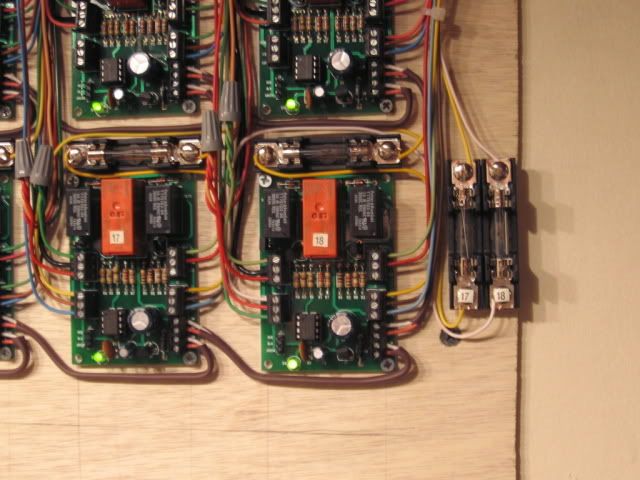
I bought these switches from Ross and had them wire them. I am not saying there is anything wrong with them. I just need to know how to alleviate a situation that is occurring in my switching yard.


See the picture for the point at which the locomotive loses power. It stops dead. It is not a very big dead spot as if I have some momentum I can power through it. However as it will be a switching yard I have to go slow at this point and thus the problem.


I am wondering if I can install a jumper wire or power wire somewhere to fix this. So far everything I have tried has made no difference.


It seems worse in reverse. Reverse is going towards the can of wire nuts.


I realize it can be roller spacing on each locomotive. But is there some way to ensure power all the way through both switches?


photo 1

photo 2

Attachments

Images (2)
  • photo 1
  • photo 2
Last edited by OGR CEO-PUBLISHER
Original Post

Replies sorted oldest to newest

I had this problem with the two pickup rollers on the engine hitting the "dead" spots on the switches. I resolved this two ways:

1) add a short straight piece to increase the dead spot spacing between the two switches.

2) change the pickup roller on the engine from a single roller type to a double roller type.


Problem is that the solution needs to work for all the engines you use, which will have many different roller spacings.


Good Luck: Joe K

When it stalls, try touching the wheels with a wire connected to common or just nudge it sideways a bit. Seems you are on two switches and with the rubber tires maybe lost ground?


If not that, with a pad under the locomotive roll it over gently, exposing exactly where the pick-up rollers are.

Last edited by BobbyD

I like Joe K method od adding a short piece of track. It's probably the easiest to do right now before you get the switch machines hooked up. There are other complicated ways to go about , ex    Borrowing an outside rail and making it Hot via a switch or relay  but it's a pain the butt.  Sometimes it's not always the center rail  and engines with traction tires can be a problem,,, Wiring both outside rail together in a yard  is a good idea.

Originally Posted by Joe K:

I had this problem with the two pickup rollers on the engine hitting the "dead" spots on the switches. I resolved this two ways:

1) add a short straight piece to increase the dead spot spacing between the two switches.

2) change the pickup roller on the engine from a single roller type to a double roller type.


Problem is that the solution needs to work for all the engines you use, which will have many different roller spacings.


Good Luck: Joe K

You lost me on both counts here.  Double roller?  Never heard of that.


How will increasing the dead spot length help?  I thought I am to decrease it.

Originally Posted by Gregg:

I like Joe K method od adding a short piece of track. It's probably the easiest to do right now before you get the switch machines hooked up. There are other complicated ways to go about , ex    Borrowing an outside rail and making it Hot via a switch or relay  but it's a pain the butt.  Sometimes it's not always the center rail  and engines with traction tires can be a problem,,, Wiring both outside rail together in a yard  is a good idea.

I just used two test leads on both sides of the switch.  Alligator clips joining the two outside rails of the main (center) line.  Did not fix the issue. 


It is definitely much worse in reverse.

Originally Posted by Wigville RR:

Make sure all your outside rails have power and run a wire to the center rail between the two switches ,most of the time it is the outside rails the way the switches are, I have lot's switches set up like that with no problems ,


Guy

Outside rails are ground?  I have power where I think I should.  But obviously something is not right as it does stall.

Mark the dead spots where the rollers are on the rail head. 

Use a digital multimeter at these points and verify if the spots are dead. 

If they are both on a frog area then a use a small piece of straight track as suggested above to avoid both rollers aligning up on dead area. If not try to use jumper wires to eliminate the dead spot.

Originally Posted by J Daddy:

Mark the dead spots where the rollers are on the rail head. 

Use a digital multimeter at these points and verify if the spots are dead. 

If they are both on a frog area then a use a small piece of straight track as suggested above to avoid both rollers aligning up on dead area. If not try to use jumper wires to eliminate the dead spot.

It only stops going in reverse.  One direction.  When it stops a slight push on the loco to the side brings back power.  Even with all outside rails tied together via jumpers, both sides of the switches and all outside rails she still stops.


I would prefer to use jumper wires somehow to fix this if possible.  Because if I have to install the straight track it will be a major problem as my drilled holes through the base will all not line up.  Switch machine rods from the bottom (servos) and power drops.


I am not electrically smart enough to know what needs to be connected.  I can locate the rollers when she stops, but from that point how do I determine what to jumper?


I guess I need pictures.  Electricity running through switch machines baffles me which is why I paid Ross to wire them.  LOL

Originally Posted by TurtleLinez:
Originally Posted by Joe K:

I had this problem with the two pickup rollers on the engine hitting the "dead" spots on the switches. I resolved this two ways:

1) add a short straight piece to increase the dead spot spacing between the two switches.

2) change the pickup roller on the engine from a single roller type to a double roller type.


Problem is that the solution needs to work for all the engines you use, which will have many different roller spacings.


Good Luck: Joe K

You lost me on both counts here.  Double roller?  Never heard of that.


How will increasing the dead spot length help?  I thought I am to decrease it.

Does the engine have two pick up rollers per truck? Model number?

(A picture of it on its side at the dead spot would help.)

adding the straight track would increase the distance between the dead spots if it is a center rail issue and should then end the problem.

This diesel unit also stops.  There are dead rail sections in all switches. These Atlas switches have a spot that is  about 1 3/4".  This Weaver E8 has two pick-up rollers that match two dead spots in switches positioned back to back. 


Note the dead rail curved section of track. The other engine pick-up ideally should power the engine at this point when one roller is on this spot.


The dead spots are about 14" apart with these two switches.


The pick-ups on the Weaver E8's are 14" apart. This unit stops on these two switches.


 There is a lot of information on this forum about the Atlas 6924 relay board and power routing to solve this problem.  Do a search for Atlas 6924 relay board and power routing.


You would also note that many new units/locomotives will have (4) pick-up rollers, which limits this problem.


Best wishes with your project

 Mike CT


Last edited by Mike CT

Does the engine have two pick up rollers per truck? Model number?

(A picture of it on its side at the dead spot would help.)

adding the straight track would increase the distance between the dead spots if it is a center rail issue and should then end the problem.

I can snap the picture tomorrow with the loco on its side. 

It only has one pick up roller per truck.

Originally Posted by TurtleLinez:

Only two choices are a relay board or the addition of a straight track?  I assume you cannot just run power wires because a short will be created?  Yes  The relay turns them on and off based on direction? Yes. 


Ross switches using DZ 1000 switch motors and additional DZ 1008A relay has a similar solution.  There should be diagrams with the Ross switches or on the Ross website that detail the power routing wiring.

Best wishes with your project.

 Mike CT


Last edited by Mike CT

The dreaded dead spot.  What you need to do is check the turnout prior to installation.  Turn it over, see if the center rails and the outer rails are wired together before securing the turnout.  Consider how the turnout will function and if no jumper wires are installed add them.  The nice thing about these turnouts is you can use the lack of connectivity in place of a rail gap or insulated connector when creating blocks.  The bad thing is you have to think this through. Sometimes even with the jumpers the space between turnouts and roller distance will place you loco in a situation like the picture above.  The you may have to fudge the track plan a bit to either shorten or lengthen the distance between turnouts.  Before you do anything take a meter and check that current is making it into the dead spot.  If it is then the loco is the issue. If it is not, it is a wiring issue.

Originally Posted by TurtleLinez:
Originally Posted by J Daddy:

Mark the dead spots where the rollers are on the rail head. 

Use a digital multimeter at these points and verify if the spots are dead. 

If they are both on a frog area then a use a small piece of straight track as suggested above to avoid both rollers aligning up on dead area. If not try to use jumper wires to eliminate the dead spot.

It only stops going in reverse.  One direction.  When it stops a slight push on the loco to the side brings back power.  Even with all outside rails tied together via jumpers, both sides of the switches and all outside rails she still stops.


I would prefer to use jumper wires somehow to fix this if possible.  Because if I have to install the straight track it will be a major problem as my drilled holes through the base will all not line up.  Switch machine rods from the bottom (servos) and power drops.


I am not electrically smart enough to know what needs to be connected.  I can locate the rollers when she stops, but from that point how do I determine what to jumper?


I guess I need pictures.  Electricity running through switch machines baffles me which is why I paid Ross to wire them.  LOL

 Even a small piece of Gargraves track between the switches would eliminate the problem. Can't you cut a small piece perhaps around 3 inches long  and stick it between the switches. ??  It's not going to take much, even a shorter piece might work.  I 'd like to see your servo hooked up, I'm also a RC flyer.

Sometimes with the six wheel diesel trucks, the hot pickup will slightly rub the outside rail before the truck begins to turn. Are you seeing any sparking? If not, you probably have the magic dead spot.


When you lay it on its side, peek under it when it stops, check for that situation.


Also, once you get a good photo of it's position, a call to RCS will help.(unless they left for York)


Any other engines do this?

Ah yes the magic dead spot. I remember my Dad telling me an age ole lesson of running every engine I owned across my switch work before I called it done.


I found the magic dead spot appeared between these two curved Ross switches with a set of scale A-B-B-A F3 units. I was lucky and an added jumper solved the issue....


20150124_232624

20150129_212534

Attachments

Images (2)
  • 20150124_232624
  • 20150129_212534
Originally Posted by J Daddy:

Ah yes the magic dead spot. I remember my Dad telling me an age ole lesson of running every engine I owned across my switch work before I called it done.


I found the magic dead spot appeared between these two curved Ross switches with a set of scale A-B-B-A F3 units. I was lucky and an added jumper solved the issue....


What two points did you jumper between?

It looks to me like you need a center rail feeder wire right on the center rail at the switch point end of the switch at the left.   Are you positive that there is center rail power between both switches??  Grab you volt meter , or lighted caboose and check it out.   (just push the caboose through to see it  goes dead and where?)

Originally Posted by Gregg:

It looks to me like you need a center rail feeder wire right on the center rail at the switch point end of the switch at the left.   Are you positive that there is center rail power between both switches??  Grab you volt meter , or lighted caboose and check it out.   (just push the caboose through to see it  goes dead and where?)

Can you take my pic and put a red dot or something where you think I need the feeder?


I can tell you this.  It is only a fraction of an inch where the power drops.  A little bump on the loco and the power comes back.  The switches were slightly warped from Ross.  I thought I screwed them down well but perhaps the engine is rocking just right to break electrical contact?

Here's another thing to consider ..Are both Rollers working??   Place a piece of electrical tape maybe 3 inches long  on any center rail and park the engine with one set of rollers on the tape... The other set of rollers should fire up the engine repeat with other roller.  Do both fire up the engine.    or do a continuity test with rollers at the work bench.

Originally Posted by Gregg:

Here's another thing to consider ..Are both Rollers working??   Place a piece of electrical tape maybe 3 inches long  on any center rail and park the engine with one set of rollers on the tape... The other set of rollers should fire up the engine repeat with other roller.  Do both fire up the engine.    or do a continuity test with rollers at the work bench.

It passes the electrical tape test.  Never hesitates.


I am starting to wonder if the slight unevenness of the Ross switch is the culprit.  The loco rocks a wee bit going through the switches.  Since the span where it loses power is so small I wonder if it is just enough to break ground?  But I did jumper all my outer rails (ground to ground) on all tracks into and out of the two switches.  That made no difference.

Originally Posted by TurtleLinez:
Originally Posted by Gregg:

It looks to me like you need a center rail feeder wire right on the center rail at the switch point end of the switch at the left.   Are you positive that there is center rail power between both switches??  Grab you volt meter , or lighted caboose and check it out.   (just push the caboose through to see it  goes dead and where?)

Can you take my pic and put a red dot or something where you think I need the feeder?


I can tell you this.  It is only a fraction of an inch where the power drops.  A little bump on the loco and the power comes back.  The switches were slightly warped from Ross.  I thought I screwed them down well but perhaps the engine is rocking just right to break electrical contact?

I can't  do the red dot   however  right at the center rail pin (or close on center rail ) where  both  switches join together.

Originally Posted by TurtleLinez:
Originally Posted by Gregg:

Here's another thing to consider ..Are both Rollers working??   Place a piece of electrical tape maybe 3 inches long  on any center rail and park the engine with one set of rollers on the tape... The other set of rollers should fire up the engine repeat with other roller.  Do both fire up the engine.    or do a continuity test with rollers at the work bench.

It passes the electrical tape test.  Never hesitates.


I am starting to wonder if the slight unevenness of the Ross switch is the culprit.  The loco rocks a wee bit going through the switches.  Since the span where it loses power is so small I wonder if it is just enough to break ground?  But I did jumper all my outer rails (ground to ground) on all tracks into and out of the two switches.  That made no difference.

You don't run it over the tape but try to  start the engine up in neutral with one roller at a time parked on the tape.   

Here is another thought.  I didn't realize that this was a Ross switch.  I don't have any experience with Ross, but have plenty experience with Atlas.....and maybe the same issue that Atlas has is also your Ross issue.  What I found with Atlas is that sometimes the black coating does not conduct well. I have found this in other places as well as switches.  I have had to use sand paper, usually about 60 grit to remove the black coating....and I mean remove it completely.  Then follow up with a scotch brite pad to make it smooth.  (Do not use steel wool!)  Then vacuum up the mess.  Then use "Gun Blue" to turn the rail black.  Gun Blue conducts power very well.  Just wipe it after applying so it doesn't get on the rollers.  This has worked for me, again this is on Atlas track.  Maybe the same issue?  And by the way, the Atlas track always showed good continuity when using an ohm meter and volt meter, but when the roller was on the "spot" it would not conduct power to the engine.  Just a thought.  (sometimes it takes a combination of all things suggested to make for smooth running)

Originally Posted by Gregg:
Originally Posted by TurtleLinez:
Originally Posted by Gregg:

It looks to me like you need a center rail feeder wire right on the center rail at the switch point end of the switch at the left.   Are you positive that there is center rail power between both switches??  Grab you volt meter , or lighted caboose and check it out.   (just push the caboose through to see it  goes dead and where?)

Can you take my pic and put a red dot or something where you think I need the feeder?


I can tell you this.  It is only a fraction of an inch where the power drops.  A little bump on the loco and the power comes back.  The switches were slightly warped from Ross.  I thought I screwed them down well but perhaps the engine is rocking just right to break electrical contact?

I can't  do the red dot   however  right at the center rail pin (or close on center rail ) where  both  switches join together.

Not  doubting you, as I do not know diddly here.  But why would you think a feeder right where the switches join?

Originally Posted by TurtleLinez:
Originally Posted by Gregg:
Originally Posted by TurtleLinez:
Originally Posted by Gregg:

It looks to me like you need a center rail feeder wire right on the center rail at the switch point end of the switch at the left.   Are you positive that there is center rail power between both switches??  Grab you volt meter , or lighted caboose and check it out.   (just push the caboose through to see it  goes dead and where?)

Can you take my pic and put a red dot or something where you think I need the feeder?


I can tell you this.  It is only a fraction of an inch where the power drops.  A little bump on the loco and the power comes back.  The switches were slightly warped from Ross.  I thought I screwed them down well but perhaps the engine is rocking just right to break electrical contact?

I can't  do the red dot   however  right at the center rail pin (or close on center rail ) where  both  switches join together.

Not  doubting you, as I do not know diddly here.  But why would you think a feeder right where the switches join?

 Only you can tell us whether there's power on the center rail at that location. If the ross are pre wired there should be. In your pic the engine's left roller  should be picking up power. If this is a new switch try cleaning it, especially the center rail.

Is there power on the center rail at that location?? I can't tell from here.

Add Reply

Post

OGR Publishing, Inc., 1310 Eastside Centre Ct, Suite 6, Mountain Home, AR 72653
800-980-OGRR (6477)
www.ogaugerr.com

×
×
×
×
Link copied to your clipboard.
×
×