Adrian! posted:
cnwdon posted:

Real is always better, thanks, Adrian.  I have to consider things like 10 gauge leads to the track buss for a few blocks to serve some important old trains, so capacitance appears to be my middle name.  If I need to invest in more TIU channels it would be a small cost in the big picture.  Or, what else do I not understand yet?  Would appreciate the “real” answer!

Don

Right so how it "really" works is DCS --- SNIP---

 And if that doesn't scare him, nothing will!

More TIU channels has some drawbacks. One of the biggest flaws in DCS is that it operates serially. So when you add an engine or do a read it does something like this"

for (TIU=1;TIU<5;TIU++){for (channel=1;channel<4;channel++){LOOK FOR TRAIN!}}

Meaning it goes TIU by TIU channel by channel 1-by-1 to add engines, read, or anything else. Nothing is done in parallel. Adding engines takes literally 3-5 min with our 5-TIU setup (compared with 20 seconds on my single TIU layout). If you use the wifi APP things get frustrating after 2 TIUs. It just takes tooooo long to read, find engines, and stuff. Often the app will give a TIU timeout if all the checks don't finish in time.


Thank you.  The time you invest in helping educate us is deeply appreciated.  Assuming I get a scope and learn to use it for this limited application, what I am drawing from your comments is this:

Measure the waveforms at various track locations with a locomotive nearby on that track, for V amplitude and “crispness”, and look at actual loco performance and DCS remote signal ‘strength’.  If the combination suggests it, cut a mainline into two (or more) TIU channels rather than just blocks on one channel, to reduce capacitance per channel.  Am I following your thinking correctly?

Adrian! posted:

More TIU channels has some drawbacks. One of the biggest flaws in DCS is that it operates serially. So when you add an engine or do a read it does something like this"

for (TIU=1;TIU<5;TIU++){for (channel=1;channel<4;channel++){LOOK FOR TRAIN!}}

Meaning it goes TIU by TIU channel by channel 1-by-1 to add engines, read, or anything else. Nothing is done in parallel. Adding engines takes literally 3-5 min with our 5-TIU setup (compared with 20 seconds on my single TIU layout). If you use the wifi APP things get frustrating after 2 TIUs. It just takes tooooo long to read, find engines, and stuff. Often the app will give a TIU timeout if all the checks don't finish in time.


One if the big ones I missed here is the panic reaction time. If you're like me you often run 2 or 3 trains from one remote. So someone screams "your train is about to hit my train" on a block that's serviced by TIU #5. Even if you're super fast and you select the correct engine the remote takes a good 30-40 seconds to poll TIUs #1 to #4 before it will poll #5 and switch to that engine as the active one in the app or on the remote. By then it's already a train wreck.

cnwdon posted:

Thank you.  The time you invest in helping educate us is deeply appreciated.  Assuming I get a scope and learn to use it for this limited application, what I am drawing from your comments is this:

Measure the waveforms at various track locations with a locomotive nearby on that track, for V amplitude and “crispness”, and look at actual loco performance and DCS remote signal ‘strength’.  If the combination suggests it, cut a mainline into two (or more) TIU channels rather than just blocks on one channel, to reduce capacitance per channel.  Am I following your thinking correctly?

Yup that's how we did it basically. There are other small tricks you can do with wiring using sections of twisted and non-twisted wire to cancel capacitance (link for people who might care), but in general we just try to keep everything well distributed among the 20 TIU channels  (5 of them).

Last edited by Adrian!
gunrunnerjohn posted:

Adrian, the big red button.

This is even more complicated!. If you put big red buttons everywhere, the visitors and guests push them. Like 3 times an hour or more. If you put them nowhere then it's a demolition derby but with $1000 models. If you put them in strategically determined locations, then they are always out of reach at the critical moment because in general, you are where the guests are. We've wrestled with this one for 3 years.

I'm working on the RC controlled red button as we speak.

Ah hah!  The practical world always wins.

Our replies crossed.  I get now that adding channels is to be done with discretion, because it has other costs.  I would have them on one TIU in my case, for the longest two mainlines that are in question (2 mains times 2 channels per main, likely), and I’ll keep that one designated as TIU #1 after reading this.  Since I set them up with banana plugs, I can take one “to the bench” and tell it what its number is without much trouble, following the directions for this in Barry’s book.  I expect to have no more than three TIUs when all is completed.

Second: the issue of operating rules and following your train, and now that you mention it, not too high a momentum setting on the locos so panic stop is less needed.  “Superdetailing with sound” (a magazine editor’s apt term), using whistle/horn and bell per the railroad rules, so everyone knows when you start an engine and move it (bell) in a congested place.  And brownie points for violations  which will likely mean, a crushed rubber pedestrian appears under your locomotive, and you bring the brownies for the next operating session.  Fortunately, in my case there won’t often be two trains on one main, so collisions in the absence of accidentally thrown switches are not a big concern.  Smooth trackwork, slow speeds, and managing train length equals few derailments here, also.  

RE: Dividing and using more TIU channels?   Further experimentation has led to “no need”.  This is even after adding a long length of 10 gauge block feed wire for voltage drop reduction to one of the blocks in the long, 2-block main being tested.  Please see string of entries in “Striking signal difference for PS3 vs PS2.....” thread for a lot of trial and test results.

https://ogrforum.ogaugerr.com/...6#136430258707148796

Adrian! posted:
cnwdon posted:

Thank you.  The time you invest in helping educate us is deeply appreciated.  Assuming I get a scope and learn to use it for this limited application, what I am drawing from your comments is this:

Measure the waveforms at various track locations with a locomotive nearby on that track, for V amplitude and “crispness”, and look at actual loco performance and DCS remote signal ‘strength’.  If the combination suggests it, cut a mainline into two (or more) TIU channels rather than just blocks on one channel, to reduce capacitance per channel.  Am I following your thinking correctly?

Yup that's how we did it basically. There are other small tricks you can do with wiring using sections of twisted and non-twisted wire to cancel capacitance (link for people who might care), but in general we just try to keep everything well distributed among the 20 TIU channels  (5 of them).

Can you list some of the small tricks you refer to in your post above, using twisted & non-twisted wire to cancel/lower capacitance.

Thanks,

Bob D

RJR posted:

Adrian, why would twisting wire affect inter-conductor capacitance, since the two conductors remain the same distance from each other?

Twisting the wire isn't for reducing capacitance. It's to balance the line so common mode transients couple to both cables and can be subtracted out at the receiver. It also reduces inductance (and ringing) and provides a constant line impedance so the network remains well matched.

rad400 posted:
Adrian! posted:
cnwdon posted:

Thank you.  The time you invest in helping educate us is deeply appreciated.  Assuming I get a scope and learn to use it for this limited application, what I am drawing from your comments is this:

Measure the waveforms at various track locations with a locomotive nearby on that track, for V amplitude and “crispness”, and look at actual loco performance and DCS remote signal ‘strength’.  If the combination suggests it, cut a mainline into two (or more) TIU channels rather than just blocks on one channel, to reduce capacitance per channel.  Am I following your thinking correctly?

Yup that's how we did it basically. There are other small tricks you can do with wiring using sections of twisted and non-twisted wire to cancel capacitance (link for people who might care), but in general we just try to keep everything well distributed among the 20 TIU channels  (5 of them).

Can you list some of the small tricks you refer to in your post above, using twisted & non-twisted wire to cancel/lower capacitance.

Thanks,

Bob D

We look at the track with the scope and if we see the time constant is low we intentionally untwist a section of wire, or we put a turn or two in shunt with a large resistor to ring it out with shunt inductive peaking. It's works pretty well if the section of track you're trying to peak out isn't too long.


Last edited by Adrian!
RJR posted:

Tanks, Adrian.  That's what I thought.  But your statement, "There are other small tricks you can do with wiring using sections of twisted and non-twisted wire to cancel capacitance" threw me.

Cancelling capacitance is how inductive peaking works. A well placed and well sized JwL cancels a -J/wc. Since a track section has some length and the train can be anywhere on that length you can't cancel it perfectly but if the rise/fall time is really bad you can generally square it up across the section with the right shunt RL in the right place.

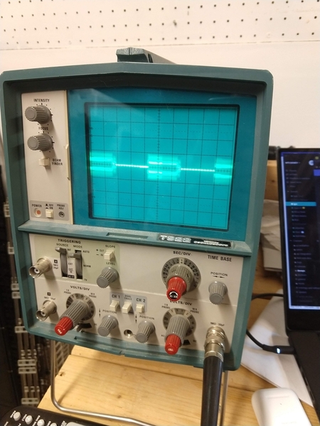
So I got really interested in this thread and occasionally I have a random signal problem with my TIU.  I was curious to measure my 10+ year old Rev. I3a so I broke out my old scope to give this a whirl.

I built the filter circuit Adrian described, and then hooked up the scope and started adjusting it to find the DCS packets.  Since my scope is analog this was more difficult than I thought, mainly because the scope is old and the knobs are fussy.

What really helped was turning on the Protocast feature so the signal was repeatedly sent and I could adjust my trigger. Anyway here’s what I got...

B456EA38-F8E4-40E2-A612-3E86993172EF
Im using a 10x probe so I think the voltage is 4Vp-p.  Is this sufficient, degraded, or what?  All 4 TIU channels measured the same. 

Attachments

Images (1)
  • B456EA38-F8E4-40E2-A612-3E86993172EF
Last edited by rplst8

How are you measuring this?  Are you powering the TIU channel?  Are you using a filter to remove the 60hz?  Are you using a pure sine wave transformer?  I can't really see what you have set on the 'scope, but 2V P-P is WAY too low an amplitude!


I’m measuring using the filter you posted the picture of, connected to the output of the TIU. I meant to say 4Vp-p.  Scope is on 2V/div, time is 1ms.  Your looking at roughly  three “packets” of the DCS signal.

Since recently old threads keep popping up figured it was my turn

Our club is building a new layout and I stumbled across this problem and solution I was wondering if anyone knows if this issue was ever addressed as new TIU's were built? I recently bought a new TIU from a dealer for the new layout and now worried if this was ever fixed for newly manufactured TIU's and if I need to go ahead and something in there so we don't end up with a lack of DCS signal

Thanks in advance

Well that's what I was guessing the answer was going to be. So most likely I would be best off going in and adding the TSB Mod from MTH or the PCB you whipped up before getting it all wired in just to have to remove it. Is there one method that is better than the other?

As far as the members in this particular club we'll just pretend that WTIU doesn't exist. I'll be doing good if I can push the Cab-1 remote and base off to the side and get them to at least use a Cab-1L remote.

Add Reply

Post
The DCS Forum is sponsored by

OGR Publishing, Inc., 1310 Eastside Centre Ct, Suite 6, Mountain Home, AR 72653
800-980-OGRR (6477)
www.ogaugerr.com

×
×
×
×
Link copied to your clipboard.
×
×